Note: Descriptions are shown in the official language in which they were submitted.
~1 -
13~55~
P.C. 7378
COMPRESSION ANASTOMOSIS COUPLING ASSEMBLY
The present invention generally relates to
anastomosis of living tissue and, more particularly, it
relates to an assembly of interlocking coupling members
used for compression anastomosis of tubular structures.
The assembly has an improved locking fea~ure which
prevents inadvertent member dislocation after
installation o a coupled assembly in a body. Also
contemplated by the invention are various coupling
member configurations which will facilitate placement
of the assembly in a patient and enhance in the removal
of a surgical instrument typically used in positioning
the assembly in the patient.
A compression anastomosis coupling assembly of the
type herein disclosed is typically used when a segment
of a colon, or like tubular structure, is to be
resected. After a section of the colon is removed!
leaving opposed, proximal and distal, free ends, the
coupling members are introduced, aligned and brought
into lockîng engagement. The assembly, however, is
equally suitable for use in surgical operations for
connecting tubular structures in other than end to end
orientation, namely 9 the assembly could be used to
achieve either an end to side or a side to side tubal
connection. The coupled members capture and compress
the free ends of the colon together to effect an
anastomosis by holding tissue in compression until
healing occurs. Blood supply to the captured tissue is
restricted. Necrosis takes place in the area of the
colon captured within the assembly without causing
excessive inflammation and trauma. Thereafter, the
coupled assembly detaches from the anastomotic site and
~ $
-2- l 31 ~55~
is e~pelled spontaneously through the rectum. After
assembly expulsion, the colon provides an open
passageway at the anastomotic site substantially as
that which existed before resectioning.
Disclosure of another device used for circular
anastomosis of hollow organs can be found in U.S.
Patent 4,598,712. This device advanced the known art
field by introducing a new technique for compression
anastomosis of hollow organs which, in the majority of
cases, had previously been performed by using
mechanical staplers for connecting tissue edges by
means of metallic staples. Specifically, this device
includes a three member coupling assembly having a rear
locking feature wherein the inner coupling member of
the device includes a conical portion which locks at
the base of the intermediate coupling member locking
the elements of the device. The present compression
anastomosis coupling assembly further advances the art
field by introducing a forward or inner locking feature
in place of the known rear locking feature. The rear
lock, while secure, provides a single locking
arrangement whereas the ~orward lock provides a
multiple fastening arrangement. In the forward locking
configurationl the integrity of the coupled assembly is
further enhanced since forces are equally distributed
around the locking circumference and the locking force
increases as the assembly is subjected to external
forces. In yet another improved locking arrangement,
there is a mechanical locking directly between each of
the three coupling members. An additional feature of
the new assembly which is an improvement over the known
device relates to the enhanced ease in placement of the
assembly in a patient. Typically, a surgical
instrument, having a cutting element for cutting a
member of both the known and the new devices, is
131055~
commonly used with each assembly during implantation.
~owever, the outer element of the known device does not
provide a cutting guide mechanism for guiding the
cutting element during device installation. The new
and improved assembly includes a cutting guide on a
face of one of the coupling members. Additionally,
while the known device provides a cutting ring or
recess on the outer element to help reduce the forces
necessary to achieve cutting, the new device further
reduces the required cutting forces by changing the
configuration of the coupling member through which the
cutting element must pass.
The primary objective of the present invention is
to further advance the art field by providing a compres-
sion anastomotic coupling assembly which is an improve-
ment over existing devices. Accordingly, herein dis-
closed is an implantabl~ device which is designed and
configured for greater ease in installation and which
will eY~hibit a superior in place locking feature during
healing at the site of anastomosis and thereafter be
naturally expelled intact by the patient.
The device of the present invention is a novel
assembly for compression anastomosis of a tubuLar
structure. The assembly includes first, second and
third coupling members, each being biocompatible and
each being generally a hollow open cylinder, with the
first coupling member being dimensioned and configured
to receive therein at least a portion of the second
coupling member and with the second coupling member
being dimensioned and configured to receive therein at
least a portion of the third coupling member. A lock-
ing feature included on the second coupling member is
adapted for locking coaction with complementary means
disposed proximate a first end of the third coupling
--4--
1 3 1 055~3
member. With each coupling member being aligned and
urged into engagement, the third coupling mem~er forces
the second coupling member into locking engagement with
the first coupling member, and the first end of the
third coupling member mechanically locks within the
second coupling member, thereby effecting an assembly
of interlocking coupling members.
In one form of the assembly of the invention, the
coupling members are generally thin wall hollow open
cylinders with the second and third members having open
ends and the first member having one open end and
another end having a surface. The locking feature
might include a land on the second coupling member
coacting with a complementary projection on the third
lS coupling mem~er. Alternatively, the land might be on
the third coupling member and the projection on the
second coupling member. This form of the invention
might also include a recess disposed in the surface and
a means for guiding a cutting instrument adapted for
usage with the assembly during assembly installation.
Also contemplated is a coupling element disposed on the
inner ace of the surface of the first coupling member
for latching engagement with an instrument adapted for
usage during assembly implantation in a patient.
In another orm of ~he assembly of the invention,
the assembly comprises a first coupling member being
generally a thin wall hollow cylinder having ~irst and
second ends with the second end being open and the
first end having a surface with an axial port. The
assembly also includes a second coupling member being
generally a thin wall hollow cylinder having open first
and second ends and including a first portion having
one or more openings disposed in the wall. Addition-
ally, the assembly includes a third coupling member
being generally a thin wall hollow cylinder having open
1 3 1 055~
first and second ends. The first coupling member is
dimensioned and configured to receive therein the first
portion of the second coupling member with the second
coupling member being dimensioned and configured to
receive therein at least a portion of the ~hird
coupling mem~er. A means, disposed on the first
portion of the second coupling member, is adapted for
locking coaction with complementary means disposed
proximate a first end of the third coupling member.
lo With each coupling member being aligned and urged into
engagement, the third coupling member forces the first
portion of the second coupling member into locking
engagement with the first coupling member, with the
first end of the third coupling member mechanically
locking within the first portion of the second coupling
member, thereby effecting an assembly of interlocking
coupling members. As aforesaid with respect to one
form of the in~ention, this form of the invention might
also include like locking and cutting guide features.
Also contemplated within the scope of this form of the
invention is a recess which might bP located on either
the inner or the outer face of the surface. Further-
more, the recess might comprise either one or more
continuous channels which might follow either a spiral
or an angular path. Lastly, the surface of the first
coupling member might include one or more openings
disposed therein forming a spoke-like configuration.
In yet another form of the assembly of the
invention, the assembly includes a direct mechanical
lock between first and third coupling members, locating
second coupling member therebetween, effecting an
assembly locking the three coupling members together as
a unit. Furthermore, a second locking feature,
directly locking the second and third coupling members
to one another, might also be included.
1310558
The various features of novelty which characterize
the invention are pointed out with par~icularity in the
claims annexed to and forming a part of this disclo-
sure. For a better understanding of the invention, its
operating advantages and spPcific results obtained by
its use, reference should be made to the corresponding
drawings and descriptive matter in which there is
illustrated and described typical embodiments of the
invention.
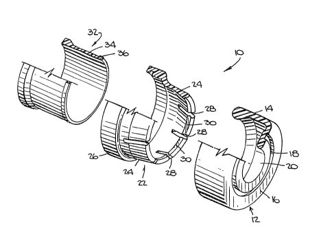
FIG. 1 is an exploded perspective cutaway
representation of a compression anastomosis coupling
assembly, in accordance with the principles of the
present invention, illustrating an embodiment ~f
coupling members prior to interlocking assembly.
FIG, 2 is an enlarged exploded axial cross
sectional view of each coupling member of the assembly
depicted in FIG. 1.
FIG. 2A is a view much like that depicted in
FIG. 2 showing a modified coupling member assembly.
FIG. 3 is an enlarged top plan view of a modified
coupling member similar to the rightmost member shown
in FIG~ 1~
FIG~ ~ is a cross-sectional ~iew taken along line
4-4 of FIG~ 3~
2s FIG. S is an enlarged perspective cu~away view o
another modified coupling member similar to the right-
most member shown in FIG~ 1~
FIGo 6 is an axial cross-section view taken along
line 6-6 of FIG. 5.
FIG~ 7 is a top plan view of yet another modified
coupling member similar to the member depicted in
FIG~ 3~
FIG~ 8 is a schematic sectional representation of
the coupling members, including a surgical instrument
_7- 131055~
used during implantation, being located in ~ree ends of
a sectioned colon but before the members are moved into
locking engagement.
FIG, 9 is a schematic sectional representation
similar to that illustrated in FIG. 8 and showing an
implanted coupled assembly, capturing and compressing
together the free ends of the colon, which will hold
the colonic tissue in place until the anastomosis is
healed.
The description herein presented refers to the
accompanying drawings in which like reference numerals
refer to like parts throughout the several views.
First turning to FIGS. 1 and 2, there is illustrated an
exploded perspective cutaway view and an enlarged
exploded axial cross-sectional view, respectively, of
assembly 10 of the present invention. The assembl~
includes a first coupling member 12 having wall 14,
surface 16, recess 18, and axial port 20; a second
coupling member 22 having first portion 4 and second
portion 26 wi~h portion 24 having at least one opening
28 and land 30; and a third coupling member 32 having
wall 34 and projecting portion 36. Recess 18, in this
embodiment, is located in the outer face of surface 16
of member 12 and recess 18 is a continuous channel.
The inner face of surface 16 is that face being in
juxtaposition with coupling member 22. While land 30
is shown to be located on portion 2~ of coupling member
22 and projection 36 is shown located on coupling
member 32, it should be understood and contemplated to
be within the scope of the invention, that the
locations of the land and projection could be inter-
changed.
Coupling member 12 is illustrated as having an
annular recess 18 and an axial port 20. It should be
.
-~- 1 3 1 055~
understood that other recess configurations are also
contemplated to be within the scope of the invention.
Likewise, that while member 12 has an axial port, it is
also contemplated that surface 16 of member 12 be
continuous, namely, not include an axial opening.
Lastly, although not shown, it is also con~emplated
that means, for example, a snap ring or a plug, could
be included on the inner face of surface 16 to achieve
a latching engagement between coupling member 12 and a
mating ring or socket included on an instrument adapted
for usage during member installation. Other comparable
coupling means could also be employed.
As can best be seen in FIG. 2, the coupling
members are in coaxial alignment for coupling. The
coupling members are dimensioned and configured so that
member 12 is adapted to first recei~e therein portion
24 of member 22 and member 22 is adapted to then
receive therein a portion of member 32. Portion 24 of
member 22 is constructed of a resilient material 50
that during coupling, as member 32 slidingly advances
within member 22, portion 24 is expanded circumferen-
tially until projection 36 reaches land 30, after
which, portion 24 snaps par~ially back to interlock
projection 36 and land 30. Member 32 is now locked
against rearward retreat. Cutaway sections 28 enhance
~he expansion of portion 24 during advancement of
member 32 within member 22, The configuration of the
inner surface of wall 14 of member 12 is such that it
captures expanded portion 24 of member 22 therewithin.
Thus, the three coupling members effect an assembly of
interlocking coupling members after the forcing of
portion 24 into engagement with member 12 and the
locking coaction of projection 36 and land 30
mechanically locking members 22 and 32 at a location
within portion 24.
9- 1 3 1 055~
FIG. 2A depicts a view substantially as ~ha~
depicted in FIG. 2. Coupling member 12 has been
modified to include projecting segment 21. It should
be understood that segment 21 might be a continuous
circular member or it might include a plurality of
downward projections. Segment 21 might latch about
second portion 26 of member 22, passing between members
22 and 32, or about base portion 37 of member 32,
passing through the interior of member 32. Member 32
might mechanically lock within first portion 24 of
member 22 as aforesaid to provide a second locking
feature. Alternatively, member 32 might extend ~hrough
member 22 and fasten to member 12 at any number of
locations along segment 21 by suitable means, for
example, projec~ion 36 might be located in a recess or
a land (both of which are not shown) along segment 21,
to name but two possibilities. Other comparable
mechanical coupling means for directly joining members
1~ and 32 are deemed to be within the scope of the
present invention.
Turning to FIGS. 3 and 4, there is shown an
alternate construction of a member like coupling member
12, here designated as 38. Couplin~ member 38 includes
surface 40, recess 42, axial opening 44, and cutting
guide rib 46. Recess 42 is like recess 18 Pxcept that
recess 42 is located on the inner face of surface 40.
Surface 40 and axial opening 44 are like surface 16 and
axial port 20 shown in FIG. 2. Cutting guide rib 46 on
inner face of surface 40 provides a means ~or guiding a
cutting instrument, such is the type shown in FIG. 8
and identified as 86, for usage with the assembly
during assembly installation. It should be understood
that a cutting gu;de rib could also be provided on the
inner face of surface 16 of coupling member 12 and also
function therein as a guide for a cutting implement.
13105~
It should further be understood that an annular bevel
(not sh~wn) could replace cutting guide rib 46 and
provide a comparable cutting guide function.
Turning now to FIGS. 5 and 6 9 there is shown
another alternate construction of a member somewhat
like coupling members 12 and 38, here designated as 48.
Coupling member 48 includes surface 50, recess 52,
axial opening 54, and cutting guide rib 56. The
primary distinction in this embodiment is that ~he
confi~lration of recess 52 follows a number of angular
paths. Not shown but also contemplated within the
scope of the invention is a recess that follows a
spiral path. The remaining member features are like
those shown in respect to members 12 and 38.
FIG. 7 shows yet another alternate construction of
a member like members 12, 38 and 48l here designated as
58. Coupling member 58 includes surface 60, cutting
ring 62 having openings 64 and spokes 66, and axial
port 68. Coupling member 58 might also include a
cutting guide rib (not shown) much like rib 46, 56.
Throughout the many ~iews a recess has been included in
the first coupling member. The terms recess and
cutting ring could often be used interchangably, that
is, at least when the recess assumes an anntllar shape.
An advantage of a cutting ring having a spoke-like
configuration is that openings 64 form passageways to
allow the escape of gases during member installation.
Additionally, with the removal of material from surface
60, lesser operating forces will be required during
cutting of member 58 as the assembly is placed in a
patient. It should readily be understood that each of
coupling members 12, 38, 48 and 58 are suitable for use
with coupling members 22 and 32.
The forward or inner locking feature herein
provided, namely, the mechanical locking of members 22
-11- 1 31 055~
and 32 engaging at 30, 36, provicles a more secure
locking arrangement than that found wherein members
lock at a rear location. A rear locking feature,
namely, at the base of member 22 where it contacts the
base of member 32, is a single locking arrangement
about the base whereas the inner locking feature
provides a multiple locking arrangement, that is, a
separate lock at each location where land 30 and
projection 36 meet. This multiplicity of locking
feature exists because land 30 is circumferentially
interrupted by slots 28 disposed in wall 24 and each
land and projection meeting provides an independent
locking engagement. The forward locking feature
prevents the innermost member 32 from backing out when
force is applied to the assembly and, since the force
is equally distributed around the locking circumfer-
ence, the integrity of the coupled assembly is enhanced
because the locking force increases as the assembly is
subjected to external iorces. The various recess or
cutting ring configurations of coupling members 38, 48
and 58 provide the advantage of reducing the cutting
forces necessary during member installation to cut
through the face of the coupling member by reducing the
surface area and thickness the cutting edge is cutting
against. The cutting guide ring, suitable for inclu-
sion in any of coupling members 12, 38, 48 and 58,
provides the additional advantage of consistency of
operation by allowing the cutting edge to follow a
specified path.
Turning now to FIG. 8, there is shown a schematic
representation of an uncoupled assembly of coupling
members located in a sectioned colon. While the
assembly is shown in conjunction with colon repair, it
should be understood that use of the assembly is
equally applicable for the repair of other tubular
-12- l 31 055~
structures such as the large and small bowel and the
esophagus to name but a few. Colon 70 having wall
portions 72, 74 and free ends 76, 78, is shown having
an assembly implanting device 80 located therein.
Device 80, in one end of colon 70, supports coupling
member 12 at the end of central portion 82 engaging a
knob portion 84. In the other end of colon 70, device
80 supports coupling members 22, 32 and a cutting blade
86. During assembly installation, ends 76, 78 are
gathered against central portion 82 of device 80, the
three coupling members are urged into contact and
pressed into full locking engagement, cutting blade 86
is advanced to cut the ends 76, 78 and then to cut
member 12 along and through ~he inner face of surface
16 at the location of recess 18, and thereafter device
80 is withdrawn through colon 70 leaving ~he assembly
as shown in FIG. 9. The anastomosis will heal in and
about the region designated 88 and thereafter the
assembly will naturally be expelled intact by the
patient leaving colon 70, at the anastomatic site, with
; an open passageway substantially like that which
existed before resectioning~
~ile in accordance with provisions of the
statutes there is described herein a specific embodi-
ment of the invention, those skilled in the art will
understand that changes may be made in the for~ of the
invention covered by the claims appended hereto withou~
; departing from the scope and spirit thereof, and that
certain features of the invention may sometimes be used
to an advantage without corresponding use of the other
features.