Note: Descriptions are shown in the official language in which they were submitted.
~3~7~3
The present invention relates to an implantable
heart beat sensing system and in particular to a pacer/
cardioverter for detecting arrhythmias requiring pacing
and also ventricular fibrillation.
`
It is well known that the heart can be monitored by
sensing the elect-rical activity thereof. Many processing
schemes-have been devised to determine the condition of the
heart and to determine particularlyjwhether the heart is
beating at an abnormally slow rate (bradycardia), a normal
rate (normal sinus rhythm), an abnormally fast rate
(tachycardia), a generally chaotic fast rate ~ventricular
fibrillation), or has substantially ceased to beat
(asystole).
.
.
'~
. .
.'~', `
..
.
.
r~
The electrical activity of the heart can be sensed
and the resultant signal pre-processed (for example, by
pre-amplificàtion, filtering, etc.), and then digitized in
some fashion. The digitized signal can ~urther be processed
to specifically diagnose the condition of the heart. These
operations can occur in an implantable device. Based upon
the diagnosis, stimulating pulses are applied to the heart
from the implantable device. The stimulating pulses may
consist of pacing pulses, a low level electrical shock
pulse, or a high level electrical shock pulse. The low and
high level shock pulses are called herein "cardioverting
pulses'i which are commonly in the neighborhood of one joule
of energy or more in contrast to pacing pulses which are in
the microjoule energy range.
In some situations, the electrical activity of the
heart during ventricular fibrillation is at a very low
amplitude level. I the implantable device tests whether
the signal obtained from the heart, herein called a "cardiac
signal", exceeds a threshold levél, the device may diagnose
a heart condition as asystole (-no heartbeat) or bradycardia
(slow heartbeat) and issue pacing pulses when, in fact, the
heart is in ventricular fibrillation (VF) because the low
level electrical activity indicative of VF is insufficient
~ ~e ~
to trigger the threshold detection circu:Ltry of the implantable
device. Such pacing pulses could be detected by the sensing
circuitry and further interference with the recognition of the
life-threatening ventricular fibrillation.
It is an object of the present invention -to obviate or
mitigate the above disadvantage by providing a novel implantable
heart sensing system.
According to the present invention there is provided an
lmplantable system including pacing and cardioverting
capabilities for detecting abnormal heart rates by sensing the
electrical activity of the heart and stimulating the heart
accordingly, the system comprising:
means for sensing said electerical activity of the heart and
for carrying a cardiac signal indicative thereof;
time and amplitude determining means for issuing a pacer
signal when the amplitude of sai~ cardiac signal fails to pass a
first predetermined threshold within a predetermined time period;
amplifying and detection means for amplifying said cardiac
signal and producing a heart rate signal when the amplified
cardiac signal exceeds a second predetermined threshold, said
i amplifying and detection means having an automatic gain con-trol
wherein the gain of the amplifying portion increases with time
` based upon said amplitude of said cardiac signal; and,
means for stimulating said heart based upon said pacer
signal and said heart rate signal.
A method of detecting and treating abnormal heart rates
using an implantable device is also provided.
Preferably, the lmplantable cardioverter/pacer utilizes two
channels respectively producing a pacing signal and a heart
rate signal that are applied to a microprocessor. The pacer
channel includes a sense amplifier which has a set gain and
which triggers a one shot in the presence of the ~-wave peak
in the cardiac signal (ECG signal) applied to its input.
The output of the one shot is applied to a pacer/timer which
determines whether an R-wave is present within a
pre-established time interval. When the R-wave is not
detected, that is, when the one shot does not provide a
reset pulse to the timer, the pacer/timér outputs a pacer
signal to the microprocessor.
The rate detect channel obtains the cardiac or ECG
signal in the same fashion as the pacer channel. That
cardiac signal is initially amplified and then variably
amplified utilizing an automatic gain control (AGC). The
AGC will increase the gain of the controlled amplifier based
upon the initial level of the cardiac signal and the time
between detected peaks of the cardiac signal. The output of
the variable gain amplifier is applied to a one shot which
in turn produces heart rate signals to the microprocessor.
The AGC has a time constant that is greater than the pacing
~ 3 ~ 3
escape interval or the time between normal sinus rhythm
R-waves in th~ ECG or cardiac signal.
In order to detect low level VF cardiac signals, the
microprocessor disregards or blanks out the first and
possibly the second pacing signals from the pacer/timer in
order to alIow the gain in the rate detect channel to
increase and approach a maximum value. When the gain in the
rate detect channel is high, a determination can be made
whether low level VF cardiac signals are present at the
input or whether the heart is undergoing asystole or
bradycardia. By ignoring or blanking out the pacing signals
for a one or two second period, the r~te detect channel does
not detect any pacer artifacts and the microprocessor can
apply the appropriate treatment to the heart either by
issuing pacing pulses, if no low level VF cardiac signals
are detected, or by lssuing cardioverting pulses if VF is
detected.
An embod;ment of the presen;t ;;n~ent;on will now be
described by way of example only w;th re~erence to the
accompanying drawings in whi5h:
~ . ~
.. . .
Figure 1 illustrateskno~ncircuitry for providing a
pacing pulse in a prior art device;
. , ~ S --
., .
., . :
,. . ...
~ . .
.
-
. .
1 3 1 ~ 3
Figure 2 illustrates, in block diagram form, a
cardioverter/paceri
Figure 3 illustrates a graph showing the increase in
gain of the rate detect channel versus time;
. .
Figure 4 illustrates a timing diagram showing the
: rate detect channel sensing the artifact of the pacing
pulses applied to the heart;
Figure 5 shows a timing diagram wherein the pacing
signals are blanked out for a period of time in order to
detect low level VF cardiac signals;
Figure 6 shows the prolongation of the heart rate as
an electrocardiogram signal (herein ECG)~
- and,
Figures 7, 8, 9 and 10 show timing diagrams wherein
the-blanking period is utilized only once and for a certain
number of time intervals thereafter, a pacing pulse is
issued if the R-wave is not detected within each such
interval.
.
-- 6 --
.' , _,
. .
.
'.'
~ ~ 3 ~ 3
Figure 1 illustrates in block diagram form a prior
art device for determining whether an R-wave in the ECG or
cardiac signal is present within a predétermined time
interval and issulng a pacing pulse if such R-wave is not
detected within the time interval. The ECG or cardiac
signal is sensed by appropriate means attached to or
proximate the heart of a patient such as a bipolar electrode
.~
lead, patch or combination thereof. The signal is applied
to pace sens~ leads 12 and 14. Herein, the term "cardiac
signal" is synonymous with the ECG signal. However, the
cardiac signal may be an amplif~ied verslon of the ECG
signal. The cardiac signal from leads 12 and 14 is applied
to sense amplifier 16 which is set by variable resister Rl.
The output of amplifier 16 is applied to one shot 18 and
\
~ - 7 -
t
,,
: .
~3~7~ `
when the amplitude of the cardiac signal exceeds a
predetermined threshold, the output goes high and the one
shot f;rés. One shot 18 produces a reset pulse of a
predetermined duration at its output which is applied to the
reset terminal of pacer timer 20. Pacer timer 20 is set to
generate a pace pulse output if a reset pulse is not applied
thereto within a predetermined time interval. This time
interval defines a heartbeat rate level below which pacing
pulses are applied to the heart. The interval can be set as
can the amplification in sense amplifier 16. Generally,
timer 20 times out shortly after the R-R interval during
normal sinus rhythm or a normal heart beat.
In some situations, ventricular fibrillation is
manifested only by fast rate, very low level electrical
activity. If the low level cardiac signals are insufficient
to e~ceed the trigger threshold of sense amplifier 16, the
prior art pacing channel shown in Figure l would result in a
pace pulse being issued by pacer/timer 20 at each
predetermined interval in the absence of a reset pulse from
one shot 18. Accordingly, a control circuit, which may be a
microprocessor, would commonly react to the pace pulse by
issuing pacing stimulating pulses to the heart since the
microprocessor would not be provided with an indication of
the low level ventricular fibrillation cardiac signal.
.' ~ .
~ ~ 8 -
.
"
.' ,,
. .
~ 3 ~ ~ 7 t3 ~ !
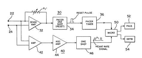
The present device is schematically illustrated in
Figure 2 as a block diagram showing pacer channel 30 and
rate detect channel 40, both receiving the cardiac signal
rom terminals 22 and 24.
Pacer channel 30 is generally similar to the circuit
described above with respect to Figure 1. Sense amplifier
32 has an adjustable sense level based upon the resistance
of resister Rl~. The gain and the sense level of amplifier
32 is programmably set by a series of resistors that are
represented by resistor Rl'. Since amplifier 32 generates
an output when the cardiac signal at leads 22 and 24 exceed
the sense level, the adjustable level is desirable to avoid
certain sensing signals such as the T-wave in the ECG
signal, noise, etc. The input cardiac signal must exceed
the threshold of sense amplifier 32 to trigger pacer one --
shot 34 to produce the reset pulse. A typical range to
trigger sense amplifier 32 is from 0.5 mv to 5.0 mv. Below
that threshold , one shot 34 does not fire or provide an
output and hence pacer timer 36 times out and issues a
pacing pulse to microprocessor control 50.
Since the VF cardiac signal amplitude can vary
dramatically across the sensing leads (for example, a
bipolar lead) which are electrlcally connected to input
leads 22 and 24, the cardiac signal amplitude sometimes
~3~ ~7~
falls below the detectable threshold of pacer channel 30
and hence timer-36 times out and produces a pacing signal to
mlcroprocessor control 50.
Heart rate is one of the detection criteria for
diagnosing ventricular fibrillation. Therefore, it is
necessary to measure cardiac activity below the pace
sensitivity threshold . Rate detect channel 40 in Figure 2
produces a heart rate signal for microprocessor 50
notwithstanding the level of the cardiac input signal
applied to leads 22 and 24.
Rate detect channel 40 includes amplifier 42 for
pre-amplifying the cardiac signal, amp,lifier 44 which
includes an automatic gain control (herein AGC), and one
shot 46 that provides an output indicative of the heart
rate. Interval P, is the R-R interval of the ECG or
cardiac signal detected by rate detect channel 40. Rate
detect channel 40 can also include a comparator or threshold
sensor intermediate amplifier 44 and one shot 46 such that a
signal is only applied to the one shot if it exceeds the
reference or threshold. Alternatively, the one shot can be
set only to trigger when the input signal exceeds a minimum
threshold value.
Generally, the cardiac s1gnal is amplified in
amplifier 42, and then is variably amplified in
.
-- 1 0
. . . .
.. .
.
s3
amplifier 44. The gain in arnplifier 44 is set by the AGC
and is based upQn the initial level o the cardiac signal
applied the~eto as well as the time between the peaks of
that initial signal. When the further amplified cardiac
exceeds a threshold, a signal is applied to one shot 46 and
a pulse is generated therefrom indicating the heartbeat
rate.
Figure 3 shows the gain versus time after sensed
activity curve for the AGC in Figure 2. The AGC has an
inherent time constant required for maximum sensitivity.
The time constant of the AGC is longer than the typical
pacing interval or the R-R interval. The principal reason
for this long time constant is to avoid sensing unwanted
cardiac activity that may create a false indication of
ventricular tachycardia or ventricular fibrillation. Times
tl, t2 and t3 in Figure 3 correspond to the time span
from the reset state to of the AGC. The AGC is reset -
based upon the time of the last sensed peak and the
amplitude of that peak. Therefore, at time to ~ the AGC is
reset due to a normal R-wave in the cardiac signal. Time
tl may correspond to one-half of the R-R interval. Time
t2 may correspond to two or three times the R-R interval
and time t3 may correspond to three or four times the R-R
.
.
.
~ ?~ 1 ~J 7 ~ 3
interval. Of course, if no siynal is sensed until time
t2, the gain of amplifier 44 is approaching a maxirnum.
Figure 4 shows a timing diagram wherein the heart
activity time line, or an exemplary ECG signal, shows sudden
onset of ventricular fibrillation wherein the electrical
signal level of the VF is very low compared to the amplitude
of the R-wave. Pacer one shot 34 issues a reset pulse at
each detected R-wave as shown in Figure 4. Therefore, pacer
timer 36 is reset after interval Pl. However, after that
interval pacer timer 36 times out at the end of interval P2
and issues a pacing signal to microprocessor 50. Timer 36
is then automatically reset, continues to count down and
issues another pacing signal at the end of interval P3. In
prior art devices, microprocessor SO would activate
pacemaker circuit 52 and circuit 52 would issue pacing
pulses to the heart. These pacing pulses stimulate the
heart and the artifacts of the pulses cause rate detect
channel 40 to produce a heart rate signal at the end of
interval P2 as well as lnterval P3. Therefore
microprocessor 50 possibly would not be capable of detecting
the very fast but low level cardiac activity indicative of
some types of VF.
~ ~ ,
- 12 -
.
:`
,
~.
7 f~ 3 `I
Figure 5 illustrates the same heart activity or
cardiac signal, the resulting output of pacer one shot 34
and t~e resulting output of pacer timer 36. ~Iowever, in
Figure 5, the pacing signals are blanked out or ignored by
microprocessor 50 for a two second period (as an example)
such that the AGC increases the gain of amplifier 44 in rate
detect channel 40 and hence heart rate signals are applied
to microprocessor 50 at the end of prolongation interval
P4. In this particular case, the first two pacer signals
were blanked out such that microprocessor 50 could "look
at" the heart rate signal from rate detect channél 40 before
issuing pacing pulses to the heart. Subsequent to interval
P4, microprocessor 50 could determine the appropriate
. treatment to be applied to the heart, i.e., low le~el
cardioverting pulse from defibrillating (or cardioverting)
circuit 54, high level cardioverting pulse, a certain pacing
` - pulse routine, or combination thereof in order to treat
the VF.
` ` Figure 6 shows the ECG signal of a heart that is
subject to bradycardia ~low heartbeat rate). If thR
. blanking period is one or two seconds, the heart beat will
only be prolonged a relatively short period of timè before
pacing pulses are issued by pace circuit 52. After the
blanking period, and in the presence of further pacing
- 13 -
.
"
~ 3 ~
signals applied to microprocessor 50, the microprocessor is
programmed to issue regular stimulating pacing pulses to the
heart based ~pon the pacing signal applied thereto from
pacer timer 36.
The microprocessor can also he programmed to blank
out the pacing signal only once and issue pacing pulses,
through pacer circuit 52, if the heart beat rate remains
below a predetermined level. Figures 7 through 10 show
timing diagrams describing the operation of such a program.
In one embodiment, the pacer channel is used to monitor
heart activity for the pacemaker unction. The rate detect
channel monitors the heart for tachycardia. If the rate on
the pacer channel is above the hysteresis rate or the
predetermined low level heart beat rate, the heart will not
be paced. In Fig. 7, the- time interval between R-wave Ro
and wave Rl in the ECG signal is less than the hysteresis
rate designated by interval AHY5 . InterVa1 B2S-A is the
remainder of the two second blanking-interval for the pacing
signal in this embodiment. In general, if the rate falls
below the hysteresis rate as is shown-in Fig. 7,-after Rl,
the heart will be paced at the bradycardia pacing rate.
However, before a pacing pulse is issued as the rate
decreases below the hysteresis rate level, two seconds must
.
-- 14 --
. .
,,
'' ,''
`:
;~ 3 r11 ~ ~
elapse as shown in the time line. If an R-wave is not
detected on the pacing channel prior to the first hysteresis
tim~out, a two second time out is initiated. If an R-wave
is not detected during the two second timeout
~A' HYS+B2 5 -A) ~ a pace will be issued after the two
second timeout, i.e., at the end of B25-A. If intrinsic
heart activity stays below the bradycardia rate or
hysteresis rate, the heart will be paced at the bradycardia
- pacing rate.
If an R-wave is detected during the two second
interval as shown in Fig. 8 (See R,), one additional
hysteresis interval CHY5 will be timed out. If no R-wave
is detected during this interval the heart will be paced at
the end of the interval if the total time exceeds two
seconds.
~Additional single hysteresis intervals will be timed
`~out ùnless four consecutive R-waves are detected that
indicate a rate greater than the hysteresis rate, i.e., the
R-waves fall within the hysteresis rate interval. If this
happens, the two second interval timeout before pacing will
be reinitiated. Fig. 9 shows wave Rl within the two
second pèriod and wave R2 within hysteresis interval
CHY5 but no other R-wave within the next interval DHYS;
therefore, a pacing pulse is issued at the end of DHYS
.~ ~
-- 15 --
.,
,_
, .
~3~7~33
without recalling the blanking period. Fig. 10 shows waves
R2 and RJ in Intervals CHY5 and D~ys respectively
but a pacing pulse is issued at the end of interval EHYS
because of the absence of an R-wave during that time
interval. In order to reinstate the two second blanking
period, an R-wave would have to be detected during intervals
C~IY5, DHYS, E~lys and FHY5 in order to reset the
microprocessor.`
While only certain preferred features of the
invention have been shown by way of illustration, many
modifications and changes can be made. It is to be
understood that the appended claims are intended to cover
all such modifications and changes as fall within the true
spirit ana scope of the invention.
.
~, .
,.......................... . .
. .
. .
,.,
- 16 -
'.
:
,
., .
. :