Note: Descriptions are shown in the official language in which they were submitted.
1310122
-- 1 --
HAVING VARIABLE REPEAT LENGTH PORTIONS
Background of the Invention
The present invention relates generally to
control systems for phasing a moving web of material
to operating machinery located at a fixed operating
station along the web and, more particularly, a
phasing control system which is adapted to be used in
association with a web having repeat length portions
which are to be phased to the operating machine which
repeat length portions are subject to minor different
length variations.
Web phasing systems have long been employed
for phasing repeating longitudinal portions of a web
having a constant repeat length to operating machinery
along the web. For example, a web phasing system is
used in a cutterline which cuts carton blanks having
printed graphics thereon in order to ensure that the
cut made by the cutter device is always made at
approximately the same position with respect to the
graphics of each repeat length of the web. A phasing
device is necessary to ensure that a longitudinal
misalignment of the web such as caused by slippage in
web conveying rolls, a web splice, or the like, will
not cause each of the repeat length portions occurring
after such slippage, splice, etc. ko be placed out of
registry with the operating station machlnery. If a
significant misregistry of a web repeat length portion
1~1()~22
- 2 -
and an associated operaking machine such as a web
cutter does occur, all ~ucceedlng portions of the web
which are e~fected by such misregistry must usually by
scrapped. Thu , an accurate web phasing device is
essential for any commercial high-speed operation in
which repeat length portions of a web are operated on
at one or more operating stations along the web To
control the phasing of a web with a particular
operating station it is necessary to monitor the
degree of registry of web repeat length portions with
operating station machinery in order to make the
necessary adjustments in the web movement or, in some
cases, in the operating station machinery movement so
as to ensure proper phasing of the web and operating
stations. Such monitoring is generally performed by a
photoelectric scanning device, generally raferred to
in the industry as a "photo eye" unit, which senses
register marks on the web which are associated with
each repeat length portion of the web. In an ideal
control situation, the photo eye unit would be
positioned within the operating station and would
sense a register mark at exactly the time that the
associated operation were being performed on the web.
For example, in the case of a web carton blank cutting
unit, the photo eye would be positioned within the
cutter device and would sense a register mark on the
w~b at exactly the same position that the cutter is
designed to cut the associated web portion. In such a
situation, a cutter position reference signal would
also be generated at the t$me that the cutter was
oriented in the cutting position. The cutter position
reference signal and the web indicia signal would be
compared by associated circuitry or other data
processing means such as a computer to determine the
degres of misregistry of the web with the cutter.
Howev~r, in most ~ituation~, it i~ physically
impos~ibl~ to locate a photo eye unit in exactly the
13107~2
- 3 -
corroct position within an operating station such that
the operating station machinery position reference
signal and the indicia sensing signal associated with
a repeat length portion o~ the web ~eing processed
5 will occur at the same time in response to proper
registry. In order to approximate a situation in
which a web indicia signal will occur at the same
instant as an operating station machine re~erence
signal during proper registry, a register mark sensing
unit i5 often placed at a po~ition at an integer
number of repeat lengths upstream of an associated
operating station, for example, five repeat lengths
away. In such a situation, even though the register
mark associated with a repeat length which is being
operated on by the operating station i8 not sensed at
the same time that a machine reference signal is
generated, a register mark which is then positioned
beneath the photo eye unit will be sensed at that
time, so long as the web repeat length distance
remains constant throughout the web. However, a
problem with such a sen~ing device placement system is
sncountered when web repeat length is subject to
variation such as when the web being processed is a
relatively extensible plastic film web. In such a
situation, even a moderate increase or decrease in the
rep~at length of the web, e.g. 14 inch in a 40 inch
repeat length, will completely disrupt phasing control
o~ the web because each succeeding repeat length error
between the photo eye unit and operating station will
produce an additive misr~gistry ef~ect. Such
misregistry will not be corrected by such a control
system due to the erroneous assumption built into the
control circuitry that the register mark a~sociated
with the sub~ect operating station i~ located exactly
the designed distance, e.g. five, repeat lengths from
the register mark a~60ciated with the ~en~ing device.
To state the problem in a slightly di~erent language,
4 13107~2
prior art phasing techniques phase a web to a point at
an integer number of "ideal" or "design" repeat length
distance~ upstream of an operating station and assume
that this will produce proper phasing at the
operating station as well. This assumption is
incorrect when the actual repeat length distance of
the web portions varies from ~he design repeat length
value. The phasing error resulting from this
incorrect assumption will be approximately equal to
the amount by which the actual repeat length value
varies from the ideal repeat length value multiplied
by the number of repeat length distances that the
photoeye unit is positioned away from the operating
machine. To applicant's knowledge, no one in the
industry appreciated this phasing problem associated
with variable repeat lengths in extensible webs prior
to applicant's identification of the problem.
Prior art phasing techniques are also
inadequate for dealing with another type of problem
2Q encountered with extensible webs~ The repeat length
distance of extensible webs may vary nonuniformly from
repeat length portion to repeat length portion. For
example, one repeat length may be 0.1 inches long, the
next may be 0.2 inches long, the next may be 0.1 inch
2S short. Prior art techniques control phasing by
controlling the position of a repeat length
approaching a sensing unit on the phasing error
measured in the preceding repeat length portion.
Control is achieved by varying the speed of the web in
proportion to the measured error. The control
assumption underlying this technique is that the
phasing error of the next repeat length will be
approximately equal to the phasing error in the sensed
repeat length. This assumption i~ invalid for webs
having repeat lengths which are subject to variation
from repeat length to rspeat length and results in
phasing error in addition to the phasing error
1310722
associated with sensing device displacement from the
operatlng station.
A need thu~ exists for providing a control
system for use in phasing an extensible web to an
operating machine which ad0quately accounts for
variations in repeat length but which does not require
a sensing device to be physically located within an
operating station at the point where an associated
operation is being performed on a web.
Ob~ects of the Invention
It is an object o~ the present invention to
provide a web position monitoring system having a
sensing device portion which i5 located at a position
along the web physically remote from a web operating
station and which generates a reference signal which
corresponds in time to the passage of a register mark
past a fixed reference point within an operating
station.
It is another object of the invention to
provide such a monitoring system which produces a
correct reference signal whether or not the actual
repeat length of an associated web is at variance with
the design repeat length of the web.
It is another object of the invention to
provide such a monitoring system which may be used in
association with other control components to pxovide
proper phasing of a web having repeat length portions
which are sub;ect to minor variations in length.
It is another object of the invention to
provide a control system which generates a control
signal based upon the relative position of each repeat
length portion in the last repeat length distance of
web travel to the operating station.
Summary of the Invention
The present invention achieves the above-
described objectives by the use of a sensing device
positioned at a predetermined distance of web travel
- 6 - 1 31 0722
up~tream of a selected reference point within an
operat~ng station, by use of a web distance measuring
device such as an encoder a~sosiated with a web roll
positioned proximate the register mark sensing device,
and by use of an operating machine cyclical position
monitoring device such as an encoder, The sensing
device register mark detection signal, th~ web travel
signal and the machine position signal are input to a
data processing device such a~ a minicomputer. The
data processing device monitors the distance of web
travel occurring sub eque.nt to the generation o~ each
pulse in a detection signal indicative of the presence
of a register mark at the sensing device. At a point
in time whereat this distance o~ web travel after each
detection pulse is equal to the distance between the
register mark sensing device and the selected
reference point in the operating station, the data
processing device generates a reference pulse which is
provided in a separate rsference signal. Thu6, the
pulses in this reference signal correspond in time
with the passage of a register indicia past the
reference point in the operating station. The
reference pulses in this reference signal are compared
to reference pulses in a machine position reference
signal which occur at the point in time when a
register mark is positioned at the operating station
register point when the web is in proper registry with
the operating station. Variations in the occurrence
between the operating station machine position
reference signal and the indicia ref~rence signal
generated by the data processing means thus accurately
reflect the amount be which the web is out of phase
with the operating station. The register mark
detection signal and web travel signal are also used
to determine the actual repeat length o~ each web
portion. ~his actual repeat length is compared to the
design repeat length to determine a repeat length
1310722
error. The measured phasing error o~ a repeat length
currently in the operating station is added to the
repeat length error of the rspeat length portion which
is immediately upstream of the operating station and
this total error value is used as the basis for
adjusting the speed oE the web during the period that
the next repeat length moves from a position
approximately one repeat length from the operating
station to a registry position in the operating
station. As the sub~ect repeat length moves toward
the operating station, the relative amount of
correction of the total error value that has been
performed is calculated by comparing the web travel
signal to the machine position signal. The control
signal is adjusted based on these comparisons.
Thus, the present invention may comprise an
apparatus for controlling the phasing of repeat length
portions of a moving web to an operating machine at an
operating station along the web wherein the operating
machine has a repeating operating cycle and is
desiyned to perform the same operation on each repeat
length portion of the web-passing through the
operating station and wherein the web is of the type
which is subject to minor variations in the length of
the repeat length portions thereof, comprising: a)
register indicia means associated with each repeat
length portion of the web positioned at a
substantially identical location within each repeat
length portion of the web for sensing by a register
indicia sensing means for indicating the relative
position of an associated repeat length portion: b)
register indicia sensing means positioned at a sensing
station along the web at a preselected distance of web
travel upstream of the operating station for sensing
the passage of said register indicia at said sensing
station and for providing a register indicia sensing
signal ~ndicative thereof; c) web travel monitoring
- 8 - 1310~:2~
means operatively assoaiated with the web for
providing a web travel signal indicative o~ web ~ravel
distance; d) machine reference position sensing means
for sensing the occurrence o~ a cyclically repeating
rQference position of said operating machine and for
providing a machine position raference signal
indicative thereof; e) operating machine movement
sensing means for providing a machine movement signal
indicakive of the relative cyclical machine movement
of said operating machine; f) data processing means
for receiving and proc2ssing said web regisker indicia
sensing signal, said web travel signal, said machine
reference position signal, and said machine movement
signal and for generating a control signal for
controlling the relative rate of movement between said
web and said operating machine based on said
processing of signals for placing each repeat length
portion of the web in proper registry with said
operating machine; wherein said data processing means
comprises web repeat length calculating means for
calculating the length of each repeat length portion
of the web prior to its passage through the operating
station; repeat length error determining means for
comparing qaid calculated length of each repeat length
portion to a predetermined, constant, design repeat
length value for determining the relative repeat
length error occurring in each repeat leng~h portion;
register indicia reference signal generating means for
generating a signal indicative of the passage of a
register indicia past a fixed point associated with
said operating station at a predetermined distance of
web travel downstream of said indicia sensing means;
phasing error determining means for comparing said
register indicia reference signal to said machine
position reference signal for measuring the phasing
error between a web repeat lsngth portion and the
operating machine d~ring each operating machine cycle;
1310722
and error summing means for summing a determlned
phasing error associated wlth one repeat length
portion with the determined repeat length error in th~
next succeeding repeat length portion for determining
an initial total error value for the repeat length
portion immediately upstream of the operation station;
wherein the control signal generated by said data
processing means is based upon said determined total
error value associated with the repeat length portion
immediately upstream of the operating station: wherein
said data processing means monitors and compares at
frequent intervals said web travel signal and sald
machine motion signal during the movement of a web
repeat length portion from a position approximately
one repeat length upstream o~ the operating station to
a position associated with machine registry in said
operating station whereby the relative amount of
correction of said total initial error value
determined for a repeat length portion is calculated
at frequent intervals; and wherein said control signal
is adjusted at frequent intervals based upon said
relative amount of correction of said initial total
error value wherein a relatively gradual web velocity
change is provided in response to said control signal.
The invention may also comprise a method for
controlling the phasing or repeat length portions of a
moving web to an operating machine at an operating
station along the web wherein the operating machine
has a repeating operating cycle and is designed to
perform the same operation at the same relative
position within each repeat length portion of the web
passing through the operating station and wherein the
web is of the type which is subject to minor
variations in the length of the repeat length portions
thereof, comprislng: a) providing register indicia on
the web in association wlth each repeat length: b)
sensing the passage of a web register indicia at a
1310722
-- 10 --
pxedotermined sensing location upstream of the
operating station; c) continuously measuring the
distance of web travel occurring after the sensing of
said register indicia at said sensing station and at
frequent intervals determining the relative distance
of said sensed register indicia from said operating
station based upon said measured distance; d)
monitoring the relative cyclical position o~ said
operating machine; e) comparing said monitor~d
cyclical machine position with said determined
register indicia position at frequent intervals during
the last repeat length distance of web travel before
said register indicia is positioned in a registration
position with ~aid operating machine; f) adjusting the
relative velocity between the movement of said web and
the cyclical movement of the operating machine based
upon said comparison of machine position and register
indicia position at frequent intervals during said
last repeat length distance o~ movement of said
register indicia so as to position said register
indicia at a predetermined fixed reference point in
said operating station at the same time as the
occurrence of a predetermined cyclically repeating
machine operating position.
The invention may also comprise a method for
controlling the phasing or repeat length portions of a
moving web to an operating machine at an operating
station along the web wherein the operating machine
has a cyclically repeating operating cycle and is
designed to perform the ~ame operation at the same
relative position within each repeat length portion of
the web passing through the operating station and
wherein the web is of the type which is subject to
minor variations in the lsngth of the repeat length
portions thereof, comprising: a) providing register
indicia on the web in association with each repeat
length; b) sensing the passage o~ each register
1 0 1 2 2
indlcia at a sensiny 3tation located a predetermined
distance of web travel up~tream from an indicia
registration point in said operating station
associated with a predetermined, cyclically
reoccurring operating machine state and generating a
register indicia sensing signal indicative of the
sensing of register indicia at said sensing station;
c) providing a web travel signal indicative of the
distance of web travel; d) determining the point in
time at which a register indicia is coincident with
said operating station registration point by
determining the point in time at which the web travel
distance occurring after the sensing of an indicia at
said sensing station is equal to said predetermined
web travel distance between said sensing station and
said operating station registration point through the
use of said sensing signal and said web travel signal
and generating a web indicia registration signal
indicative of said coincidence between a web register
indicia and said operating station registration point;
e) continuously monitoring the relative cyclical state
of said operating machine including monitoring the
occurrence of a machine reference state which occurs
at the time a register indicia is located in
coincidence with said operating station re~erence
point during proper registration of said web and said
operating machine; f) determining the web phasing
error distance associated with each repeat length
portion of the web by measuring the distance o~ web
travel occurring between the point in time of
coincidence between a register indicia and the
operating station registration point and the point in
time of the occurrence of said machine reference
state; g~ determining the length of each repeat length
portion by determining the distance of web travel
occurring between a first sensed indicia and the next
sensed indicia using said indicia sensing signal and
1 31 0/2~
- 12 -
~aid web travel signal; h) det~rmining the repeat
length error distance associated with each repeat
length portion of the web by comparing the measured
repeat length distance thereof to a predetermined
design repeat length value and calculating the
difference; i) determining the total web travel
adjustment needed for proper phasing of a repeat
length portion with the operating machine when the
repeat length portion is positioned one repeat length
upstream of the operating station by adding the repeat
length error dis~ance associated with that repeat
length portion to the phasing error distance
associated with the immediately preceding repeat
length portion; j) ad~usting the speed of the web
relative the speed of the operating machine to provide
said web travel adjustment; wherein step j) comprises
monitoring the relative amount of web travel
adjustment that has been made at frequent intervals
during the last xepeat length of web travel upstream
of the operating machine and ad~usting web speed in
relatively small increments during said last repeat
length of web travel to provide an accurate and
relatively constant rate speed adjustment of said web
during said last repeat length of web travel whereby
said web is not ~ubjected to substantial inertial
forces.
Brief Descri~tion of the Drawinq
Fig. 1 i~ a schematic illustration of a
continuous web and various operating stations used in
processing thereof in which the control system of the
present invention is utilized.
Fig. 2 is a top view of the web of Fig. 1.
Fig. 3 is another embodiment of the web of
Fig. 1.
Fig. 4 is a schematic view of~certain
signals generated by the control system of Fig. 1.
Fig~ 5 i8 a schematic illustration o~
1 3 1 0722
- 13 -
another embodiment of a continuou~ web and opsrating
tations used in proce~ing ~hereo~ in which the
control system of the present invention is utilized.
Figs. 6A and 6B ~orm a ~ingle block diagram
illu~tration o~ one method of operation o~ a web
registration control sy~tem.
Datailed Description of the Invention
~ he sensing device ~ignal correction system
of the present invention may be u~ed in a cutterline
10 a illu trated in Fig. 1. The cutterline comprises
a ~erls~ of different areas ~or per~orminy operatlons
on a continuous web of material resulting in th~
cutting of predetermined portions o~ the continuou~
material web 20 to form a plurality o~ individual cut
blanks 112.
The material web 20 moves through the
machine in a longitudinal direction 19~ A~
illustrated in Fig. 2, the web 20 comprises a pair of
parallel lateral edges 21, 22. A repeating pattern of
graphics 23 including register marks 11 designated
individually as A, B, C, D, etc. are printed on th~
web 20 and repeat at predetermined substantial
constant diRtance intervals along the web hereinafter
referred to as the "repeat length" 24. Small
variations in the repeat length may occur du~ to
t~nsion change~, etc. in the moving web. Within each
rQpeat length 24 i8 a dssign cutting location 25, 26,
stc. Tha "design cutting location" refers to the
location o~ the cut which th~ cutter 9~ will cut in
the web i~ the system is operating correctly. The
design cutting location thu~ has a preset r~lationship
with respect to the graphic~ and aæsociated register
indicia 11 in any repeat length of web material. It
will be appreciated that thi~ design cutting location
may vary ~rom the actual cut made in each repeat
lengkh if the web is not prop2rly longitudinally
pha~ed and laterally align~d with the cutter. In the
- 14 - 1 3 1 0 7 ~ ~
embodiment described the shape of the design cut is
rectangular and comprised lateral edges 27, 28
positioned generally parallel the web lateral edges
21, 22 and also comprises a leading edge 29 and a
trailing edge 30 positioned generally perpendicular
the lateral edges of the web. Each repeat length 24
comprises the longitudinal dimension 31 of the design
blank pattern i.e. the length of the pattern and may
also comprises the longitudinal dimension 32 of a
portion of the web 37 positioned between the design
cuts 25, 26 which becomes scrap subsequent to the
cutting of the web~ This scrap portion 37 is
preferably kept to a minimal size and in some
applications may be entirely eliminated. The lateral
dimension or width of the web 33 comprises the lateral
dimension 34 of the blank cutting pattern and the
lateral dimension 35, 36 of the portion of the web 38,
39 positioned outwardly of the design cut which will
also become a portion of the scrap after the web is
cut and which is also preferably kept to a minimal
size.
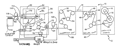
The first station of the cutterline 10 is an
unwind stand 12 at which an unwind roll 14 and a
reserve roll 16 are mounted on a conventional yolk 18.
Each of the rolls 14, 16 comprises a wound continuous
web of material such as paper, plastic film, paper-
film composite, or the like. A typical roll of
material may have a width of 44 inches and a maximum
diameter of 80 inches and may weigh on the order of 2
1/2 tons. The material web 20 is pulled from the
unwind roll 14 until the roll is exhausted. The
trailing edge of the web roll 14 i5 then spliced to
the leading edge of material on the reserve roll 16 at
which point the reserve roll becomes the unwind roll
and another roll is mounted on the yolk 18 in place of
roll 14. Such unwind and splicing operations are
conventional and well-known in the art. The
1 3 1 0722
- 15 -
continuous web 20 is drawn from the unwind roll 14 by
a pair of pinch rolls 42, 4~ located in a decurl unit
40 which may also be used in the web splicing operation.
Subse~uent to passing through the pinch rolls 42, 44 the
web 20 passes over decurl rolls 46, ~8 which take out
some of the curl which sets into a roll of material over
the period in which it is in storage. The decurl rolls
may also be used for lateral alignment of the moving film
web 20. The rolls 46, 48 are mounted on a frame which
may be tilted for side to side to shift the web laterally
as it crosses the rolls to maintain the web in a proper
lateral position. A web edye sensor assembly 4~ is used
to determine the lateral position of an edge portion of
the film web and, based upon this determination, provides
a signal to a hydraulic drive unit 41 which tilts the
frame supporting rollers 46, 48 in response to the
signal to maintain the web 20 in a laterally centered
located in decurl unit 40. Subsequent to passing through
the decurl unit 40 the web may pass into a string inser-
tion unit 50 in which strings may be glued onto the web to
increase web strength. The actual assembly for string
insertion may be of the type illustrated in U.S. Patent
No. 4,496,417. The web passes over a series of rolls 52,
54, 56, 58, 60 in the string insertion unit. ~fter leaving
the string insertion unit 50 the web 20 passes into a
cutter creaser assembly 70 which comprises a plurality of
rolls including idler roll 72 and metering nip rolls 74,
76 driven by variable speed motor 75. Variations in
motor 75 speed may be produced by a mechanical correction
motor and differential assembly (not shown) or by direct
electronic command to motor 75. Both methods of speed
control are well-known and commonly practiced in the
art. After leaving metering nip rolls 74, 76 the web
1 31 0722
- 16 -
pa~ea into a moving curved plate assembly 78 of a
typ~ ~own in the art. The web next passes through
driven cutter feed roll~ 82, 84 prior to enkering a
cutter unlt 90 comprising an upper ~ixed cutter
portion 92 and a lower reciprocating cutter portion 94
which i~ aaused to reciprocate at a constant ~peed by
a cutter dxive motor 96. Fixed knives 98 mounted on
the lower reciprocating cu~ter portion 94 have the
same con~iguration as the design cut 25, 26. Knives
lo 98 have a leadlng edge 95 which corresponds to leading
edge portion 29 o~ a design cut. Subsequent to belng
cut the web passes into driven exit roll nip 116, 118.
Feed rolls 82, 84 and exit roll~ 116, 118 operate
~imultaneously and are rotated and stopped periodi-
cally such that the web portion positioned there-
between is stationary when cut. The portion o~ the
web between rolls 82, 84 and rolls 74, 76 is taken up
by curved plate assembly 78 during the period when
rolls 82, 84 and 116, 118 are stopped to maintain a
relatively constant tension in that web portion.
However, the total distance of web travel between
metering roll~ 74, 76 and cutter blades 98 remains at
a~ effectively con~tant value from one repeat length
cutting operation to the next.
Rolls 82, 84; curved plate assembly 78 and
roll~ 116, 118 are operated by conventional cam timing
devi es associated with a driven shaft portion of cut-
ter motor 96. A cutter encoder 97 is also drlven by a
shaft associated with cutter motor 96 and produces a
signal which is proportional to the angular displace-
ment of the cutter motor sha~t. A cutter sha~t
reference position signal generator 99 also driven by
the cutter motor shaft produce~ a single pulse signal
during each cycle of operation of the cutter which is
indicative of a cyclically repeating cutter po~ition
which in one pre~erred embodiment i8 th~ bottom o~ the
cutting ~troke. SubsQquent to being cut by the cutter
1 31 ~)/2~
- 17 -
unit 90 the web passes over a delivery table 110 where
cut blanks 112, in the shape of design cuts 25, 26,
etc., formed in the cutting operation are caused to
be deposited on the delivery table in stacked
relationship. Operating personnel periodically remove
the stacked blanks 112, placing the blanks on pallets,
etc. for subse~uent transport to other machlnery for
further forming operations such as folding. The
cutter unit 90 and stacking table 110 assembly may be
of a conventional type well-known in the art. For
example, the çutter unit may be model no. Z714
manufactured by Zerand of New Berlin, Wisconsin.
A central control problem solved by the
present invention is the longitudinal phasing o~ a web
20 to a cutter 90 to ensure that the cutter cuts the
web precisely at the design cuts 25, 26 rather than
at some other longitudinal position which is
longitudinally misaligned with the graphic 23 in each
repeat length 24. The apparatus for providing
longitudinal monitoring and control of the web 20 will
now be described.
As shown by Fig. 2, a series of longi-
tudinally ~paced-apart laterally extending reg~ster
marks are repeated at approximately equal repeat
length intervals along the film web 20. The marks are
positioned in a predetermined fixed relationship
relative the repeating graphics and associated design
cuts 25, 26 on the web 20 and are also located in
generally fixed relationship between the lateral edges
21, 22 of the web 20. The marks 11 extend laterally
of the web and are in longitudinal alignment with
respect to the web such that all o~ the marks will be
detected by a single mark detection unit positioned at
a fixed location above the web and de~ining a
longitudinally extending mark detection path 125. In
the embodiment illustrated in Fig. 1, a conventional
photo eye assembly 120 i~ positioned between the mark
1 31 0722
- 18 -
dQtection striny insertion assembly 50 and the cutter
assembly 70 at a location 121 a predetermined known
distance of web travel from the cutter unit so. An
encoder unit 124 which generates a predetermined
number of electronic pulses per revolution of an
associated roller is mounted on roller 72 immediately
downstream o~ photo eye assembly 120. The roller 72
engages the web 20 passing thereover in non-slipping
contact and thus the number of pulses from encoder 124
during any particular time interval is linearly
proportional to the diætance that web 20 has travelled
during that time interval. A data processing unit 100
(which may include a conventional microcomputer or
minicomputer with appropriate control software and
electronics) receives signals from the encoders 97,
124, photo eye 120, cutter position signal generator
99, and also receives a motor speed indicating signal
from metering roll drive motor 75. An input terminal
means such as keyboard 130 is provided to enable
operator input of certain values particular to a web
being run, etc.
Operation of the web indicia reference
signal generating portion of the control system of the
present invention will now be described. Fig. 4
il}ustrates electronic pulse signals provided by web
encoder unit 124, photo eye unit 120, cutter position
indicating signal generator 99, cutter movement
encoder unit 97, and data processing unit 100 at 150,
15~, 154, 155 and 156, respectively. The horizontal
dimension of Fig. 4 represents time. Relatively few
encoder pulses 161, 162, 163, 164, etc. per unit of
length are shown to avoid cluttering the drawing,
however, it is to be understood that in an actual
production unit a high resolution encoder generating
several hundred pulses per inch o~ web travel and per
each 0.01% of machine cyclic movement would be used to
o~tain precise phasing control. ~o further simplify
1 3 1 072~
-- 19 -
th~ sxplanation, an embodiment of the ~ystem in which
the register mark ll-A, 11-B, ll-C, ll-D, etc. in each
repeat length is positioned in coincidence with the
leading edge 29, etc. o~ an as60ciated design cut will
be described with reference to Fig. 3. In the
described embodiment, the position o~ photo ey~ unit
120 is two repeat length~ of web travel from the
leading edge 95 of cutter Xnives 980
The encoder pulse signal 150 ~rom web
encoder 124 and the indicia detection signal 152 from
photo aye unit 120 are both input to the data
processing unit 100. The rectangular shape o~ each
detection signal pulse A', B', C', D', El, F', G',
etc. is indicative of the sensing of a dark region on
the web provided by an associated register mark A, B,
C, D, etc., respectively. The leading edge o~ each
pulse is preferably used as the reference position in
web travel measuring operations described below.
Appropriate software and/or circuitry i~ provided in
processing unit 100 for the functions described below
and the provisions of such software and/or circuitry
i5 within the level o~ skill o~ a person with ordinary
skill in the art.
Processing unit 100 measure~ the distance of
web travel occurring after each pulse A', B', C', D',
etc. in the indicia detection signal 152 by counting
the web encoder pulse~ occurring after each Or ~e
pulses A', B', C', D', etc. This encoder pulse
counting procedure continue~ until a number of encoder
pulses i~ reached that is the equivalent of the
distance between the photo eye unit sensing position
121 and a predetermined longitudinal position 170
within the cutter 90 which in the illustrated
embodiment is opposite the leading edge portion 95 of
the cutter blades 98. As previously mentioned, photo
eye position 121 in the described embodiment is chosen
such that the distance oP web travel between position
1 3 1 0/2~
- 20 -
121 and 170 is two ideal repeat lengths 24. However,
any distance which positions unit 120 reasonably close
to cutter assembly 70 may be used. The processing
unit 100, after counting a number of encoder pulses
equal to the web distance between 121 and 170 (two
ideal repeat lengths), generates a pulse in reference
signal 15~. In the illustrated embodiment, reference
pulses a, b, c, d, e, f, g/ etc. in indi¢ia reference
signal 156 correspond to detection signal pulses A',
B', C', D', E', F', G', etc., respectively. Since
photo eye sensor unit 1~4 is positioned two ideal
repeat lengths of web travel upstream of cutter
station 170, reference signal pulses a, b, c, d, etc.
occur at the same time that the marks A, B, C, D, etc.
which produced detection signal pulses A', B', C', D',
etc. are located at station 170, i.e. when register
indicia A associated with design cut unit 25 is sensed
by unit 120 it produces detection pulse A' and, after
the web has travelled two ideal repeat lengths such
that mark A is positionëd at 170, a pulse "a" is
produced by processing unit 100. In the embodiment
illustrated, the actual repeat length between adjacent
marks AB, BC, EF and FG are each equal to the ideal
repeat length 24 but the repeat length between marks
CD and DE are 20% longer than the ideal repeat length.
Such a large variation in repeat length is unlikely in
an actual operating system but is shown here to
facilitate the description of the invention. A cutter
reference position indicating signal 154, which is
preferably produced by an en~oder associated with a
rotating motor shaft of the cutter unit, is provided
which occurs at the time the cutter begins its cut.
Thi~ machine position thus corresponds to points in
time when the leading edge 29 o~ each design cut 25,
26 etc. would be positioned at station 170 for
properly phased cutting. The machine reference pulse
signals which are output when the cutter is at the
~31()-~22
21
bottom of a cut are represented at a', b', c', d', e',
~', g', etc. These pUlSS coincide in time with
reference pulses, a, b, c, d, etc , respectively, when
the wab is properly phased to khe cutker. As shown by
Fig. 4, machine position signal pulses d', e', f' and
g' are out of phase with indicia reference pulses d,
e, f because of the repeat length error in web
portions DE and EF. The amount of this phasing error
is determined by processing unit 100 by counting the
web encoder pulses occurring between associated pairs
of pulses dd', ee', ff'.
In the example illustrated in Fig. 4, the
control portion o~ the system is not in operatiny and
thus a control signal to correct this measured phasing
error has not been produced. The method of operation
of the phasing and repeat length error control system
of the pre~ent invention is shown in Figs. 6A and 6B.
The repeat length error in each repeat length portion
is determined by counting the number of web encoder
pulseg occurring between the detection of reference
indicia positioned at the beginning and end of each
repeat length, e.g. the repeat length distance of web
portion BC is determined by counting the number of
encoder pulses occurring between indicia detection
signal pulses b' and c'. These measured repeat length
value~ are then compared to the design repeat length
value and a repeat length error value is determined.
The repeat length error value will be given a positive
or negative value depending upon whether the actual
repeat length value is more or less than the design
repeat length value and depending upon the sign
convention used in the control software. The xepeat
length error value for each repeat length portion is
then stored in computer memory.
Even when the control system is operating,
there will be small phasing errors occurring between
some o~ the repeat lengths and the operating machine
1 3 1 U-/2~
~ 22 -
du~ to control inaccuracies caused by control linkage
variables, control lay times, etc., which may not be
entirely eliminated from the system. A phasing error
for each repeat length portion of the web is measured
by counting the number o~ web encoder pulses occurring
between an associated indicia re~erence signal 156
pulse, e,g. c, and a machine reference posikion signal
154 pulse, e.g. c'. This phasing error value will be
assigned a positive or negative value depending upon
whether the indicia reference signal pulse occurred
before or after the machine reference position pulse,
and depending upon the sign convention used in repeat
length error determinations.
A total error value for a sub;ect repeat
length which is positioned approximately one repeat
length of web travel distance upstream of a registry
position with the operating station is determined by
adding the repeat length error of the subject repeat
length to the phasing error of the repeat length
portion immediately preceding the sub~ect repeat
length. This total error value i8 calculated
immediately after the phasing error of the immediately
preceding rep~at length portion is measured. Thus,
the total error value for a subject repeat length
portion is representative of the distance that a
sub~ect repeat length portion is out of phase with the
operating machine when the subject repeat length
portion i~ positioned approximately one repeat length
away from the operating machine. Based upon the total
3~ error value determined for the subject repeat length,
and based upon the actual position of the subject
repeat length with respect to a registration position
in the operating station, a control signal is
generated to vary the web velocity so that the subject
repeat length will be placed in proper registry with
the operating machine when the ~ub;ect repeat length
is at the reference position within the operatiny
- 23 1 ~ 1 0 7 22
station. Control algorithms for maklng ~uch velocity
ad~u~tments are known in the art and may comprise, for
example, a proportional, integral, di~erential (PID)
control algorithm or other algorithms. The PID
algorithm, which is presently preferred, varies
velocity of the web throughout the entire repeat
length distance of web travel occurring between the
time that the control signal for a subject repeat
length portion i~ generated and the time the 8ubj ect
repeat length portion i5 registered with the operating
machin~. Such a gradual veloc~ty ad~ustment prevents
the web from being sub~ect to undue inertial ~orces
which may have a tendency to distort the web,
especially if an exten6ible plastic film web or the
like is being used.
If all control linkage~ and machine
responses were perfect, no further control of the web
would be needed. However, due to inaccuracies
inherent in any control system, the above-described
control function by itsel~ would not provide precise
registration between the web répeat length portions
and the operating machine. Thus, the control sy~tem
is provided with a fine ad~ustment feature to further
control the phasing operation. Thi8 ~ine ad~ustment
feature involves comparison of the web encoder signal
150 to the machine encoder ~ignal 155 to determine the
rslative amount of corrsction that has been
a~complished by the coarse control signal ad~ustment.
These encoder signal comparisons are made at frequent
intervals, e.g. after every ~ inch of web travel or
more fraquently depending upon the speed of the
computer and resolution of the encoders. After each
comparlson of encoder signals, the relative amount o~
total error value correction that has been
accomplished is determined. The control ~ignal i8
thereafter further adju ted depending upon wh~ther the
amount of total error value that has been corrected i~
1310722
- 24 ~
above or below or exactly at the point wh~re it should
be in relationship to the total distance of web travel
that has occurred since the initiation o~ control for
the subject repeat length. Such ~requenk updating of
the control signal thus provides a much more accurate
phasing control than could be accomplished by the
coarse mode operation by itself.
It will of course be appreciated that,
instead of controlling the web velocity wlth respect
to a constant operating machine movement rate, the
operatiny machine movement rate could be controlled
with respect to the web velocity to accomplish the
same result. Due to the relatively great inertia
associated with the operating machine, it is generally
easier to control the web velocity. However, in
situations such as described below with respect to
Fig. 5 in which the machine inertia i relatively
small, it may be preferable to control operating
machine speed with respect to web movement.
A web having a configuration in which each
register mark 11 is positioned in spaced relationship
~rom the web portion 29 that is to be registered with
a particular reference point 170 in an operating
station 70 is illustrated in Fig. 2. In such a
situation, a reference signal indicative of the
passage of web psrtion 29 at a reference polnt 170 is
generated by counting web encoder pulses after each
indicia sensing pulse up t~ a total distance value
equal to the distance between sensing station position
121 and operating station reference position 170 plus
the distance between the portion of the web 29 to be
registered and the associated register indicia 11
wherein the distance between 11 and 20 is treated as
having a positive value if 29 is upstream of 11 and is
treated as having a negative value i~, as in the
illustrated embodiment, web reference portion 29 is
positioned downstxeam of register indicia 11.
~ 3 1 ()722
- 25 -
Another embodiment o~ the invention i8
illustrated in Fig. 5 in which a web 200 mounted
between a driven unwind roll 202 and a driven wind up
roll 204 passes through an operating station 220 at
which material is sprayed onto a selected portion o~
each repeat length of the pa~sing web. The web 200
may have the same configuration as web 20 illustrated
in Fig. 2 and is moved at a relatively constant
velocity between roll 202 and 204. Operating stakion
reference position 222 is selected as the posltion at
which a spray nozzle is positioned which sprays a
small area web portion located at 11 when the web is
properly phased.
An indicia sensing unit 206 is posltioned at
207 at a known distance x which in one embodiment is
five ideal repeat lengths of web travel upstream of
operating station reference positien 222 and generates
a reference pulse each time a web indicia ll is
sensed. An operating station pumping unit 224
periodically discharges spray at reference position
222 at a normally constant rate which is dependent in
the speed of operation of drive motor 226. Motor 226
provides a spray discharge reference signal to a
computer 240 which also receives reference signals
from web indicia sensing unit 206, web encoder 208,
and a spzed signal from driven rolls 202, 204.
Computer 240 generates a web indicia re~erence signal
having pulse~ produced after each detection pulse from
sensing unit 206 occurring after counted encoder
pulses from encoder 210 indicate that a distance of
web travel aqual to x has occurred. This reference
signal i8 compared to the signal from 226 ~or
determining the amount of phasing error in the system.
Repeat length error i8 determined in the same manner
as described above and a total error value is computed
by adding tha phasing error to the repeat length error
associated with ths incoming repeat length. In ono
1 3 1 0722
- 26 -
control mode, the computer 240 produces a control
signal to temporarily vary the speed of roll~ 202, 204
to correct any detected total error value by varying
web speed. In another control mode, computer 240
produces a contrsl signal to temporarily vary the
frequency of operation o~ pumping unik 224 by varying
the speed of motor 226 to phase the operating station
to the web 200.
It is contemplated that the inventive
concepts herein described may be variously otherwi~se
embodied and it is intended that the appended claims
be construed to include alternative embodiments of the
invention except insofar as limited by the prior art.