Language selection

Search

Patent 1310870 Summary

Third-party information liability

Some of the information on this Web page has been provided by external sources. The Government of Canada is not responsible for the accuracy, reliability or currency of the information supplied by external sources. Users wishing to rely upon this information should consult directly with the source of the information. Content provided by external sources is not subject to official languages, privacy and accessibility requirements.

Claims and Abstract availability

Any discrepancies in the text and image of the Claims and Abstract are due to differing posting times. Text of the Claims and Abstract are posted:

  • At the time the application is open to public inspection;
  • At the time of issue of the patent (grant).
(12) Patent: (11) CA 1310870
(21) Application Number: 583215
(54) English Title: APPARATUS FOR HYPODERMIC INJECTION OF LIQUIDS
(54) French Title: APPAREIL D'INJECTION HYPODERMIQUE DE LIQUIDES
Status: Deemed expired
Bibliographic Data
(52) Canadian Patent Classification (CPC):
  • 128/65
(51) International Patent Classification (IPC):
  • A61M 5/30 (2006.01)
  • A61M 5/20 (2006.01)
(72) Inventors :
  • NEWMAN, JACK (Australia)
  • MONROE, JAMES A. (Australia)
(73) Owners :
  • NEWMAN, JACK (Not Available)
  • MONROE, JAMES A. (Not Available)
  • SY-QUEST INTERNATIONAL LIMITED (Australia)
(71) Applicants :
(74) Agent: GOWLING WLG (CANADA) LLP
(74) Associate agent:
(45) Issued: 1992-12-01
(22) Filed Date: 1988-11-16
Availability of licence: N/A
(25) Language of filing: English

Patent Cooperation Treaty (PCT): No

(30) Application Priority Data:
Application No. Country/Territory Date
PI5441 Australia 1987-11-16

Abstracts

English Abstract


- 1 -

ABSTRACT
A device to introduce a liquid into the hypoderma, the device
includes a reservoir which receives a gas under pressure the gas is
delivered via a valve to an interacting piston and cylinder. When the gas
is delivered to the piston the piston moves to eject a liquid from a
capsule mounted within the device. The liquid contained in the capsule is
then ejected through a nozzle located against the skin of the user.


Claims

Note: Claims are shown in the official language in which they were submitted.


The embodiments of the invention in which an exclusive property or
privilege is claimed are defined as follows:
1. A device for introducing a liquid into a patient, including:
a capsule for containing the liquid, the capsule including a
hollow body with a nozzle end through which the liquid exits from within
the capsule, and a capsule piston movably mounted within the body and
operable to push the liquid out through said nozzle end;
a body providing a reservoir for receiving a quantity of gas
under pressure from a gas source;
an interacting actuator piston and cylinder assembly, within
the body, providing a variable volume space behind the actuator piston;
a neck, having a closed end, extending from said reservoir to
said space behind the actuator piston;
means operable by a user to open said closed end to permit
said quantity of gas to pass from said reservoir to said space behind the
actuator piston to cause movement of said actuator piston within said
cylinder;
a piston rod extending from said actuator piston towards an
anterior end of the body and engageable with the said capsule piston to
cause movement thereof upon said quantity of gas under pressure being
delivered to said space behind the actuator piston;
a capsule mounting means, at the anterior end of the body, to
connect the capsule to the body while allowing the capsule to be axially
moveable along the anterior end so that the distance between the capsule
piston and a front end of the piston rod can be varied so that the amount
of penetration of the piston rod into the capsule, upon movement of the
actuator piston, may be adjusted to vary the amount of liquid expelled
from the capsule.
2. The device of claim 1 wherein said mounting means includes a
threaded recess at the anterior end of the body, and external threads on
the capsule that are received within said recess, so that rotation of the
capsule axially moves the capsule along the anterior end of the body to
adjust the position of he capsule.
3. The device of claim 2 wherein the mounting means further
comprises detent means for engaging the capsule.
4. A device for introducing a liquid into a patient, including:
a capsule for containing the liquid, the capsule includes a
hollow body with a nozzle end through which the liquid exits from the
capsule, and a capsule piston movably mounted within the body and


operable to push the liquid out through said nozzle end;
a body providing a reservoir for receiving a quantity of gas
under pressure;
an interacting actuator piston and cylinder assembly, within
the body, providing a variable volume space behind the actuator piston;
a frangible neck extending from said reservoir into said space
behind the actuator piston;
means operable by a user to break said frangible neck to
permit sad gas to pass from said reservoir to said space behind the
actuator piston to cause movement of said actuator piston within said
cylinder;
a piston rod extending from said actuator piston towards an
anterior end of the body and engageable with the said capsule piston to
cause movement thereof upon said quantity of gas under pressure being
delivered to said space behind the actuator piston; and
a capsule mounting means, at the anterior end of the body, to
connect the capsule to the body while allowing the capsule to be axially
moveable along the anterior end so that the distance between the capsule
piston and a front end of the piston rod can be varied so that the amount
of penetration of the piston rod into the capsule, upon movement of the
actuator piston, may be adjusted to vary the amount of liquid expelled
from the capsule.
5. The device of claim 4 wherein said neck includes a weak
section, said neck being fracturable and wherein said device further
includes trigger means operable by a user to fracture sand neck.
6. The device of claim 4 wherein said cylinder and mounting means
are integrally formed, said mounting means is internally threaded at the
anterior end of the body, and wherein external threads on the capsule are
received within said recess so that notation of the capsule axially moves
the capsule along the anterior end of the body to adjust the position of
the capsule.
7. The device of claim 6 wherein said mounting means includes
detent means for engaging the capsule.
8. The device of claim 4, wherein the means openable by a user to
break said frangible neck further comprises a plunger which extends
radially through the body adjacent the frangible neck.
9. The device of claim 8 further comprising a ring rotatably
mounted on the body, the ring supporting an arm which is positionable
over the plunder for facilitating activation of the plunger.

Description

Note: Descriptions are shown in the official language in which they were submitted.


~3~8~


This invention relates to gas operated apparatus to introduce liquid
into the hypoderma. Such devices have use in the administration of for
example local anaesthetlc and insulin and the like.
For many years it was the practlce to deposlt medicaments into the
hypoderma by the use of a device including a tubular needle connected to a
reservoir of medlcanlent lncorporatlng a piston. The needle was inserted
through the epidermls into the hypoderma and the medicament was discharged
by moving the piston along the reservoir. Such devices had several
problems. Firstly the penetration of the needle was a possible cause for
infection and there was the patient resistance to the dlscomfort associated
with the insertion of the needle.
Gas operated devlces were devlsed as an alterndtlve to needle
devlces. In the gas operated devlce llquld medlcament was discharged from
a reservoir through a port as a spray by a plston moved along the reservoir
by sub~ecting it to a force created by the sudden release of gas. Thls
device has the obvlous advantage that there was no skin penetratlon and
hence no dlscomfort and no possibillty of infection.
The common forms of gas devlce comprised a holder to whlch was
coupled to a container of medicament in a manner alignlng lt wlth the
plston to be gas operated and whlch provided means to hold a gas filled
capsule ln the holder. By puncturlng the capsule the gas was released lnto
: a cyllnder and the piston thereln was drlven lnto the contalner to
dlscharge the medlcament through a port ~n the contalner.
; Such an arrangement has several dlsadvantages. For example theholder as provlded was a large member and was complex havlng to provlde
securement means for the medlcament container and the gas capsule. It had
to provlde a plston mountlng arrangement and means to releasably hold th~
gas capsule securely ln a gas tlght manner and puncture the gas capsule.
In short the devlce was large and complex and correspondlngly expenslve.
DG:0155W

8 ~ ~
- 3 -


Disclosed in PCT ~pplication US 86/02718 (publi~hed June 18, 1987 under
PCT publication no. W087/03494) i3 a device with~n which a co~ventional syringe
is mounted. Prior to mounting, the n~edle i~ r~ov~d and the d~vice employs gas
under pressure to cause the piston in the d~vice to mcve ts ~pray from the
syringe body a stream of medication directed at tha ~kin of the patient. This
palticular device has the disadvantage that it is gen,~rally oo~plex to use and
therefore t~me consuming. Firstly, the s~ringe i~ provided wi~l a needle and a
liquid mRdication drawn into the syringe. The needle is then remcved and the sy-
ringe mounted within the device. The d~vice i~ then applie~ to the ~in and operator.
~t ls the object of the present ~nvent~on to oYercomQ or
substantially ameliorate the above disadvantages.
There is disclosed herein a device to introduce a liquld ~nto a
patient sald liquld being contained ln a capsule wh~ch lncludes a hollow
body with a nozzle end through which the liquid exits from within the
capsule and a capsule piston movably mounted ~ithln the body and operable
to push the liquid out through said nozzle end~ sald dev~ce comprising:
a body providing a reservoir to receive a gas under pressure;
an interactlng actuator piston and cyllnder pro~iding a variable
volume space w~th sa~ cyl~nder be~ng f~xed to said body;
duct means extending from said reservoir to sald space;
operator manipulable valve means closing said duct and operable
by a user to open satd duct to permit gas to pass from said reservoir to
sald space to cause movement of sald actuator plston withln said cylinder;
a capsule mounting to rece~ve a capsule; and
a pistqn rod extend~ng from sald actuator piston and extending
there~rom towards sald mountlng and engageable wlth the capsule piston to
cause movement thereof upon gas under pressure being dellvered to said
space.
The present ~nvention in lts preferred form has beQn dev~sed to
DG:0155W

~ 3 ~

overcome the above problems by providlng a simple unitary apparatus which
is provided complete with medicament and pressurlsed gas supply. A single
use renders it unsuitable for further use and lt must be thrown away. rhe
design and the materlal of manufacture of the device proposed by the
present invention makes it economlcally practlcal to throw the devlce away
after a slngle usage.
To cater for the varylng amounts of a medlcament a user may require
the present device ln lts preferred form to be adjustable so that a
predetermlned amount of ~he med~cament can be d~scharged. Thls will mean
that for some users there will be an amount of medlcament thrown away at
each treatment. As will be understood the cost of a medlcament such as
insulln for a diabetlc person is qulte small compared to the convenience
of having a dosage adjustable lnexpenslve devlce that ls convenient to
carry and store is economical to purchase and allows the admlnlstratlon of
the ~nsulin ~n a qu~ck s~mple and convenient manner. For the above reason
lt is proposed to provide a reservolr for the medlcament whlch will cater
;~ for a range of dosages most likely to be needed and thereby allow the user
to select the amount th~t ls requlred to be admlnlstered.
A presently preferred embodlmen~ of the lnvention wlll now be
descrlbed wlth reference to the accompanying drawlng. It ls presently
intended that the dev~ce w~ll be made substantially completely fro~ clear
polycarbonate ln an in~ectlon mouldlng process.
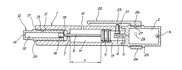
As lllustrated the devlce comprises a body 1 wlth a gas reservoir 2
at one end having a valve 3 of known type whereby gas can be lntroduce~
lnto the reservolr 2 of a fln~shed product. At the fore end of the
reservolr there ls a tubular neck 4 wlth a weak ~one lndlcated 5 where the
neck jolns the reservolr. As wlll be understood lf the neck ls broken off
.-r ~ the reservoir the gas there~n wlll escape. The selected ~ater~al of
manufacture allows the nQck to be readlly broken oPf.
DG:0155~

- ~3~ ~7~
- 5 -
The neck 4 extends lnto a tubular bore 6 in the body l whlch lncludes
an annular shoulder 7. The shoulder 7 serves as a piston travel stop as
will be descrlbed and a guide for a piston rod 8 hav~ng a plston head 9
sealingly slidably mounted ~n the bore 6. There is a gas escape vent 10 in
the wall of the body 1 in communcation wlth the bore 6. The fore end of
the bore 6 ls threaded at 11.
A llquld medicament capsule 12 is provided as a fitment for the
devtce. The capsule is externally threaded at 13 enabling ~t to be screwed
lnto the bore threads 11. The capsu~e has a port 14 at its fore end and
the port 14 ls sealed by a seal that wlll yleld when pressure is applied to
llquid medicament housed in the bore 15 of the capsule 12. Pressure ls
applied to the medlcament by a plston 16 slldably housed in the bore 15.
The exter~or of the capsule 12 is marked ln any sultab~e manner to
indicate fractions of the capacity of the bore 15. For example there may
be external marklngs on the capsule to dlv~de the bore length into flve
sectlons each of Y mls. By threading the capsule 12 into the body the
marklngs on the capsule wlll pass by a datum mark on the body for example
the end face 17 of the body 1 could be such a mark. Detent means ls
preferably provlded whereby the detent ls releasably engaged each tlme a
graduation on the capsule~l2 is allgned with the datum mark. In thls way
the capsule can be releasably locked ln a des~red positlon.
By axially movlng the capsule 12 (as a result of rotatlng lt) the
posltlon of the capsule 12 relative to the end 18 of the plston rod
changes. When the eapsule is fully ln the maxlmum amount of medlcament
~ 25 will be dlspensed. By threadlng the capsule 12 out the amount of
- medlcament dispensed can be reduced.
It wlll be noted that as lllustrated the plston 9 ~s ln lts zero
posltlon agalnst the shoulder 19. The stroke of the plston 9 ls llmlted to
the dlstance X and therefore when the capsule ls threaded fully lnto the
~G:0155W

~3~7~

- 6 -
body so the shoulder 20 engages the end of the body the piston 16 witl be
adjacent the end 18 of the piston rod. The maximum stroke of ~he piston 16
is slightly greater than X. It follows that when the piston 9 moves the
distance X the piston 16 will move the same distance and substantially the
whole of the med~cament in the capsule 12 wlll be ejected. If the capsule
is moved out of the body 1 the piston rod 18 will be spaced from the
piston 16 and although the piston 9 will move X the piston 16 will move
less than X.
In order to release the gas ~n the capsule 2 there ~s a nec~ breaker
in the form of a plunger 21. Pressure ls applied to the plung~r 21 by a
flexible arm 22 through a lu~ 23 thereon. The arm 22 has a ring end 24
rotatably mounted on the body part 2 between shoulders 25. There is a
detent 26 on the ring 24 shown engaged in a depression 27 ~n the body part
2 to align the lug 23 with the plunger 21. In the inoperative position the
15 rtng 24 would be rotated until the detent 26 angages in the recess 28 ln
the body part 2.
In an operatlonal sequence a capsule 12 would be fitted to the
devlce and the amount of medlcament to be dlspensed would be chosen by the
degree to which the capsule 12 ls threaded ~nto the body 1. The lug 23
would be placed over~the plunger 21. The devlce would be posltioned with
the port 14 over the part o? the user where the ~l~nject~on~ ls to take
place. The arm 22 would be depressed and the plunger 21 would be depressed
and the neck 4 would be broken of~ the capsule 2. The gas would escape and
drlve the piston 9 the dlstance X untll lt engages the shoulder 7 at th~s
tlme the port 10 would be uncovered and the gas behlnd the plston 9 would
escape to atmosphere. ~hllst the p~ston 9 ls advanc~ng the end 18 of the
plston rod 8 woutd be dr~v~ng the piston 16 ~n the capsule bore 15 causlng
. r ~ the med~cament there~n tu e~ect from the port 14. Depend1ng upon the
, . ~
amount the capsule 12 ls thread~d ~nto the body 1 the p~ston 16 w~ll move
DG 0155W

13~$70

-- 7 --
the distance X or a fract~on of that dlstance and the amount of medicament
ejected will vary accordingly.
Whilst a presently preferred embodiment of the invention has been
described hereinbefore it is to be understood that variations can be made
to the specific embodiment described without departlng from the inventive
concept. By way of example only, the manner in which the piston 9 is
regulated in its travel can be other than as disclosed. The manner in
which the neck 4 is caused to be broken can be other than as described.
The arm 22 may not be connected to the rotatable band 24 and may be a
fixture on the body and merely be flexible up and down.


^~

OG:0155hi

Representative Drawing
A single figure which represents the drawing illustrating the invention.
Administrative Status

For a clearer understanding of the status of the application/patent presented on this page, the site Disclaimer , as well as the definitions for Patent , Administrative Status , Maintenance Fee  and Payment History  should be consulted.

Administrative Status

Title Date
Forecasted Issue Date 1992-12-01
(22) Filed 1988-11-16
(45) Issued 1992-12-01
Deemed Expired 1995-06-01

Abandonment History

There is no abandonment history.

Payment History

Fee Type Anniversary Year Due Date Amount Paid Paid Date
Application Fee $0.00 1988-11-16
Registration of a document - section 124 $0.00 1989-07-31
Registration of a document - section 124 $0.00 1993-02-19
Owners on Record

Note: Records showing the ownership history in alphabetical order.

Current Owners on Record
NEWMAN, JACK
MONROE, JAMES A.
SY-QUEST INTERNATIONAL LIMITED
Past Owners on Record
MEDHI-TEK INTERNATIONAL LIMITED
Past Owners that do not appear in the "Owners on Record" listing will appear in other documentation within the application.
Documents

To view selected files, please enter reCAPTCHA code :


To view images, click a link in the Document Description column. To download the documents, select one or more checkboxes in the first column and then click the "Download Selected in PDF format (Zip Archive)" or the "Download Selected as Single PDF" button.

List of published and non-published patent-specific documents on the CPD .

If you have any difficulty accessing content, you can call the Client Service Centre at 1-866-997-1936 or send them an e-mail at CIPO Client Service Centre.


Document
Description 
Date
(yyyy-mm-dd) 
Number of pages   Size of Image (KB) 
Representative Drawing 2000-08-10 1 19
Description 1993-11-08 6 249
Drawings 1993-11-08 1 26
Claims 1993-11-08 2 118
Abstract 1993-11-08 1 13
Cover Page 1993-11-08 1 19