Note: Descriptions are shown in the official language in which they were submitted.
-1- 13110~0
I~SER FLUID FLOW ~O~OD
Technical ~ield
The present invention is directed to a laser
fluid control apparatus and method for precisely
controlling the fluid flow to a laser. The volume
and/or composition of the fluid supplied to the laser
can be selectively and precisely varied during the
operation of the laser by means of a programmable
control means of the apparatus.
Disclosure of Invention
It is necessary to provide a fluid such as a
gas to the resonator of a laser before the laser can be
operated by exciting the gas within the cavity to
produce a laser beam. Laser gas must also be supplied
to the laser during the operation of the laser in order
to replenish or maintain the gas within the laser for
continued operation of the laser due to degradation and
losses of the gas from, for example, vacuum leaks and
chemical reactions which occur with the gas during the
operation of the laser. The volume at which the gas is
supplied to the laser and also its composition can
effect operating characteristics of the laser, such as
the power of the laser, and also the cost for operating
the laser. It has been found that relatively long
warm-up times for lasers reduce the efficiency or cost
effectiveness of their use. Optimal gas mixes have
also been found to vary for different power levels and
modes of laser operation such as for laser pulse
- 2 - 13~ 1040
performance as compared to continuous wave laser
operation.
~ n object of the present invsntion is to
provide a fluid flow control apparatus and method for
precisely con~rolling the flow of a fluid to a laser
which enable the laser operator to readily enhance the
laser performance and operating efficiency. More
particularly, the invention allows the laser operator
to select in advance or at any time during the
operation of the laser the various fluid requirements
for economy, fast warm-up time and laser performance by
providin~ a programmable control means which the
operator can initially set so that the apparatus
automatically selectively and precisely varies the
volume and/or the composition of the fluid supplied to
the laser at predetermined time intervals during
operation of the laser. Predetermined accurate
adjustments in the volume and/or composition of the
fluid bein~ supplied to the laser can also be
conveniently made by the operator with the control
means during the operation of the laser.
According to a disclosed preferred
embodiment, the fluid flow control apparatus of the
invention for precisely controlling the flow of fluid
to a laser from a supply of the fluid comprises fluid
passage means extending between a supply of fluid and
the laser, valve means located in the fluid passage
means, the valve means being adjustable relative to the
fluid passage means for controlling the flow of the
fluid from the supply to the laser, and control means
for adjusting the valve means and thereby the volume of
3 1 3 1 1 040
the fluid supplied from the fluid supply to the laser.
The apparatus and method may be used, for example, to
provide a high volume of the fluid to the laser when
the lassr is cold for a quick warm-up of the laser and
5 a reduced volume of the fluid to the laser after the
laser has warmed-up for more economical operation of
the laser. The control means provides the high volume
of the fluid to the laser for a predetermined period of
time before reducing the volume. The operator can
manually override automatic timers of the apparatus as
referred to below, or a computer could otherwise
control the timers.
The control means in the disclosed embodiment
adjusts the valve means to open and close or otherwise
adjust the gas passage means at some frequency for
controlling the volume of the fluid supplied to the
laser. As a first frequency, the valve means is
actuated to keep the passage means open during the
entire predetermined period of time for warm-up of the
laser for effecting the high volume of the fluid to the
lasex. This period of time is set by a first timer
means of the apparatus. A second timer means adjusts
the valve means to alternately close and open or
otherwise adjust the flui~ passage means to provide
the reduced volume after expiration of the
predetermined period of time. More particularly, the
second timer means includes an OFF timer and an ON
timer for respectively, alternately controlling the
periods of time when the valve means closes and opens
the fluid passage means. The operator can adjustably
select at least the frequency that the ON timer
- ~ ~ 131 10~0
maintains the valve means in a position to open the
fluid passage means for varying the volume and/or
composition of the fluid to the laser. The valve means
in ~he disclosed embodiment is controlled by a variable
frequency timer which controls at least one admit valve
which is moved to open and close the fluid passage
means by a solenoid which is actuated by the control
means of the apparatus.
The fluid flow control apparatus further
includes means for maintaining the fluid pressure in
the laser substantially constant even during the
adjustments in the volume and/or composition of the
fluid being supplied to the laser. In the illustrated
embodiment a working pressure control valve switches
between two flow control valves to selectively direct
the exhausted fluid through one of the two flow control
valves to maintain the fluid pressure in the laser
substantially constant even as the programmable control
means of the invention selectively varies the volume
and/or composition of the fluid being supplied to the
laser.
The fluid which is supplied to the laser is
typically a gas which is composed of several gases
which are mixed by the apparatus before being supplied
to the laser. The supply of the mixed gas itself can
be controlled with the apparatus and according to the
method of the invention or, as in the disclosed,
preferred embodiment, the supplies of the several
component gases of the laser gas are each separately
controlled to conveniently permit variation of the
composition, as well as the volume of the gas supplied
~ 5 ~ 1~11040
to the lasPr. Thus, according to the disclosed
embodiment, the apparatus includes a plurality of
supplies of respective fluids and a plurality of
respective passage means between the supplies and the
laser. The valve means includes a plurality of
respective valve means in respective ones of the
plurality of passage means for controlling the fluids
supplied to the laser from the supplies of fluids. The
control means automatically adjusts the plurality of
valve means to control the respective fluids supplied
to the laser from the plurality of supplies of fluids.
A means for mixing a plurality of respective fluids
together before the fluids are supplied to the laser
resonator is provided. The apparatus also allows the
operator to conveniently select special gas mixtures
for pulsed or continuous wave modes of operation for
the laser by actuating a switch on the apparatus to
change the gas composition supplied to the laser.
The disclosed method of the invention
involves selectively and precisely varying at least one
of the volume and the composition of the fluid supplied
to the laser. In one embodiment of the method this
involves supplying a fluid at a relatively high volume
to the laser during an initial operating period of the
laser for a quick warm-up of the laser and supplying
the fluid at a reduced volume to the laser after the
laser has warmed up for economical operation of the
laser. This method of the invention is particularly
advantageous ln that it can significantly raduce
warm-up time and gas consumption.
6 131 104Q
Further, according to the method, the laser
gas is supplied at the reduced volume by alternately
openin~ and closing at leas~ one gas admit valve at
predetermined time intervals in response to the
operation of a programmable control means. The high
volume of the fluid to the laser for warm-up and
highest power output is provided by maintaining at
least one gas admit valve open during the entire
initial operating period of the laser. The reduced
volume of the laser gas is predetermined by the
operator or controller such as a computer by
selectively adjusting the length of the time intervals
which the at least one gas admit valve remains open
relative to the time intervals it remains closed. This
is accomplished with the programmable control means of
the invention prior to initiation of operation of the
laser. Alternatively, another's computer could be used
to control the timers of the apparatus in the manner
disclosed herein. Where several gases are controlled,
the gas composition can also be programmed. The
operator can change the composition of the gas to be
supplied to the laser either prior to or during
operation of the laser by selecting a continuous wave
(CW) mode of operation, a pulsed mode of operation or
other mode of operation for the laser. In the
disclosed embodiment, selecting the pulsed mode of
operation changes the N2 content of gas supplied to the
laser for improving the laser performance.
- 6a -
In accordance with an embodiment of the
invention, in a fluid laser comprising apparatus for
S supplying fluid to the laser and apparatus for exciting
the fluid in the laser to produce a laser beam~ an
improvement is comprised of in comhination, the apparatus
for supplying fluid to the laser including control
apparatus for selectively and precisely varying at least
the volume of the fluid supplied to the laser, the
control apparatus producing a relatively high volume of
the fluid to the laser for a predetermined period of time
for quick warm-up of the laser and thereafter reducing
the volume of fluid, and wherein the laser further
includes pressure control apparatus for maintaining the
fluid pressure in the laser substantially constant even
with changes in the volume of the fluid being supplied to
the laser by the control apparatus.
According to another embodiment, a laser fluid
control apparatus is comprised of at least one supply of
fluid for a laser fluid passage apparatus for conveying
fluid from the at least one supply to a laser, and
control apparatus for selectively and precisely varying
the volume of the fluid supplied to the laser through the
fluid passage apparatus from the at least one supply, the
control apparatus producing a relatively high volume of
the fluid to the laser for a predetermined period of time
for quick warm-up of ths laser and thereafter reducing
the volume of fluid, and further comprising pressure
control apparatus for maintaining the fluid pressure in
the laser substantially constant even with changes in the
volume of the fluid being supplied to the laser by the
control apparatus.
1 3 1 1 040
- 6b -
In accordance with another embodiment, in a
method of operating a fluid laser comprising the steps of
S supplying fluid to the laser and exciting the fluid in
the laser to produce a laser beam, an improvement is
comprised of the step of selectively and precisely
varying the volume of the fluid which is supplied during
an initial operating period of the laser or supplied to
the laser so that a relatively high volume of fluid
provides a quick warm-up of the laser and thereafter
supplying a relatively lower volume of the fluid for more
economical operation of the laser, and including the step
of maintaining the fluid pressure in the laser
substantially constant as the volume of fluid supplied to
the laser is varied.
These and other objects, features and
advantages of the present invention will become more
apparent from the following description when taken in
_ 7 _ 1311~4Q
connectian with the accompanying drawings, which show,
for purposes of illustration only, one embodiment in
accordance with the present invention.
Brief Description of Drawinqs
Fig. 1 is a schematic diagram of a fluid flow
control apparatus according to a preferred embodiment
of the present invention;
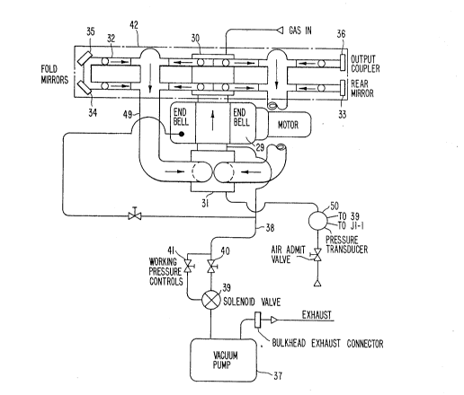
Fig. 2 is a schematic diagram of a gas laser
with the fluid flow control apparatus of Fig. l; and
Fig. 3 is a diagram of the electrical system
of the fluid flow control apparatus of Fig. 1.
Best Mode for Carry Out The Invention
The laser fluid control apparatus 1 of the
invention as illustrated in Fig. 1 is for precisely
controlling the fluid, in this case gas, supplied to a
laser from a supply of gas. The apparatus 1 comprises
respective sources of gases, namely He, N2 and CO2 as
identified by the reference numerals 2, 3 and 4 in
Fig. 1. Other gases or fluids could, of course, be
used depending on the type of laser and its operating
re~uirements. The gases are conveyed through
respèctive fluid passages in corresponding bulk head
connectors 5, 6 and 7 of a laser control cabinet.
Filters 10, 11 and 12 are provided for filtering the
respective gases.
The gases move through their respective gas
lines to a manifold 13. Individual pressure switches
14-16 are located in the respective fluid passages
within the manifold 13. The switches are adapted to
close if the pressures of the incoming gases do not
- 8 - 131 1040
exceed a required minimum. The laser operator is thus
alerted to the problem of a low pressure supply of a
particular gas and can correct the problem as by
hooking up a new cylinder of the pressurized gas.
Regulators 18, 19 and 20 with gauges or electronic
readouts are provided in each gas line downstream of
the manifold 13 for adjustably reducing the pressures
of the incoming gases to a workable, predetermined
level.
Solenoid valves 22, 23 and 24 provided in the
He, N2 and C02 gas lines downstream of the respective
regulators 18-20 open and close the gas lines for
controlling the flow of the gases toward the laser.
Metering units 25, 26 and 27 in the gas lines below the
solenoid valves 22, 23 and 24, determine the
permissible maximum flow rates of the respective gases
toward the laser. The metering units may, for example,
be flow valves with adjustable throttles, adjustable
orifice metering units such as an iris or an adjustable
needle type valve or some other metering means which
permit adjustment of the flow. Alternatively, the
metering units may be fixed orifice flow valves wherein
the orifice si~e is constant and the line pressure is
varied as with a regulator to effect adjustments in the
flow. The three gases, He, N2 and C02 are mixed
downstream of their respective metering units at a
mixer shown schematically at 2~. The mixed gases are
then conveyed to an essentially closed gas loop 49 of
the laser 42 within which the gases are circulated. In
other types of lasers an open loop fluid circuit could
be employed. The closed loop 49 includes a resonator
9 - 1~1 10~0
32, shown schematically in Fig. 2, wherein the gas is
excited thereby producing a laser beam. The gas is
circulated by a compressor 29 such as a ~oots blower or
turbine. Heat exchangers 30 and 31 are provided on
respective sides of the blower 29 for cooling the
circ,ulating gas. This type of forced transport
molecular gas laser is well known as evidenced by
assignees' U.S. Patent No. 4,~22,675, for example. The
gas is electrically or otherwise excited in the cavity
32 to cause it to lase. The light is reflected within
the cavity 32 by means of a rear mirror 33, fold
mirrors 34 and 35 and an output coupler 36 which is
partially transmissive for releasing laser light from
the resonator 32.
The laser gases circulating through the
resonator 32, heat exchanger 30, compressor 29 and heat
exchanger 31 are maintained at a relatively low
operating pressure, e.g., a small fraction of an
atmosphere such as 85 Torr by means of a vacuum pump
37. The pump 37 is connected to the essentially closed
loop 49 of the laser by means of gas line 38 through a
working pressure control valve 39 which is operated by
means of a solenoid for exhausting gas from the closed
laser loop through either a flow control valve 40 or a
flow control valve 41. The two valves 40 and 41 permit
different rates of exhaustion of gas from the laser by
the vacuum pump 37. The working pressure control valve
39 switches between the two control valves 40 and 41 to
maintain the laser system working pressure at a
predetermined, substantially constant value during the
operation of the laser. One of the valves 40 or 41 has
1 ~1 1 04Q
-- 10 --
a higher rate of exhaustion than the maximum flow of
yas to the laser to permit a lowering of the pressure
in the loop 49 even as gas is fed into the loop by the
fluid control apparatus. The operation of the valve 3g
to select either control valve 40 or 41 is controlled
in response to the output of a gas pressure sensor 50
in the closed loop 49. This solenoid valve 39 could
also be controlled by sensor 50 or another sensor in
the loop 49.
A diagram of the electrical system for the
laser gas flow control apparatus 1 is shown in Fig. 3
of the drawings. The control system permits the
operation to select a high volume of the gas to be
supplied to the laser as for example when the laser is
cold or high power is required, and a reduced volume to
the laser for economy at other times and/or after a
predetermined warm-up period of, for example, 10
minutes. The more economical, reduced flow can be
selected by the user of the laser before or during
operation of the laser. The operator can also select
the composition by adjusting the relative flows of the
several qases. Referring to Figs. 2 and 3, in
operation of the laser fluid flow apparatus 1, when the
laser 42 is first started, the vacuum pump 37 removes
the atmosphere from the vacuum circuits. When a vacuum
set point is reached, a pressure sensor 50 applies an
electrical signal of, for example, 15 volts to J1-1 for
initiating gas flow as discussed below. This
triggers a 10-minute timer 43 whose output 'la" goes
high. This high output is applied to OR gate 1 or OR
gate 2 to cause the outputs to go high. The high
outputs of the OR gates 1 and 2 are in turn,
-
æ~
1 31 1 040
applied to blpolar NPN transistors 47 and 48 to turn
them on to allow current to flow through the solenoid
coils Sl and S2, respectively. Current flow through Sl
turns on gas admit solenoid va:Lves 22 and 24 for helium
and carbon dioxide (e.g., see Fig. l); and current flow
through coil S2 turns on the gas admit solenoid valve
23 for N2. When the laser reaches its operating
pressure as sensed by pressure sensor 50, a high
voltage or other form of excitation is turned on and a
laser beam is produced within the resonator 32 and
emitted through the output coupler 36. The 10 minute
timer 43 continues feeding a high volume of the ~as,
for example, the total gas flow of the mixed gases is
4QO liters per hour, into the laser as the laser
warms-up. This achieves a fast warm-up of the laser.
Applicants have found that such a high volume of the
gas into the laser can reduce warm-up time of the laser
as compared with lower volum~ The high volume of
gas flow per hour is a rich mix which not only provides
the quickest warm-up of the laser, but also the highest
power output of the laser. However, for most
applications of the laser this rich a mixture is not
necessary. Lower volumes of the gas can be used with
only slight loss of power.
At the end of the 10-minute period of
warm-up, the timer 43 output "a" goes low and gas flow
to the laser is stopped as each of the solenoid valves
22, 23 and 24 is closed by stopping current flow
through coils Sl and S2. At this time OR gate 3
triggers an OFF timer 44 jwhich has a -Trig triggered
by a low output from OR gate 3) whose output "d" goes
v~
- 12 -
high for a short period, 5 seconds, for example, as set
by the timer 44. At the encl of the 5 second off period
of the OFF timer 44, "d" goes low triggering an
on-timer 45 ~which has a -Trig triggered by a low
output from OFF timer 44) for again actuating the flow
of both helium and carbon dioxide and triggering an
on-timer 46 (which also has a -Trig triggered by a low
output from OFF timer 44) for actuating the flow of N2
through OR gates 1 and 2, transistors 47 and 48 and
coils Sl and S2.
The time periods during which the ON timers
45 and 46 remain on can be adjustably selected by the
operator or other control by actuating one of the
switches 3-6 on the control panel of the apparatus. If
desired, separate switches could be provided for
setting each of the ON timers 45 and 46 differently
before operation of the laser. As shown in Fig. 3,
four settings are provided on each on-timer which
correspond to time periods for gas flow when the
solenoid valves are open of 5 seconds, 3.8 seconds, 2.4
seconds and 1.3 seconds, respectively. During the time
period of the ON timers 45 and 46, the respective gas
admit solenoid valves 22, 23 and 24 are actuated to
open the fluid passages and provide gas to the laser.
They will remain open for the precise on-times which
have been selected. After the ON timers have timed
out, the outputs "c" and "e" thereof will go low and
output "b" of OR gate 3 will then go low and trigger
the OPF timer 44 again. This on-off operation
continues in order to provide a precise control of the
gas admitted by solenoid valves 22, 23 and 24 for
- 13 - 131 10~
optimizing gas economy and laser perfoxmance. The
volume of the fluid supplied to the laser is of course
a function of the relative duty cycle or frequency of
operation of the respective timers.
In the disclosed embodiment the total reduced
volumP of fluid supplied after warm-up, when the ON
timers 45 and 46 are set to have a 5 second timing
period, is 200 liters per hour, at 3.8 seconds the flow
rate is 150liters per hour, at 2.4 seconds the volume is 100
liters per hour and at 1.3 seconds the volume is 50
liters per hour. These various flows occur while the
off timing period of timer 44 remains set at 5 seconds.
In the illustrated arrangement, the ~FF timer
44 is turned on by a negative "b" (b= 0). A signal of
24 volts passes through the electrical coils Sl and S2
between 1 and 2 and between 3 and 4 for actuating the
solenoid valves when the NPN transistors 47 and 48
become conductive in response to the outputs of the
respective OR gates 1 and 2 as shown in the diagram of
Fig. 3. Of course, these details are for purposes of
illustration only, and other arrangements for
triggering the timers and solenoids could, of course,
be made.
Jl-2 is a pulse/continuous wave mode select
switch provided on the control panel of the apparatus.
When continuous wave laser emission is selected, it
allows the N2 solenoid valve to be on a little longer
than the He and C02 solenoi~ valves as the time periods
of the on-timer 46 correspond to 5.5 seconds, 4.2
seconds, 2.6 seconds and 1.4 seconds, respectively,
instead of the aforemantioned time periods. This
14 - 131 1040
changes the composition of gas mix supplied to the
laser without substantially changing the volume of the
flow to thereby provide increased power for CW
operation.
5From the above discussion of the disclosed
embodiment of the invention, it is seen that the fluid
flow control apparatus of the invention allows the
laser operator to program the apparatus by selecting a
predetermined schedule of volumes of gas and/or gas
10compositions to be supplied to the laser during its
operation. This enables the operator to operate the
laser at any gas consumption that is desired from for
example, 400 liters per hour down to a minimum level of
gas consumption for laser operation. Variations of the
15volume of gas and/or composition can be predetermined
before operation of the laser and in addition
adjustments can be readi.ly made in a precise manner
during the operation of the laser. The invention
allows the operator to cover up for vacuum leaks, e.g.,
20air leaking into the system, reduce warm-up time of the
laser, reduce gas consumption and employ different gas
mixes to be used to optimize the laser performance.
Moreover, the changes in the volume of fluid and
composition can be made without concern for the laser
25operating fluid pressure which remains substantially
constant because of the pressure control apparatus of
the invention.
While we have shown and described one
embodiment in accordance w.ith the present invention, it
30is understood that the same is not limited thereto, but
is susceptible to numerous changes and modifications as
-15- 1~1 1040
known to those skilled in the art. The terms fluid and
gas as used herein are understood to encompass a single
fluid or gas, as well as mixtures of several fluids or
gases. The particular pressures and volumes or flows
referred to here are not limiting, but are merely cited
as examples of the operation of the fluid flow control
apparatus and method of the invention. It is also
envisioned that the method of the invention could be
accomplished using a suitably programmed computer or
microprocessor. The invention is applicable to lasers
other than the specific type disclosed herein.
Therefore, we do not wish to be limited to the details
shown and described herein, but intend to cover all
such changes and modification as are encompassed by the
scope of the appended claims.