Note: Descriptions are shown in the official language in which they were submitted.
I J~ 5
BACKGROUND OF THE INVENTION
Field of the Invention
The present invention relates to an apparatus for
recording and/or reproducing an information with a plurality
of heads arranged on a rotary drum.
Description of the Prior Art
.
In a video tape recorder (hereinafter simply referred to
as VTR) of l ~or 1.5) rotary head type using a magnetic tape
of l-inch wide, that is, a VTR using a so-called SMPTE type C
format, two rotary heads are mounted on a rotary drum, this
rotary drum is rotated at a revolution rate of one rotation
pe~ ~ne field and a magnetic tape is obliquely wrapped around
the peripheral surface of this rotary drum at an angle of
substantially 360 degrees and transported at a predetermined
speed. Of the above mentioned two rotary heads, the video
signal is recorded by one rotary head during its video
period, while a vertical synchronizing signal is recorded by
another auxiliary head during the synchronizing period in
which the former rotàry head is detached from the magnetic
tape.
By the way, in such a format, if a reproduced signal is
processed by a so-called time base corrector, even when the
signal in the synchronizing period is dropped, the normal
video signal can be reproduced without problem if the signal
in the video period is obtained. Therefore, it may be
considered that in the above mentioned format, instead of the
signal in the synchronizing period, a digital PCM
(pulse-code-modulated) audio signal be recorded on a skewed
track which is narrow in width.
Specifically, according to the prior art format as
- 2 -
1 31 1 045
mentioned above, the audio signal is recorded in the form of
an analog signal by a stationary or fixed head. In such an
analog recording, if especially the dubbing of such a
recorded analog audio signal is carried out repeatedly, the
analog audio signal is deteriorated considerably. While, if
the audio signal is recorded in the form of a digital signal,
it is possible to remove the problem that the audio signal is
deteriorated in the dubbing operation.
The above mentioned system is disclosed, for example, in
Japanese Laid Open Patent Application No. 57-119571.
However, in order that an audio data of one field
period is recorded in the synchronizing signal track, the
digital data must be time-base-compressed considerably and
this makes the signal processing very difficult. In
addition, the recording density (or packing density) becomes
large so that the above mentioned system is difficult to be
realized in the recording and/or reproducing system.
OBJECTS AND SUMMARY OF THE INVENTION
Accordingly, it is an object of this invention to
provide a novel recording and/or reproduicng apparatus which
can remove the defects encountered with the prior art
apparatus.
Another object of this invention is to provide a
recording and/or reproducing apparatus in which a plurality
of audio signal tracks are provided for a video signal track
of one field period.
Further object of this invention is to provide a
recording and/or reproducing apparatus in which a recording
and/or reproducing circuit can be made common to a plurality
of rotary heads, simplifying the construction of the
1~1 10~5
apparatus.
S~ill further object of this invention is to provide a
recording and/or reproducing apparatus in which even when the
number of the rotary heads is large, the number of rotary
transformers and the like can be reduced.
Yet further object of this invention is to provide a
recording and/or reproducing apparatus in which regardless of
rotary heads used, a signal can bé reproduced satisfactorily
by a playback head for a common signal.
According to one aspect of the present invention, there
is provided an apparatus for recording and/or reproducing a
signal on a tape recording medium with a plurality of rotary
recording and/or reproducing heads, the apparatus comprising:
a first input and/or output terminal for receiving and/or
deriving a video signal;
a second input and/or output terminal for receiving and/or
deriving an audio signal;
recording and/or reproducing circuit means including rotary
transformer means;
a first rotary recording and/or reproducing head connected to
said first input and/or output terminal through said
recording and/or reproducing circuit means and for recording
and/or reproducing said video signal on first parallel slant
tracks of a tape recording medium; and
a plurality of second rotary recording and/or reproducing
heads conneGted to said second input and/or output terminal
through said recording and/or reproducing circuit means and
for recording and/or reproducing said audio signal on second
parallel slant tracks of the tape recording medium; whereby a
plurality of said second parallel slant tracks are formed
131 10'15
correspondingly to one of said first parallel slant tracks.
According to another aspect of the present invention,
there is provided an apparatus for recording and/or
reproducing a signal on a tape recording medium with a
plurality of rotary recording and/or reproducing heads, the
apparatus comprising:
a signal input and/or output terminal for receiving and/or
deriving an input and/or output signal;
recording and/or reproducing circuit means including rotary
transformer means; and
a plurality of rotary recording and/or reproducing heads
connected to said signal input terminal through said
recording and/or reproducing circuit means and for recording
and/o~ reproducing a corresponding signal to said input
and/or output signal on the tape recording medium as a
plurality of parallel slant tracks which are formed during
one rotation of said plurality of rotary recording and/or
reproducing heads; whereby said plurality of rotary recording
and/or reproducing heads are arranged at predetermined angles
so as not to scan simultaneously said parallel slant tracks
and said recording and/or reproducing circuit means further
including switching means for conducting said input and/or
output signal to and/or from said plurality of rotary
recording and/or reproducing heads.
These and other objects, features and advan~ages of the
present invention will become apparent from the following
detailed description of the preferred embodiments taken in
conjunction with the accompanying drawings, throughout which
like reference numerals designate like elements and parts.
1 3 ~ I O ~ 5
B~IEF DESC~IPTION OF TH~ DRAWINGS
Fig. 1 is a schematic representa~ion showing a track
pattern formed on a magnetic tape according to the present
invention;
Fig. 2A is a plan view of a rotary head used in a first
embodiment of this invention;
Fig. 2B is a plan view of a rotary head used in a second
embodiment of this invention;
Fig. 3 is a systematic block diagram showing a recording
and/or reproducing system in which the rotary head of the
first embodiment is used;
Figs. 4A to 4~ are timing charts respectively used to
explain the operation of the embodiment of the invention
shown in Fig. 3;
Fig. 5 is a systematic block diagram showing a recording
and/or reproducing system in which the rotary head of the
second embodiment is used;
Figs. 6A to 6M are timing charts respectively used to
explain the operation of the embodiment of the invention
shown in Fig. 5;
Fig. 7 is a block diagram showing a reproducing system
of a third embodiment of the invention;
Fig. 8 is a circuit diagram showing an embodiment of a
light receiving circuit shown in Fig. 7;
Figs. 9A to 9C are schematic diagrams respectively
showing a rotary head used in the third embodiment shown in
Fig. 7;
Fig. 10 is a block diagram showing an embodiment of a
signal processing circuit according to the present invention;
Figs. llA to llC (they are separately formed for
1 31 1 ~45
convenience sake of sheet of drawing) are timing charts
respectively used to e~plain the recording and/or reproducing
operation of the apparatus according to the present
invention; and
Figs. 12A and 12B (they are separately formed for
convenience sake of sheet of drawings) are timing charts
respectively used to explain a monitor playback operation and
an operation in an EE (electronic edition) mode.
DESCRIPTION OF THE PREFERRED EMBODIMENTS
Referring now to the attached drawings, the present
invention will hereinafter be described in detail.
Particularly, in the first embodiment, the present invention
is applied to a recording and/or reproducing apparatus in
which an audio signal is pulse-code-modulated (PCM) and
recorded and/or reproduced by a video tape recorder
(hereinafter referred to as VTR) using a magnetic tape of
l-inch wide.
In a VTR having 1 ~or 1.5) rotary head using a magnetic
tape of l-inch wide, that is, in a VTR having a so-called
SMPTE-type C format, as shown in Fig. 1, a video track 2 on a
magnetic tape 1 is formed with a pitch of, for example,
0.1823 mm and a PCM audio track 3 of about 60~m wide is
formed on a prior art synchronizing track by 3 tracks (A to C
channels) per one pitch of the video track 2. The length of
the PCM audio track 3 is about 16H (H is the horizontal
scanning period of the NTSC system). In the case of the NTSC
system, two channels ~A and B channels) or all the three A to
C channels are used, while in the case of the PAL system and
SECAM system, the head scanning speed is relatively low so
that three of A to C channels are all employed. Analog audio
1 31 1 01l~5
tracks 4 to 6 formed on the upper ancl lower side edges of the
magnetic tape 1 by a fixed head and a CTL (control) track 7
formed under the video track 2 by a fixed head are formed
with track patterns same as those in the prior art.
Fig. 2A is a plan view illustrating a first embodiment
of a head drum 8 according to the present invention.
Referring to Fig. 2A, to a peripheral surface of an upper
drum 8U, there are mounted 12 heads of a video signal
record/reproduce head 9, PCM audio signal record heads lOa to
lOc of A to C channels, an erase head ll, PCM audio signal
preceding reproduce heads 12a to 12c, a dynamic tracking head
13 for a special reproduction of a video signal and PCM audio
signal monitor heads 14a to 14c along the rotation direction
R of the head drum 8 with a predetermined angular distance,
for example, an angular spacing of 30.
The PCM audio signal record heads lOa to lOc, the
preceding reading PCM audio signal reproduce heads 12a to 12c
and the PCM audio signal monitor heads 14a to 14c are
respectively mounted integrally on head bases 10, 12 and 14.
In order to simultaneously reproduce the PCM audio track 3 of
3 channels A to C, the head chip of each channel has a step
difference in the direction of the track width.
Fig. 2B is a plan view illustrating a second embodiment
of the head drum 8 according to the present invention. As
illustrated in Fig. 2B, the PCM audio signal record heads lOa
to lOc, the preceding reading PCM signal reproduce heads 12a
to 12c and the PCM audio signal monitor heads 14a to 14c,
which are each integrally mounted on the head bases 10, 12
and 14 respectively in the example shown in Fig. 2A, are
separately located with a predetermined angular spacing along
I J 1 1 045
the rotation direction R of the upper drum 8U. The length of
the PCM audio track 3 shown in the track pattern of Fig. 1 is
about 1/18 of the wnole periphery of the head drum 8 and
corresponds to about ~0 in a rotation angle of the rotary
head drum. Each spacing of the respective heads lOa to lOc;
12a to 12c; and 14a to 14c is selected to be more than 20
(about 30 in the embodiments of the invention). In
addition, in order to form parallel slant tracks of 3
channels, they are arranged to have small step differences of
heights a, b and c (in the track width direction).
According to this arrangement, when the parallel slant
tracks of the A to C channels are formed, the respective
heads lOa to lOc, 12a to 12c and 14a to 14c are prevented
from simultaneously ~in an overlapping fashion) scanning the
PCM audio track 3 from a time standpoint so that the signal
processing system (recording and/or reproducing circuit) can
be formed as one channel and carries out the time division
operation (serial processing).
The preceding recording PCM audio signal reproduce heads
12a to 12c are used to reproduce the PCM audio signal at the
timing preceding (preceding, for example, by 3 3l tracks) upon
an edition so as to make the replacing operation of the audio
signal easy. The PCM audio signal monitor heads 14a to 14c
are used in the simultaneous recording and reproducing and
referred to as a confidential head.
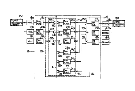
Fig. 3 is a block diagram of a PCM audio signal record
and/or reproduce system used in a case ~here the head drum
shown in Fig. ~A is used. Referring to Fig. 3, serial
channel data A to C derived from an audio data signal
processor 15a during one field period as shown by a timing
1 3 1 1 0 ~5
chart in Fig. 4A in the recording side are converted in code
and modulated by modulators 16a to 16c, which are provided
for each channel, and then introduced into a VTR unit 17 as
parallel and simultaneous data as shown in Figs. 4B to 4D.
The parallel data are supplid through recording amplifiers
18a to 18c and through rotary transformers 20a to 20c of a
rotary head unit 19 to the recording heads lOa to lOc.
Reproduced signals are derived ~rom the monitor heads 14a to
14c or the preceding PCM audio signal reproduce heads 12a to
12c at the timings shown in Figs. 4E to 4G or Figs. 4H to 4J.
These reproduced signals are amplified by pre-amplifiers 21a
to 21c and 22a to 22c and fed through 6-channel rotary
transformers 23a to 23c and 24a to 24c to change-over
switches 25a to 25c which are controlled i,n, response to a
switching signal applied thereto from an input terminal 26.
The reproduced signals, which are changed-over to the
3-channel reproduced signals by the change-over switches 25a
to 25c, are supplied through RF equalizers 27a to 27c to
demodulators 28a to 28c in which they are converted to a
serial signal shown in Fig. 4K. This serial signal is fed to
a signal processing circuit 15b.
Fig. 5 is a block diagram of a PC~ audio signal
recording and/or reproducing system using the head drum shown
in Fig. 2B. Referring to Fig. 5, in the recording system
thereof, the serial audio output data A to C shown in a
timing chart of Fig. 6A derived from the signal processing
circuit 15a are processed by a single modulator 16 and then
distributed to 3 channel signals by a distributing switch
30 as shown in Figs. 6B to 6D. The three channel signals are
supplied through the recording amplifiers 18a to 18c and the
-- 10 --
1 3 1 1 045
rotary transformers 20a to 20c to the recording heads lOa to
lOc .
While, in the reproducing system, from the monitor hèads
14a to 14c and the preceding reading reproduce heads 12a to
12c, there are derived reproduced signals A to C shown in
Figs. 6E to 6G and Figs. 6H to 6J which are not overlapped
from a time standpoint and then fed to playback amplifiers
21a to 21c and 22a to 22c. In this case, they are supplied
thereto as follows. That is, at first, the signal on the
track A is reproduced by the head 14a as shown in Fig. 6E,
then the signal on the track B is reproduced by the head 14b
as shown in Fig. 6F and next the signal on the track C is
reproduced by the head 14c as shown in Fig. 6G. After the
playback operations are carried out by the heads 14a, 14b and
14c, the signal on the track A is reproduced by the reproduce
head 12a as shown in Fig. 6H, then the signal on the track B
is reproduced by tne reproduce head 12b as shown in Fig. 6I
and last, the signal on the track C is reproduced by the
reproduce head 12c as shown in Fig. 6J. The reproduced
signal by each head is obtained in a range of about 20 in a
rotation angle of the upper drum 8U. The preceding read
outputs or the monitor outputs are selected by the
change-over switches 25a to 25c and supplied through rotary
transformers 31a to 31c to a selection switch 32 in which
they are sequentially selected and then converted to a serial
data signal shown in Fig. 6K or 6L. The serial signals A to C
are processed in a serial fashion by a single RF equalizer 27
and a demodulator 28 to be a serial signal shown in Fig. 6M,
which is then inputted to the signal processing circuit 15b.
In this case, the switching signal is supplied to the
1J1 1045
change-over switches 25a to 25c f~om the input terminal 26
through a slip ring 33 provided between the upper drum 8U and
a lower drum 8L. Whereas, a switching control signal is
supplied to the change-over switch 32 from an input terminal
34. Since the reproduced signals obtained at the heads 14a,
14b and 14c are displaced in timing as shown in Figs. 6E to
6G, the change-over switching circuit 32 is changed-over by
the switching signal supplied thereto from the input terminal
34 such that its movable contact is sequentially connected to
its fixed contacts connected to the rotary transformers 31a,
31b and 31c during the period in which each reproduced signal
is obtained. Thus, within one field period, the signals on
the tracks A, B and C are reproduced through the RF equalizer
27 as shown in Fig. 6K. The reproduced signals obtained from
the heads 14a, 14b and 14c as described above are used for
monitoring in the recording mode. Since the reproduce
signals obtained from the respective heads 12a, 12b and 12c
are displaced as shown in Figs. 6H, 6I and 6J, similarly to
the playback operations of the heads 14a, 14b and 14c, the
movable contact of the change-over switch 32 is changed-over
at every reproducing period, whereby to reproduce the signals
of the respective channels A, B and C through the equalizer
27 within one field period after the playback period of the
above mentioned heads 14a to 14c as shown in Fig. 6L. The
reproduced signals thus obtained from the reproduce heads
12a, 12b and 12c are supplied to the reproducing circuit
system of the apparatus.
When the reproduced signals obtained by the heads 14a,
14b and 14c and the reproduced signals obtained by the heads
12a, 12b and 12c are all reproduced, after the playback
- 12 -
1 J 1 1 ~4C)
period in which the signals are reproduced by the heads 14a,
14b and 14c are ended, the movable contacts of the
change-over switches 25a, 25b and 25c are switchably changed
in position from the fixed contacts at the sides of the
playback amplifiers 21a, 21b and 21c to the fixed contacts at
the sides of the playback amplifiers 22a, 22b and 22c. When
the movable contacts of the switches 25a, 25b and 25c are
changed in position as mentioned above, all the signals
reproduced by the heads 14a, 14b and 14c and the reproduce
heads 12a, 12b and 12c a~e obtained as shown in Fig. 6M. The
reproduced signals thus obtained are supplied to the
reproducing circuit system and the like and thereby processed
properly.
Since the multi-channel signals, which are originally
recorded in the parallel PCM audio tracks 3, are processed in
a serial fashion, the circuit arrangement of the record
and/or reproduce circuit can be simplified considerably.
Alternatively, the recording amplifiers 18a to 18c are
formed into a single recording amplifier and at the next
state the signals may be distributed into the heads of 3
channels. Further, if a head change-over switch ~used to
branch one channel into 3 channels) is provided within the
upper drum 8U ~rotary drum), the rotary transformers ~Oa to
20c can be formed into a single rotary transformer to thereby
transmit the signal via one transmission channel in a time
division manner. Similarly in the reproducing system, a head
change-over switch for converting 3 channels into 1 channel
is provided within the upper drum 8U to thereby integrate the
transmission lines of the reproduced signals into one
transmission line and the rotary transformers can be formed
- 13 -
1 3 1 1 0 ~ 5
into the rotary transformer of one channel ~2 circuits for
recording and reproducing modes). Furthermore, if the record
and/or reproduce head is used, it is sufficient that the
rotary transformer be provided for one circuit.
According to the present invention as set forth above,
when a plurality of PCM audio tracks are formed by every one
rotation of the head drum and recorded and/or reproduced, a
pluarlity of rotary heads scan the tracks without overlapping
in timing and the record and/or reproduce circuit processes
the serial signal so that the circuit arrangement can be
simplified, the manufacturing cost can be reduced and the
reliability can be improved.
In the circuit arrangement shown in Fig. 5, the upper
drum 8U and the lower drum 8L are connected through the three
rotary transformers 31a, 31b and 31c which supplies the
reproduced signals and the slip ring 33 through which the
switching signal is supplied. In addition, including the
rotary transformers used to connect the audio signal
recording head and the video signal record and/or reproduce
head, the number of the rotary transformers provided between
the upper drum 8U and the lower drum 8L is increased
vehemently. Thus, a large space must be used to provide the
rotary transformers and hence the rotary head drum assembly
becomes large in size.
Fig. 7 is a systematic block diagram showing a third
embodiment of the present invention which can overcome the
above mentioned defects. In Fig. 7, like parts corresponding
to those of Fig. 5 are marked with the same references and
will not be described. Referring to Fig. 7, the reproduced
signals from the heads 14a, 14b and 14c and the reproduce
- 14 -
IJ I 1 045
heads 12a, 12b and 12c provided within the upper drum 8U are
supplied through the amplifiers 21a, 21b and 21c and 22a,
22b, 22c to one terminals of switches 35 to 40. When the
switches 35 to 40 are closed, the reproduced signals obtained
at the other terminals thereof are supplied to the side of
the upper drum 8U of a single rotary transfomer 47. The
switches 35 to gO are turned on and off by light receiving
circuits 41 to 46 which will be described later. The
reproduced signal obtained at the side of the lower drum 8L
of the rotary transformer 47 is supplied to the playback
equalizer 27. In the lower drum 8L, a light emission diode
48 is connected between a control signal input terminal 49
and a control signal output terminal 50 and the light
emission diode 48 is arranged to always emit a light during
the playback mode.
Subsequently, the circuit arrangements of the light
receiving circuits 41 to 46 which control the switches 35 to
4~ will be described with reference to Fig. 8. In this case,
the light receiving circuit 41 will be described by way of
example. In the light receiving circuit 41, an emitter of a
photo transistor 41a is connected to the base of an NPN
transistor 41b and grounded via a resistor 41c. The
collector of the photo transistor 41a is connected to a drive
signal input terminal 41d. Further, the emitter of the
transistor 41b is grounded and the collector thereof is
connected through a resistor 41c to the drive signal input
terminal 41d and to the switch 35. With the circuit
arrangement thus made, when the photo transistor 41a receives
a light, this photo transistor 41a is turned on. When this
photo transistor 41a is turned on, the transistor 41b is also
- 15 -
131 1045
turned on so that the signal ~rom the drive signal input
terminal 41d is supplied to the switch 35, placing the switch
35 in its closed state. Whereas, when the photo transistor
41a does not receive the light, the photo transistor 41a and
the transistor 41b are not turned on so that no signal is
supplied to the switch 35, thus the switch 35 being placed in
the open state. Other light receiving circuits 42 to 46 are
constructed similarly.
The arrangements of the respective members on the rotary
head drum will be described below with reference to Figs. 9A
to 9C. The respective magnetic heads 9 to 14c are mounted on
the upper drum 8U with an equal angular spacing (at every
30) as illustrated in Fig. 9A, similarly to the example
shown in Fig. 2B. Referring to Fig. 9A, just after the heads
14a, 14b and 14c and the digital audio signal reproduce heads
12a, 12b and 12c, there are provided the photo transistors
41a to 46a of the respective light receiving circuits 41 to
46 and the respective light receiving sections of the photo
transistors 41a to 46a are opposed to the lower drum 8L. The
light emission diode 48 is mounted on the lower drum 8L such
that as shown in Figs. 9B and 9C, the light emission diode 48
is secured within a housing 48a whose open end is faced to
the upper drum 8U by, for example, a rotation angle of 26.
Thus, it becomes possible to obtain a rotation angle of 23
which is required in the playback.
With this arrangement, when the digital audio signal is
reproduced, the photo transistors 41a to 46a mounted on the
upper drum 8U sequentially move over the light emission diode
48 mounted on the lower drum 8L. While the photo transistors
41a to 46a receive the light emitted from the light emission
- 16 -
diode 48, the switches 35 to 40 connected to the photo 1 3 1 1 0 4 5
transistors 41a to 46a are closed. Since the light emission
diode 48 is housed in the housing 48a so as to transmit the
light to the upper drum 8U through a range of 26 in a
rotation angle of the head drum and the respective heads are
mounted on the upper drum 8U with the angular spacing of 30,
only one of the photo transistors 41a to 46a can receive the
light emitted from the light emission diode 48 or none of
them can receive it. On the other hand, the digital audio
signals are reproduced by the heads 14a, 14b and 14c and the
reproduce heads 12a, 12b and 12c such that they are displaced -~
in timing by the predetermined interval as shown in Fig. 6.
In addition, the reproduced signals by the respective heads
are obtained in a range of 23 in a rotation angle of the
head drum. Accordingly, if the respective heads 14a to 14c
and 12a to 12c are positioned such that the angular range of
23 in which the reproduced signals of the respective heads
are obtained falls within the angular spacing of 26 in which
the photo transistors 41a to 46a receive the light emitted
from the light emission diode 48, the switches 35 to 40 are
respectively closed by the light emitted from the light
emission diode 48 during the period in which the reproduced
signals of the respective heads are obtained. When the
switches 35 to 40 are closed as described above, the
reproduced signals from the respective heads 14a to 14c and
12a to 12c are sequentially obtained at the side of the upper
drum 8U of the rotary transformer 47 as shown in Fig. 6M.
The reproduced signals are supplied through the side of the
lower drum 8L of the rotary transformer 47 to the playback
equalizer 27.
- 17 -
According to this embodiment, since the reproduced I J~l Oa5
signal is supplied through one rotary transformer 47 to the
side of the lower drum 8L from the side of the upper drum 8U
and the switches 35 to 40 are controlled so as to open and
close by the light emission diode 48 provided on the lower
drum 8L, it is not necessary to supply the signal used to
control the switches 35 to 40 by using the rotary
transformer, the slip ring and the like. Thus, the number of
the rotary transformers and the slip ring between the upper
drum 8U and the lower drum 8L can be reduced considerably as
compared with the prior art. Therefore, the rotary head
assembly can be miniaturized and simplified in construction.
Further, the drive signals supplied to the light receiving
circuits 41 to 46 can be used commonly as the drive signals
which drive the amplifiers 21a to 21c and 22a to 22c. Thus,
the number of the signal supply lines between the upper drum
8U and the lower drum 8L can be prevented from being
increased.
By the way, when the signal is recorded and/or
reproduced in a digital fashion, a time delay occurs in the
signal due to an A/D ~analog-to-digital) conversion, a D/A
(digital-to-analog) conversion, an error correction and the
like upon recording and reproducing. When the signal is
processed at the unit of one field period, this time delay
becomes one field period in the case of the recoLding mode,
while it becomes more than one field period due to the error
correction and the like in the case of the reproducing mode.
For this reason, in the afore-mentioned recording apparatus,
the record heads and the reproduce heads are provided
independently and the reproduce heads are located to precede
- 18 -
the record head in position by the amount corresponding to ~ 0 4 5
this time delay so that the timing at which the PCM audio
signal is reproduced can colncide with the timing in the
recording mode.
An example of the signal processing circuit 15 of the
recording and/or reproducing apparatus according to the
present invention will be described with reference to Fig.
10 .
Referring to Fig. 10, an analog audio signal applied to
an input terminal 51 is supplied through an I/O (input and
output) circuit 52 to an A/D converter 53 and thereby
converted to a digitial data. This digital data is supplied
to a data bus 54 and the data on the data bus 54 is supplied
to a memory 55 in which it is stored.
Further, the data stored in the memory 55 is supplied
through a data bus 56 to an encoder 57 and thereby encoded
such as a predetermined error correction code is added, the
data is re-arranged ànd so on. The data from the memory 55
is also supplied to the modulator 16 and thereby modulated.
The PCM audio data formed by the modulated data is supplied
through the recording amplifiers 18a, 18b and 18c and the
rotary transformers 20a, 20b and 20c (shown in Fig. 3 but not
shown in Fig. 10 for simplicity of drawing) to the recording
heads lOa, lOb and lOc and thereby recorded on the slant
tracks having the narrow width and corresponding to the
synchronizing signal track on the above mentioned magnetic
tape 1. Further in the reproducing mode, the signals
reproduced from the magnetic tape 1 by the reproduce heads
12a, 12b and 12c or the heads 14a, 14b and 14c are supplied
through the playback amplifiers 21a, 21b and 21c or 22a, 22b
-- 19 --
~ 7l 10~5
and 22c to the demodulator 28 in which the recorded digital
data is demodulated. The demodulated data is supplied to
data buses 58 and S9 and the data on the data buses 58 and 59
are supplied to the memory 55 and also to first and second
decoders 60 and 61. The address of the data detected by the
demodulator 28 is supplied through an address bus 62 to the
memory 55.
Then, the data decoded such as re-arranged,
error-corrected and so on is supplied from the memory 55 to
the data bus 54. The data on the data bus 54 is supplied to
a D~A converter 63 and thereby converted to an analog audio
signal. This analog audio signal is supplied through the I/O
circuit 52 to an output terminal 64.
A signal applied to an input terminal 65 for a digital
signal is supplied through an I/O circuit 66 to the data bus
54, while the signal on the data bus 54 is supplied through
the I/O circuit 66 to a digital signal output terminal 67.
Figs. llA to llC (they are separately formed for
convenience sake of sheet of drawing) are respectively timing
charts used to explain the recording and reproducing
operation of this apparatus shown. Throughout Figs. llA to
llC, longitudinal lines indicate the border lines between the
adjacent fields. Fig. llA shows the recording operation of
the apparatus. Referring to Fig. llA, the signal
A/D-converted during, for example, a field "0" is encoded
during the first half of a next field "1",
time-base-compressed and read out during the second half of
this field "1" and then recorded by the record heads 10a, 10b
and 10c. On the other hand, Fig. llB illustrates the normal
reproducing operation. Referring to Fig. llB, the signals
- 20 -
131 ~0,15
reproduced by the reproduce heads 12a, 12b and 12c at the
former half of, for example, a field ~-2" are decoded over
the period from the latter half of the field n-2" to the
former half of a next field n-ln, time-base-expanded during
the period of the next field "0", then D/A-converted and then
delivered.
Accordingly, in the above mentioned apparatus, when the
signals are derived during the same field "0", the reproduce
heads 12a, 12b and 12c must be located to precede the record
heads lOa, lOb and lOc by the amount of more than 3 field
periods. Then, in the case of the above mentioned apparatus,
since the mounting positions of the reproduce heads 12a, 12b
and 12c on the rotary drum precede those of the record heads
lOa, lOb and lOc by 90 in a rotation angle of the head drum,
the practical preceding amount is 3 4 fields.
However, in that case, according to the video tape
recorder using the so-called SMPTE type C format, in addition
to the inherent head 9 used to generally record and/or
reproduce the video signal, there is provided a dynamic
tracking ~hereinafter simply referred to as DT) head 13 which
is used to reproduce the video signal in the playback mode
with variable tape speeds. This DT head 13 is mounted on the
rotary drum at the position after the inherent record and/or
reproduce head 9 by 120 in a rotation angle of the head
drum. When the signal is reproduced by the DT head 13 which
is mounted with an angular spacing different from that of the
inherent head 9, the magnetic tape 1 is transported under the
state that it precedes the normal position by the 1/3 track
pitch so that the tracking of the PCM audio signal recorded
on the above mentioned synchronizing track is displaced and
- 21 -
thus the satisfactory playback can not be carried out. I J I ~ 0
To avoid this defect, it may be considered that another
set of reproduce heads for the PCM audio signal be provided at
an angle matched with 120. However, if there are provided
many heads, the construction of the rotary drum becomes
complicated and the signal processing system becomes also
complicated in circuit arrangement.
In that case, however, the tracks A, B and C of the PCM
signal are located at every 1/3 track pitch as described
above so that even when the magnetic tape 1 is transported
under the state that it precedes by 1/3 track pitch amount,
the tracks A, B and C can be reproduced equivalently by the
heads 12a, 12b and 12c. In this case, however, since the
head precedes 12a to 12c by the 1~3 track pitch, thè PCM
signals reproduced at the timing same as the normal timing
are reproduced from, for example, the tracks B, C and the
track A of the next field.
Then, as shown in the timing chart in Fig. llC, the
signal of the track A reproduced during the period of, for
example, the field n-2" is kept over the next field n-l" and
decoded together with signals of the tracks B and C
reproduced during the next field n-ln. Therefore, in order
to carry out the reproducing at the variable tape speed by
using the DT head 13 as shown in Fig. 10, the control signal
is supplied through a terminal 68 to an edition eontrol
circuit 69 and the control signal from the edition control
circuit 69 is supplied through an auxiliary bus line 70 to
the memory 55. In other words, in order to control the
memory 55 as above, the control signal applied to the
terminal 68 is supplied through the edition control circuit
- 22 -
69 to the memory 55. ~ 0 4 5
According to the apparatus as described above, when the
dynamic tracking head 13 is used, the same reproduce head can
be used to reproduce the PCM signal so that the PCM signal
can be recorded and/or reproduced by the simple arrangement.
In this case, the capacity of the memory 55 requires one
field amount more when the signal is reproduced by using the
dynamic tracking head 13.
In addition, the head arrangement on the rotary drum is
not limited to the above mentioned example.
By the way, when the digital audio signal is dubbed with
the same sampling frequency, there is caused no trouble.
However, when tne signal is dubbed in the mode of different
sampling frequencies, for example, the signal is dubbed from
the playback side having a frequency of, for example, 48 kHz
to the recording side having a frequency of 44.056 kHz or
when the digital signal is signal-processed via a transversal
filter such as a sampling rate converter and the like, there
will occur the time delay of one to several sampling periods.
However, the normal signal processing is carried out at the
unit of, for example, one field period as described above so
that there is a fear that the recording after the edition
will be obstructed from being carried out normally even when
the delay amount is very small.
Although as described above the reproduce heads 12a, 12b
and 12c are located to precede the record heads by the amount
of more than 3 field periods, one field period for the
A/D-conversion and the D/A-conversion and one field period
for the encoding upon recording and the recording are
required in practice but with respect to l 4- :field periods
- 23 -
131 10~-t5
for the reproducing and the decoding (error correction) in
the playbac~ mode, about one field is required in practice,
so that the remaining field of about 1/4 is an extra field.
For this reason, in the above mentioned timing charts, during
the period of about 1/4 field from the end of the decoding to
the start of the D/A-conversion, the digital data is kept in
the memory 55 only and placed in the stop mode.
Accordingly, when the data is signal-processed in the
above mentioned edition mode and the like, the data is read
out of the memory 55 at an earlier timing by the amount
necessary to the processing and thereby the time delay caused
by the signal processing can be removed. Specifically,
referring to the above mentioned block diagram of Fig. 10,
the reading of the data from the memory 55 is controlled by
the control signal from the edition control circuit 69, such
that in the normal playback mode, the data is read out from
the beginning of the next field, while upon edition, the data
is read at a time point preceding the beginning of the next
field. Thus, the signal-processing operation which causes
the time delay can be carried out without any time delay.
In this case, the reading operation from the memory 55
can be delayed until the end point of one field period
approaches immediately before the playback of the next field~
Consequently, it becomes possibile to remove a defect that
the video signal is delayed when the video signal, for
example, is signal-processed.
Fig. 12A is a timing chart used to explain the monitor
playback mode of the apparatus. Referring to Fig. 12A, a
signal A/D-converted during the period of, for example, the
field "O" is encoded in the first half of the next field "1",
1 7 1 1 0~5
time-base-co~pressed and read in the second half of this
period of the field "1" and then recorded by the record heads
lOa, lOb and lOc. The signal thus recorded is reproduced by
the monitor playback heads 14a, 14b and 14c during the first
half of the next field "2n. The signal reproduced is
decoded over the period from the second half of the field "2"
to the first half of the next field "3n, time-base-expanded
and read out during the period corresponding to the
succeeding one field and then D~A-converted. In other words,
in the monitor playback mode, it is not necessary that the
audio signal be synchronized with the video signal so that
the reading and the D/A conversion can be carried out
immediately.
Further, other mode in which the signal just before
being supplied to the record heads lOa, lOb and lOc is
demodulated and then monitored, that is, so-called EE
(electronic edition) mode will be described with reference to
the block diagram of Fig. 10. In order to realize the above
mode, there are respectively provided change-over switches 71
and 72 between the modulator 16 and the recording amplifiers
18a, 18b and 18c and between the demodulator 28 and the
play~ack amplifiers 21a, 21b, 21c and 22a, 22b, 22c. The
modulator 16 and the demodulator 28 are connected to the
movable contact of the change-over switches 71 and 72,
respectively, while the recording amplifiers 18a, 18b and 18c
and the playback amplifiers 21a, 21b, 21c and 22a, 22b, 22c
are connected to one fixed contacts thereof. The other fixed
contacts of the switches 71 and 72 are coupled together. The
change-over switches 71 and 72 are changed in position to the
other fixed contacts by the control signal from the edition
1 3 1 1 0 ~5
control circuit 69 in the ~E mode.
Fig. 12B is a timing chart used to explain the operation
of the apparatus in the EE mode. Referring to Fig. 12B, a
signal A/D-converted during the first half of, for example,
the field "O" is encoded during the first half of the next
field "l", time-base-compressed during the second half of
this field "l" and then read out. The signal thus read out
is supplied to the modulator 16 and further supplied through
the change-over switches 71 and 72 to the demodulator 28.
The demodulated signal is written again in the memory 55 and
then decoded during the period of the next field "2n.
The signal thus decoded is time-base-expanded and then read
out during the period corresponding to the succeeding one
field and then D/A-converted. In this case, the reading
operation of the data from the memory 55 is controlled such
that the timings of the reading and the D/A-conversion may
coincide with each other.
In consequence, by the monitor reproduced signal and
the reproduced signal in the EE mode, the timing displacement
relative to the EE mode and caused in response to the
distance from the record heads lOa, lOb and lOc to the
monitor reproduce heads 14a, 14b and 14c can be compensated
for. Thus, the monitor playback operation and the operation
in the EE mode can be carried out by the simple circuit
arrangement. Further, the comparison can be carried out
satisfactorily under the state that the time points of these
Signals are made coincident with each other.
In this case, the capacity of the memory 55 must be
increased by the amount of one field period for the purpose
of carrying out the operations in the monitor playback mode
- 26 -
I Jl IG~5
and the EE mode.
In addition, the present invention is not limited to the
above mentioned apparatus but can be applied to various
apparatus for recording and/or reproducing an audio signal,
particularly, a PCM audio signal by using a rotary head, an
apparatus such as a digital VTR for recording and/or
reproducing a video signal and an audio signal and so on.
The above description is given on the preferred
embodiments of the invention but it will be apparent that
many modifications and variation could be effected by one
skilled in the art without departing from the spirits or
scope of the novel concepts of the invention so that the
scope of the invention should be dètermined by the appended
claims only.
- 27 -