Language selection

Search

Patent 1311140 Summary

Third-party information liability

Some of the information on this Web page has been provided by external sources. The Government of Canada is not responsible for the accuracy, reliability or currency of the information supplied by external sources. Users wishing to rely upon this information should consult directly with the source of the information. Content provided by external sources is not subject to official languages, privacy and accessibility requirements.

Claims and Abstract availability

Any discrepancies in the text and image of the Claims and Abstract are due to differing posting times. Text of the Claims and Abstract are posted:

  • At the time the application is open to public inspection;
  • At the time of issue of the patent (grant).
(12) Patent: (11) CA 1311140
(21) Application Number: 569431
(54) English Title: ROTARY/RECIPROCATORY MOTION CONVERTER
(54) French Title: DISPOSITIF DE CONVERSION DU MOUVEMENT ROTATIF EN ALTERNATIF ET VICE VERSA
Status: Deemed expired
Bibliographic Data
(52) Canadian Patent Classification (CPC):
  • 74/63
(51) International Patent Classification (IPC):
  • F16H 21/16 (2006.01)
  • F04B 9/02 (2006.01)
  • F04B 47/02 (2006.01)
  • F16H 19/06 (2006.01)
(72) Inventors :
  • DARTNALL, WILLIAM JOHN (Australia)
  • LANGRIDGE, DAVID (Australia)
(73) Owners :
  • DARTNALL ENGINEERING & INNOVATION PTY. LTD. (Australia)
(71) Applicants :
(74) Agent: RICHES, MCKENZIE & HERBERT LLP
(74) Associate agent:
(45) Issued: 1992-12-08
(22) Filed Date: 1988-06-14
Availability of licence: N/A
(25) Language of filing: English

Patent Cooperation Treaty (PCT): No

(30) Application Priority Data:
Application No. Country/Territory Date
PI 2498 Australia 1987-06-15

Abstracts

English Abstract


ABSTRACT
This invention relates to a continuous rotary to
reciprocatory or reciprocatory to rotary motion converter
comprising a pair of wheels in spaced co-planar
relationship to each other and having an endless flexible
drive member received over them, a carrier located to both
sides of the drive member. The drive member supporting at
one location thereon a slider which extends to each side
of the drive member. The slider being slidably received
on the drive member to extend to each side thereof for
movement with the drive movement and transfers movement
relative to the axis extending between the wheels whereby
with movement of the drive member over the wheels said
carrier reciprocates between said wheels and said slider
reciprocates transversely on the carrier support means
being provided to support the slider at both sides of the
drive member from the carrier continuously throughout
movement of the carrier.


Claims

Note: Claims are shown in the official language in which they were submitted.

The embodiments of the invention in which an
exclusive property or privilege is claimed are defined as
follows:

1. A continuous rotary to reciprocatory or
reciprocatory to rotary motion converter comprising a pair
of wheels in spaced co-planar relationship to each other and
having an endless flexible drive member received over them,
a carrier located to both sides of the drive member, said
drive member supporting at one location thereon a slider
which extends to each side of the drive member, said slider
being slidably received on the carrier to extend to
each side thereof for movement with the drive member and
transverse movement relative to the axis extending between
the wheels whereby with movement of the drive member over
the wheels said carrier reciprocates between said wheels and
said slider reciprocates transversely on the carrier and support
means being provided to support the slider at both sides of
the drive member from the carrier continuously throughout
movement of the carrier.


2. A motion converter as claimed in claim 1 wherein
the slider is engageable with the carrier to each side of
the drive member through at least one roller rotatably
supported from the slider and received in the carrier for
said transverse movement.


11


3. A motion converter as claimed in claim 1 wherein
the slider is engageable with the carrier to each side of
the drive member through at least one slider block slidably
supported from the carrier for said transverse movement.


4. A motion converter as claimed in claim 1 or claim 2
wherein the wheels are supported from a base by a shaft
extending to at least one side of the respective wheel and the
portion of the carrier located to at least one side of the
carrier being formed with a gap to enable the carrier to
reciprocate past the shafts.


5. A motion converter as claimed in claim 3 wherein
the wheels are supported from a base by a shaft extending to
at least one side of the respective wheel and the portion of
the carrier located to at least one side of the carrier being
formed with a gap to enable the carrier to reciprocate past
the shafts.


6. A motion converter as claimed in claim 4, wherein
the support means comprises a guide member supported
adjacent to each wheel which is receivable in said gap on
said carrier moving past said shaft to its respective end
position said guide member being formed to receive the
slider in its passage across the gap.


12

7. A motion converter as claimed in claim 5, wherein
the support means comprises a guide member supported
adjacent to each wheel which is receivable in said gap on
said carrier moving past said shaft to its respective end
position said guide member being formed to receive the
slider in its passage across the gap.


8. A motion converter as claimed in claim 6 wherein
the guide member is capable of resilient movement with the
carrier in the direction of said axis when engaged with the
carrier.


9. A motion converter as claimed in claim 7 wherein
the guide member is capable of resilient movement with the
carrier in the direction of said axis when engaged with the
carrier.


10. A motion converter as claimed in any one of claim
5, 7 or 9 wherein said support means includes said slider
blocks being of sufficient length that the distance between
the mounting of the slider to the slider blocks and each
ends of the slider block is greater than the width of the
gap.


11. A motion converter as claimed in any one of claim 1
to 3 or 5 to 9 wherein the wheels are supported at spaced


13


locations on an elongate base and said carrier is guided by
the base for axial movement thereon.


12. A motion converter as claimed in claim 4 wherein
the wheels are supported at spaced locations on an elongate
base and said carrier is guided by the base for axial
movement thereon.


13. A motion converter as claimed in claim 11 wherein
the elongate base is formed of a channel or box shaped
section having inwardly directed flanges at the edges.


14. A motion converter as claimed in claim 12
wherein the elongate base is formed of a channel or box
shaped section having inwardly directed flanges at the
edges.


15. A motion converter as claimed in claim 13 wherein
the channel or box shaped section comprises a formed sheet
metal section.


14


16. A motion converter as claimed in claim 14 wherein
the channel or box shaped section comprises a formed sheet
metal section.

17. A motion converter as claimed in claim 13 wherein
the channel or box shaped section comprises an extruded
section.
18. A motion converter as claimed in claim 14 wherein
the channel or box shaped section comprises an extruded
section.

19. A motion Converter as claimed in any one of claim
13,15,16 or 17 wherein the carrier is guided by the inner
face of the channel shaped section by rollers mounted to be
carrier.

20. A motion converter as claimed in claim 17 or 18
wherein the wheels are adjustable on the carrier to vary the
degree of outward extension from the carrier.


21. A continuous rotary to reciprocatory motion
converter as claimed in any one of claim 1 to 3, 5 to 9, 12,13
15 to 18 wherein at least one wheel is driven to
cause reciprocation of the carrier.


22. A continuous rotary to reciprocatory motion
converter as claimed in claim 4 wherein at least one wheel
is driven to cause reciprocation of the carrier.


23. A Continuous rotary to reciprocatory motion
converter as claimed in claim 10 wherein at least one wheel
is driven to cause reciprocation of the carrier.


24. A continuous rotary to reciprocatory motion
converter as claimed in claim 11 wherein at least one wheel
is driven to cause reciprocation of the carrier.

25. A continuous rotary to reciprocatory motion
converter as claimed in claim 19 wherein at least one wheel

is driven to cause reciprocation of the carrier.

26. A continuous rotary to reciprocatory motion

converter as claimed in any one of claim 1 to 3, 5 to 9, 12
to 14, 15 to 18 or 22 to 25 wherein the carrier is caused to
reciprocate to cause motion of the wheels.


27. A continuous rotary to reciprocatory motion

converter as claimed in claim 4 wherein the carrier is
caused to reciprocate to cause motion of the wheels.

16


28. A continuous rotary to reciprocatory motion
converter as claimed in claim 10 wherein the carrier is
caused to reciprocate to cause motion of the wheels.

29. A continuous rotary to reciprocatory motion
converter as claimed in claim 11 wherein the carrier is
caused to reciprocate to cause motion of the wheels.


30. A continuous rotary to reciprocatory motion
converter as claimed in claim 21 wherein the carrier is
caused to reciprocate to cause motion of the wheels.

17


Description

Note: Descriptions are shown in the official language in which they were submitted.


~ 3 ~

1 THIS INV~NTION relates to a continuous motion converter
for converting rotary motion to reciprocatory motion and/
or reciprocatory motion to rotary motion.

Known means for effecting conversion of rotary motion to
reciprocatory motion have utilised an endless flexible
drive member such as a chain around a pair of spaced
wheels where the chain supports a carrier which will move
with the movement of the chain over the wheels. In most
cases the carrier is supported to one side of the chain in
order that it does not interfere with the support shafts
of the wheels. Where the carrier is supported from both
sides of the chain provision must be made to provide
support at the side of the wheels to which the shafts are
mounted when the position of the carrier fixed to the
chain is in alignment with the shafts. This arrangement
howe~er, has also been found to be unsatisfactory since
the other side of the carrier i~ not so suppor-ted and
eccentric loadings are induced on the chain carrier and
wheel.

In one form the invention resides in a continuou~ rotary
to reciprocatory or reciprocatory to rotary motion
conver~er comprising a pair of wheels in spaced co-planar
relationship to each other having an endless flexible
drive member received over them, a carrier located to both
sides of the drive member, said drive member supporting at
one location thereon a slider which extends to each side
of the drive member, said slider being slidably receiYed
on the carrier to extend to each side thereof for movement
wi-th the drive member and transverse movement relative to the
axis extending between the wheels whereby with movement of the
drive member over the wheels, said carrier reciprocates
between said wheels and said slider reciprocates transversely
on the carrier and support means being provided to support
slider at both sides of the

- 3 -

1 drive member from the carrier continuously throughout the
movement of the carrier.

According to a preferred feature vf the in~enti~n the
slider is engagable with the carrier to each ~ide of the
drive member through at least one roller rotatably
supported from the slider and received in the carrier for
said transverse movement.

The invention will be more Xully under~tood in the light
of the following description of several specific
embodiments. The description is made with reference to the
accompanying drawings of which:-
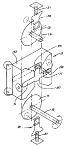
lS Figure 1 is a schematic representation of a rotary
to reciprocatory motion converter according to the
first embodiment;
Figure 2 is a side elevation of the second
embodiment;
23 Figure ~ i5 a cross-section of the second
embodiment;
Figure 4 is a series of part sectional elevations
of the carrier of the second embodiment
illustrating the movemçnt of the slider blocks;
Figure ~ is a plan of one form of shaft ~ounting of
the driven wheel of the second embodiment;
Figure 6 is a sectional view along line 6-6 of
figure 5; and
Figure 7 i5 a sectional view along li~e 7-7 of
figure 6;
Figure 8 is a sectional view along line 8-8 of
figure 6.

The first embodiment as shown at figure 1 co~prises a pair
of wheels 11 and 12 wherein one wheel 11 is driven from a


t


....... ._ .. ...


1 rotary power source through a drive shaft 13 and the other
wheel is freely rotatable on an idler shaft. Both wheels
11 and 12 are substantially co-pl~nar and are
interconnected by an endless flexible drive member 14
which is engaged with both wheels 11 and 12. The wheels 11
and 12 are associated with a housing body Inot shown in
figure 1) having a central axis which is substantially
parallel with the perpendicular axis interconnecting the
axes of rotation of the wheels 11 and 12. The housing body
slidably supports a carrier 15 which extends transversely
with respect to the central axis of the housing body and
extends to both sides of the flexible drive member 14 to
provide two parallel transversely extending side portions
15a and 15b. The opposed faces of the side portions 15a
and 15b are formed with a transversely extending track 16.
In the case of the embodiment the track takes the form of
a slot extending through the ~alls of the side portions
15a and 15b however, if desired the track may be ~ormed as
a channel in the opposed faces of the side portions. The
flexible drive member 14 ~upports at a point along its
length a slider 17 which takes the form of a fixture ~ith
a protruding shaft fixed to the drive member and extending
equally to each side of the dri~e member 14. The shaft
supports a pair of rollers one 2t each end. Each roller is
received in the slots 16 in the side portions 15a and 15b
of the carrier . The side portion 15a of the carrier ~hich
is located ~o the side ~f the w~eels 11 and 12 having the
support shafts 13 for the wheels is formed with a ga~ 20
whereby on movement of the carrîer 15 past the shaft the
side portion can pass over the shaft by the gap moving
past the shaft.


l With rotation of the drive shaft 13 the driYen whsel 11 is
caused to rotate and the idler wheel 12 is ~aused to
rotate through the presence of the flexibl~ drive member
1~. As a result of the movement of the flexible drive
member 14 the slider 17 i5 carried in the direction of
movement of the flexible drive member causing the carrier
also to be moved. On the slider reaching one of the wheels
it will be caused to move from one side c~f the wheel to
the other, with continued rotation of the whe~ls and this
transverse movement of the slider 17 is accommodated
through the ~ngagement of the rollers of the slider in the
tracks 16 in each side portion 15a and 15b ~f the carrier.
On the slider 17 reaching the other side of the wheel it
will be carried in the opposite direetion to that
previously produced to take the carrier with it.

To prevent disengagement of the slider 17 fro~ the track
16 of the one side portion 15a a pair of spaced guide
members 18 are supported adjacent to each of the wheels 11
and 12 which serve to fill the gap 20 provided in the one
~ide portion 15a ~hen the carrier is at either of its end
positions and provide a continuation of ~he track 16 in
the one side portion 15a when the carrier 1~ reaches its
endmost positions and at the point that the slider 17 is
located in the opening 20. In addition the guide members
18 are slidably supported from the housing body support
(not shown) to be capable of limited axial movement. A
biassing means 21 biasses the guide me~ber 18 to a
position slightly innermost of the end position of the
carrier whe~eby on engagement by the carrier it will be
carriecl to the end position. In adclition in the eYent of
there being some movement of the

- 6 -

l carrier beyond the end position as a result of inertial
forces the guide member 18 is able to move accordingly
with the carrier to ensure the slider is supported
substantially equally to both sides o~ the drive member
14. In this case, the in~ard spring bias temporarily
clamps the guides to the carrier and would accommodate any
axial movement of the carrier as a result of inertial
and/or gravitational forces and/or other forces in the end
regions of the travel of the carrier which may cause the
carrier to move axially away from the perimeter of the
wheel. It should be appreciated ~ha~ the biassing means 21
may take any desired form.

The second embodiment as shown at figures 2, 3 and 4
comprises a pair of wheels 111 and 112 whereby one wheel
111 is driven from a rotary power source through a drive
shaft 113 and the other wheel is freely rotatable on an
idler shaft. B~th wheels 111 a~d 112 are associated with a
housing body 119 having a central axis which is
2C substantially parallel with the axis interconnectin~ the
axes of rotation of the wheels 111 and 112. The housing
body 119 comprises a recta~gular channel section having
obliquely inwardly direct~d flanges 131 at the ~dges. A
cover plate (not shown) may be fixed to its open face i~
desired. The housing body supports a carrier 115 ~hich
extends transversely across the support and which
substantially lies to both sides of the drive member 114
to provide two parallel transversely extending side
portions 115a and 115b. The opposed faces of the ~ide
portions 115a and 115b are each formed with a track 116
which extends along both side portions and ~hich is formed
as a channel in the opposed f~ces of the side portions
115a and 115b. The drive ~ember 114 supports at a point
along its length a slider 117 which takes the Eorm o~ a
fi~cture with a protrudin~ ~hat ~ixed to the fle~cible
drive member and which extends equally over the flexible
drive member transverse thereto. The shaft supports a

- 7 - ~ Y~

l slider block 121 at each end. The slider blocks 121 are
received in the channels 116 in the side portions 115a and
115b. The one side portion 115a which is located to the
side of the wheels 111 and 112 having the shafts fixed
thereto is formed with a gap 120 transverse to the axis of
the track whereby on movement of the carrier 115 past the
shafts, the shafts are received in the gap 120. The length
of the slider blocks are sllch that on the slider block
moving along the track when the portion of the drive
member 114 engages either of the wheels 111 or 112, ancl
the slider block engages the opening in the one
transversely extending portion the portion of the slider
carrying the shaft does not enter the opening until the
leading edge of the slider is engaged with the opposite
side of the slot as shown at figures 4a, b, c and d. As a
result both sides of the shaft are constantly supported by
the tracks 116 and subjected ~o the same forces which
~ounteract any inertial forces and/or gravitational forces
and/or other forces exerted thereon. If desired guide
members similar to the guide members 18 of the first
embodiment may be provided at each end position of the
c2rrier to fill the gap 120 on the ~arrier reaching its
end position.

With rotation of the drive sh~ft 113 the wheel 111 is
caused to rotate and the idler ~heel 112 is caused ~o
rotate thro~gh the presence of the flexible drive member
llg. As a result of the movement the flexible drive member
114 the slider 117 is carried in the direction of movement
of the drive member causing the carrier also to be moved.
On the slider reaching one of the wheels 111 it will be
caused to move Erom one side of the wheel to the other
side with further rotation of the wheels and this
transverse movement of the slider 117 is accommodated
through the engagement of the slider blocks 121 of the
slidar in the tracks 116 in each side portion 115a and

- 8 - ~ 3 ~

l 115b of the carrier whereby on the slider reaching the
other side of the wheel it will be carried in the opposite
direction to that previously produced to take the carrier
with it.


The carrier 115 oE the second embodiment is supported to
facilitate its axial movement in the housing body 119 by a
set of rollers. The rollers comprise a first set of four
rollers 122 located on the outer face of the carrier
adjacent the open face of the housiny body. The rollers
are positioned at the corners of the outer face of the
carrier and are directed obliquely from the carrier to be
received against the flanges 131 provided at the open face
of the housing body innerfaces.
The second set of rollers comprise a pair of rollers 123
located to each side of the carrier and extendin~ from the
innermost face. One roller 123a is located uppermost on
the carrier while the other roller 123b is located
lowermost on the carrier. Both of the rollers
substantially engage the internal face of the housing bod~
119 .

The housing body may comprise a formed channel section
formed from mild steel ~heetin~. The rollers 122 and 123
are mounted to be adjustable in their radial movement to
accommodate dimensional tolerances of the housing. In the
event of there being any discontinuities in the dimensions
of the housing body such discontinuities are accommodated
by the resilience of the channel section. In addition such
resilience can be used to provide some preloading on the
rollers in the carrier to eliminate lateral movement of
the carrier in the housing body. If desired the housing
body may be formed as a bo~ section.
The mountin~ for the shafts of the embodiment is ~how~ at
figure 5, 6, 7 and 8. Each shaft 213 is supported in the

.
I

1 housing member 220 by a first internal bearing 224
supported within a bearing housing 225 extending from the
rear face and has a pulley wheel 227 fixed to it. The
inner end 218 of the shaft 213 has a wheel 211 fixed
thereto and is supported from the housing member by an
internal bearing 229 located in a bearing housin~ 231
located at the end of a boss 230 extending from the
internal face of the housing member 220. The boss
comprises a pair of vertically spaced portions 230a and
230b which deEine between themselves a journal space
shaped to accommodate the shaft 213. The transverse
dimension of the boss is substantially equal to the
diameter of the shaft resulting in the sides of the shaft
being exposed. The lower portion 230b of the boss is
formed as a downwardly extending gusset between the
housing member 220 and the second bearing 229. The upper
portion 230a has a profiled upper portion conforming to
the path of the most adjacent portion of the slider block
232 as it moves around the boss as shown at figure 6 with
movement of the shaft supported thereby around the wheel
211.

A suitable application of the invention relates to a pump
utilising a piston. An advantage of the embodiment resides
in the capacity to supply motion for long stroke pumps
utilising a piston.

It should be appreciated that the scope of the present
invention need not be limited to the particular scope of
the embodiment described abo~e. In particular the
invention need not be limited to a rotary to reciprocatory
motion converter but is equally applicable to a
reciprocatory to rotary motion converter. In addition the
engagement between the wheels and endless flexible member
may talce any suitable form and need not be limited to a


,~
.,. .~

- 10~ L~

1 chain and toothed wheel relationship described in relation
to the embodiment. In addition the housing body may ta~e
any suitable forlD to support the carrier in its
reciprocation between the wheels. In its support by the
housing body the carrier can be slidably supported by any
suitable means. Furthermore if desired both shafts may be
driven to provide the reciprocatory movement of the
carrier or may both be driven as a result of reciprocation
by the carrier.


Representative Drawing
A single figure which represents the drawing illustrating the invention.
Administrative Status

For a clearer understanding of the status of the application/patent presented on this page, the site Disclaimer , as well as the definitions for Patent , Administrative Status , Maintenance Fee  and Payment History  should be consulted.

Administrative Status

Title Date
Forecasted Issue Date 1992-12-08
(22) Filed 1988-06-14
(45) Issued 1992-12-08
Deemed Expired 2001-12-10

Abandonment History

There is no abandonment history.

Payment History

Fee Type Anniversary Year Due Date Amount Paid Paid Date
Application Fee $0.00 1988-06-14
Registration of a document - section 124 $0.00 1989-08-25
Maintenance Fee - Patent - Old Act 2 1994-12-08 $50.00 1994-10-28
Maintenance Fee - Patent - Old Act 3 1995-12-08 $50.00 1995-11-20
Maintenance Fee - Patent - Old Act 4 1996-12-09 $250.00 1996-12-12
Maintenance Fee - Patent - Old Act 5 1997-12-08 $75.00 1997-12-02
Maintenance Fee - Patent - Old Act 6 1998-12-08 $75.00 1999-06-29
Maintenance Fee - Patent - Old Act 7 1999-12-08 $75.00 1999-11-10
Owners on Record

Note: Records showing the ownership history in alphabetical order.

Current Owners on Record
DARTNALL ENGINEERING & INNOVATION PTY. LTD.
Past Owners on Record
DARTNALL, WILLIAM JOHN
LANGRIDGE, DAVID
Past Owners that do not appear in the "Owners on Record" listing will appear in other documentation within the application.
Documents

To view selected files, please enter reCAPTCHA code :


To view images, click a link in the Document Description column. To download the documents, select one or more checkboxes in the first column and then click the "Download Selected in PDF format (Zip Archive)" or the "Download Selected as Single PDF" button.

List of published and non-published patent-specific documents on the CPD .

If you have any difficulty accessing content, you can call the Client Service Centre at 1-866-997-1936 or send them an e-mail at CIPO Client Service Centre.


Document
Description 
Date
(yyyy-mm-dd) 
Number of pages   Size of Image (KB) 
Drawings 1993-11-08 8 202
Claims 1993-11-08 7 167
Abstract 1993-11-08 1 24
Cover Page 1993-11-08 1 15
Description 1993-11-08 9 374
Representative Drawing 2001-07-30 1 9
Correspondence 1999-01-24 2 61
Fees 1999-06-29 1 45
Fees 1997-12-02 1 44
Fees 1998-11-18 1 43
Fees 1999-11-10 1 41
Fees 1996-12-12 1 48
Fees 1995-11-20 1 42
Fees 1994-10-28 1 41