Language selection

Search

Patent 1311461 Summary

Third-party information liability

Some of the information on this Web page has been provided by external sources. The Government of Canada is not responsible for the accuracy, reliability or currency of the information supplied by external sources. Users wishing to rely upon this information should consult directly with the source of the information. Content provided by external sources is not subject to official languages, privacy and accessibility requirements.

Claims and Abstract availability

Any discrepancies in the text and image of the Claims and Abstract are due to differing posting times. Text of the Claims and Abstract are posted:

  • At the time the application is open to public inspection;
  • At the time of issue of the patent (grant).
(12) Patent: (11) CA 1311461
(21) Application Number: 593289
(54) English Title: FLOW CONTROL VALVE
(54) French Title: SOUPAPE DE REGULATION DE DEBIT
Status: Deemed expired
Bibliographic Data
(52) Canadian Patent Classification (CPC):
  • 251/15
  • 251/34
(51) International Patent Classification (IPC):
  • F16K 3/00 (2006.01)
  • F16K 3/08 (2006.01)
(72) Inventors :
  • PILOLLA, JOSEPH J. (United States of America)
  • PILOLLA, PATRICK M. (United States of America)
(73) Owners :
  • SLOAN VALVE COMPANY (United States of America)
(71) Applicants :
(74) Agent: BORDEN LADNER GERVAIS LLP
(74) Associate agent:
(45) Issued: 1992-12-15
(22) Filed Date: 1989-03-10
Availability of licence: N/A
(25) Language of filing: English

Patent Cooperation Treaty (PCT): No

(30) Application Priority Data:
Application No. Country/Territory Date
07/166,466 United States of America 1988-03-10

Abstracts

English Abstract


FLOW-CONTROL VALVE
ABSTRACT OF THE DISCLOSURE

A flow-control valve including a separable body and
fitting which define a cavity to house a seal assembly having a
rotatable seal member with flow ports and a stationary seal
member with corresponding flow ports. The rotatable seal member
is selectively positionable by means outside the body to
position the flow ports into or out of alignment to regulate or
shut-off the flow of fluid, as desired.


Claims

Note: Claims are shown in the official language in which they were submitted.


CLAIMS:
1. A flow-control valve including a body, a fluid
inlet defined in said body, said body including an elongated
cylindrical portion having a continuous cylindrical wall
defining a cylindrical chamber in communication with said
inlet, said cylindrical portion having an open end defining a
radial stop surface and said portion further defining a
radial land at an end of said continuous cylindrical wall
axially spaced from said radial stop surface, a separable
fitting threadedly engaged with said body defining a fluid
outlet, said fitting having an elongated cylindrical portion
defining a passage in communication with said fluid outlet
and said cylindrical chamber of said body, said cylindrical
portion having a radial stop surface adjacent one end thereof
in engagement with the radial stop surface of said elongated
cylindrical portion of said body, said cylindrical portion of
said fitting extending interiorly of said continuous
cylindrical wall of said body and terminating at an end
defining a radial land, said radial land defining with said
radial land of said body a seal assembly receiving cavity of
finite length, a ceramic seal assembly disposed in said
chamber between said inlet and said outlet, at least two
annular elastomeric seal members, each of which is compressed
between one of said radial lands, said ceramic seal assembly
and said continuous cylindrical wall, said seal assembly
including a stationary, ceramic seal member nonrotatably
mounted with respect to said housing, said stationary member


defining one or more flow ports therethrough, a rotatable,
ceramic seal member disposed adjacent to and in face-to-face
contact with said stationary seal member, said rotatable seal
member defining one or more ports therethrough, operator
means outside the housing connected to said rotatable seal
member operable to selectively position said ports of said
rotatable seal member into and out of alignment with said
ports of said stationary seal member.


11

2. A valve as in Claim 1 in which said operator
means includes an elongated sleeve member overlying said
cylindrical portion of said body relatively rotatable with
respect thereto and a member extending from said rotatable
seal member and connected to said sleeve member for selective
positioning of said rotatable seal member with respect to
said stationary seal member.

12


3. A valve as in Claim 1 in which said ports of said
rotatable and stationary seal members are arranged such that
relative rotation of said seal members between predetermined
points varies the size of the orifice defined by the alignment of
corresponding ports of said rotatable and stationary seal
members.
4. A valve as in Claim 1 including an elastomeric
seal member disposed between said stationary seal member and said
housing.
5. A valve as in Claim 1 including a ceramic thrust
washer disposed between said housing and said rotatable seal
member such that said rotatable seal member is compressed between
said stationary seal member on one side and said thrust washer
on said other side.
6. A valve as in Claim 1 including a removable
fitting adapted to be secured to said housing and to exert force
against said thrust washer.
7. A valve as in Claim 6 including an elastomeric
seal member disposed between said removable fitting and said
thrust washer.
8. A valve as in Claim 1 in which said inlet is
axially aligned with said outlet.

13


9. An in-line flow-control valve for controlling
the flow of fluid, said valve comprising an elongated body
defining a flow passage having an inlet, a separable fitting
secured to said body defining a flow passage in communication
with said flow passage of said body and defining an outlet;
said body including an elongated cylindrical
portion having a continuous cylindrical wall defining a
cylindrical chamber in communication with said inlet, said
cylindrical portion having an open end defining a radial stop
surface and said portion further defining a radial land at an
end of said continuous cylindrical wall axially spaced from
said radial stop surface, a separable fitting threadedly
engaged with said body defining a fluid outlet, said fitting
having an elongated cylindrical portion defining a passage in
communication with said fluid outlet and said cylindrical
chamber of said body, said cylindrical portion having a
radial stop surface adjacent one end thereof in engagement
with the radial stop surface of said elongated cylindrical
portion of said body, said cylindrical portion of said
fitting extending interiorly of said continuous cylindrical
wall of said body and terminating at an end defining a radial
land, said radial land defining with said radial land of said
body a seal assembly receiving cavity of finite length, at
least two annular elastomeric seal members, each of which is
compressed between one of said radial lands, said seal
assembly and said continuous cylindrical wall;

14

a seal assembly disposed within said cavity in
fluid tight relation;
said seal assembly comprising at least one fixed,
and one rotatable seal member having planar surfaces in
face-to-face sealing contact, each such member containing at
least one flow port which when aligned, permits flow through
said valve;
said planar surface of said rotatable member being
adapted to selectively close said at least one port of said
stationary seal member; and
operating means external to said body connected to
said rotatable seal member to effect rotation thereof.


10. An in-line flow-control valve as claimed in
Claim 9 wherein said operating means includes an elongated
sleeve rotatably received upon said elongated cylindrical
portion connected to said rotatable seal member.


16


11. An in-line flow-control valve as claimed in Claim
10 wherein said body includes an enlarged hexagonal portion
adjacent said inlet and said fitting includes an enlarged
hexagonal portion adjacent said outlet, and said sleeve is
rotatably received and retained upon said body between said
hexagonal portions.
12. An in-line flow-control valve as claimed in Claim
10 wherein said operating means includes an operator connecting
said sleeve to said rotatable seal member.
13. An in-line flow-control valve as claimed in Claim
12 wherein said cylindrical portion of said body includes a
circumferential slot extending partially therearound, said
operator includes a tab extending from said body through said
slot, and said sleeve includes a longitudinal groove which
receives said tab.
14. An in-line flow-control valve as claimed in Claim
13 wherein said rotatable seal member comprises a disc, said disc
having a peripheral relief defining spaced abutment surfaces,
said operator includes arcuate legs extending from said tab
conforming to said outer peripheral relief and having ends
engaging said abutment surfaces.


17


15. An in-line flow-control valve as claimed in Claim
10 wherein said abutment surfaces are about 180 degrees apart
upon said periphery of said rotatable member.
16. An in-line flow-control valve as claimed in Claim
14 wherein said operator comprises An integral thin band defining
said arcuate legs and said upstanding tab.
17. An in-line flow-control valve as claimed in Claim
14 wherein said circumferential slot terminates in stop surfaces
about 90 degrees apart, engagement of said tab with said stop
surfaces defining the limit of rotation of said sleeve.
18. An in-line flow-control valve as claimed in Claim
9, including means applying a predetermined pre-load upon said
planar surfaces of said seal members to urge said planar faces
into face-to-face sealing contact.
19. An in-line flow-control valve as claimed in Claim
18 including at least one O-ring in said cavity in compression
between said seal assembly and one of said radial lands.
20. An in-line flow-control valve as claimed in Claim
19 including two O-rings each one of which is in compression
between said seal assembly and one of said lands.
21. An in-line flow-control valve as claimed in Claim
20 wherein said seal assembly includes a thrust washer having a
flow passage therethrough in fluid communication with the said at
least one flow port of said rotatable seal member, said thrust
washer and said rotatable seal member including planar surfaces
in face-to-face sealing contact.

18

22. An in-line flow-control valve as claimed in Claim
21 wherein said stationary seal member and said thrust washer
each include a second planar face spaced from said planar faces
in face-to-face sealing contact with said rotatable seal member,
one of said O-rings being compressed between one of said lands
and said second planar face of said stationary member and the
other of said O-rings being compressed between said second planar
face of said thrust washer and the other of said lands.
23. An in-line flow-control valve as claimed in Claim
9 wherein said seal members comprise ceramic discs.
24. An in-line flow-control valve as claimed in Claim
22 wherein said seal members comprise ceramic discs.
25. An in-line flow-control valve fox controlling the
flow of fluid, said valve defining a flow passage having an
inlet, an outlet, and a seal assembly receiving cavity and a
circumferential slot open to said cavity;
a seal assembly disposed within said cavity in fluid
tight relation;
said seal assembly comprising at least one fixed, and
one rotatable disc having planar surfaces in face-to-face sealing
contact, each such disc containing at least one flow port which
when aligned, permits flow through said valve;
said planar surface of said rotatable disc being
adapted to selectively close said at least one port of said
stationary seal member; and
operating means external to said body connected to said

19

rotatable disc to effect rotation thereof, said operating means
including a peripheral relief defining spaced abutment surfaces
and an operator extending from said valve through said slot and
including legs engaging said abutment surfaces.
26. An in-line flow-control valve as claimed in Claim
25 wherein said body includes an elongated cylindrical portion,
and said operating means includes an elongated sleeve rotatably
received upon said elongated cylindrical portion connected to
said rotatable disc.
27. An in-line flow-control valve as claimed in Claim
26 wherein said body includes an enlarged hexagonal portion
adjacent said inlet and said fitting includes an enlarged
hexagonal portion adjacent said outlet, and said sleeve is
rotatably received and retained upon said body between said
hexagonal portions.
28. An in-line flow-control valve as claimed in Claim
25 wherein said operator includes a tab extending from said body
through said slot, and said sleeve includes a longitudinal groove
which receives said tab.
29. An in-line flow-control valve as claimed in Claim
wherein said abutment surfaces are about 180 degrees apart
upon said periphery of said rotatable member.
30. An in-line flow-control valve as claimed in Claim
28 wherein said operator comprises an integral thin band defining
said arcuate legs and said upstanding tab.
31. An in-line flow-control valve as claimed in Claim


28 wherein said circumferential slot terminates in stop surfaces
about 90 degrees apart, engagement of said tab with said stop
surfaces defining the limit of rotation of said sleeve.
32. An in-line flow-control valve as claimed in Claim
including means applying a predetermined pre-load upon said
planar surfaces of said discs to urge said planar faces into
face-to-face sealing contact.
33. An in-line flow-control valve as claimed in Claim
25 including at least one O-ring in said cavity compressed
against said seal assembly.
34. An in-line flow-control valve as claimed in Claim
33 including two O-rings each one of which is compressed against
said seal assembly.
35. An in line flow-control valve as claimed in Claim
21 wherein said seal assembly includes a thrust washer having a
flow passage therethrough in fluid communication with the said at
least one flow port of said rotatable disc, said thrust washer
and said rotatable disc including planar surfaces in face-to-face
sealing contact.
36. An in-line flow-control valve as claimed in Claim
35 wherein said stationary disc and said thrust washer each
include a second planar face spaced from said plannar faces in
face-to-face sealing contact with said rotatable disc, one of
said O-rings being compressed against said second planar face of
said stationary disc and the other of said O-rings being
compressed against said second planar face of said thrust washer.

21

37. An in-line flow control valve as claimed in Claim
36 wherein said discs are made of ceramic.
38. An in-line flow control valve as claimed in Claim
25 wherein said discs axe made of ceramic.
39. An in-line flow control valve as claimed in
Claim 34 wherein said discs are made of ceramic.


22

Description

Note: Descriptions are shown in the official language in which they were submitted.


~3~4~

FLQW-CONT~OTJ VALV~

BA~B~N~ OF THE INVENTION
The present invention relates to in-line flow-control
valves which seal against the flow of fluid through the valve.
Arrangements of this general type are shown in the prior art U.S.
Patent~ 263,330; 341,170,o 2,556,583; 2,709,566; and 2,883,150.
None of these prior art patents teaches a valve formed of a
separable body and fitting which define a cavity to house a
rotatable seal assembly operable to control fluid flow.

SUMMARY OF THE INVENTION
The present invention provides an in-line flow-control
valve incorporating a separable body and fitting which house a
rotatable seal assembly operable from outside the body to control
the flow of fluid through the valve. The assembled body and
fitting define a cavity o~ finite axial length which receives and
retains a seal assembly in fluid tight relation~ The seal
assembly is comprised of at lea~t one fixed, and one rotatable
seal member, having planar surfaces in face-to-face contact.
Each seal member contains one or more flow ports which, when
aligned, permit flow through the valve. Operating means external
to the body and connected to the rotatable seal member, effects
rotation of the rotatable member to position the ports of the
rotatable seal member either into or out of alignment with the
flow port~ of the stationary seal member.


. ~ ~ . .. .


-.. . : . .
- , . - . .
- ~ . -

~ 3 ~

In a preferred form ~he rotatable seal member includes
a peripheral relief defining spaced abutment surfaces. An
operator disposed in the periphexal relief has ends in operative
contact with the abutment surfaces and includes means extending
from the body to effect rotation of the rotatable seal member.


BRIEF ~ESCRIPTION OF THE DR~aI~
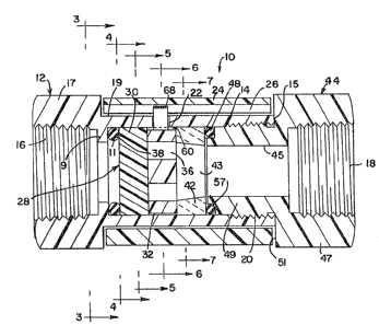
FIGURE 1 shows a side view vf the flow-control valve of
the present invention.
FIGURE 2 shows a sectional view of the flow-control
valve depicted in FIGURE 1 taken along lines 2-2.
FIGURE 3 ~hows a cross-sectional view of the flow-
control valve in FIGURE 2 taken along lines 3-3.
FIGURE 4 sh~ws a cross-sectional view of the flow-
control valve in FIGURE 2 tak~n along lines 4-4.
FIGURE 5 show~ a cross-~ectional view of the flow-
control valve in FIG~RE 2 taken along lines 5-5.
FIGURE 6 shows a cross-sectional view of the flow-
control valve in FIGURE 2 taken along lines 6-6.
FIGURE 7 shows a cross-sectlonal view of the flow-
control valve in FIGURE 2 taken along lines 7-7.


~TAILED DE~RIPTION OF T~E INVENTI~N
A flow-control valve, generally indicated by the
numeral 10, is illustrated in FIGURES l and 2. The valve 10
includes a substantially elongated, cylindrical body 12 defining


~.


~ '

~ 3 ~

a cen~ral bore 14, provided with a fluid inlet 16 at one end. An
inwardly directed radial wall 9 defines a radial land ll. The
opposite end of body 12 terminates in a radial stop surface 15.
Bore 14 includes internal threads 20 adjacent radial stop surface
15. Body 12 includes an enlarged hexagonal portion 17, adjacent
inlet 16t and the remaindex of the body defines a cylindrical
portion 19 which extends to radial stop surface 15. As best
shown in FIGURE 6, a circumferential slot 22 extends partially
about the circumfer~nce of the body 12 in the cylindrical portion
19, and i5 open to bore 14. In this embodiment, the slot extends
about 90 degrees. It terminates in stop surfaces 23.
An elongated annular sleeve member 24 open at both ends
overlies cylindrical portion 19 of body 12. The sleeve member 24
is relatively rotatable with respect to body 12. A longitudinal
groove 26 is formed in the inner cylindrical wall of the sleeve
member 24. The sleeve member 24 forms the operatiYe element of
an operating means for opening and closing the valve as will be
explained.
A fitting 44 is provided which includes a central bore
45 defining a fluid outlet 18. An enlarged hexagonal portion 47
is formed ad~acent outlet 18. An annular cylindrical portion 49
extends from the hexagonal portion 47 and includes threads which
mate with threads 20 and body 12. The hexagonal portion 47
includes radial stop surface 51 adapted to be abutted by radial
stop surface 15 when the fitting 44 is threaded onto threads 20.
Fitting 44 includes an end opposite out~et 18 which

.


~13~6~


includes a counterbore having a radial land 57. With fitting 44
affixed to threads 20 of body 12 and radial stop surface 15 in
abutting relation to radial stop surface 51, radîal land ll of
body 12 and radial land 57 of fitting 44 define a seal member
receiving chamber within the body 12 of a finite axial length.
This chamber receives and retains a seal assembly 28 in fluid
tight relation.
Seal assembly 28, disposed in the seal member
receiving chamber in the assembled body and fitting between
radial lands ll and 57, consists of three separate parts, a
stationary seal member 30 secured to the body 12 and fixed
against rotation, a rotatable seal member 32 rotatable within the
housing 12 and a thrust washer 42.
Each of the seal assembly components is a generally
cylindrical di~c which includes spaced, parallel planar radial
face~. The ad~acent faces of the non-rotatable member 30,
rotatable member 32 and thrust washer 42 are in fac~-to-face
contact. These surfaces are polished to a degree such that this
face-to-face contact seals against the flow or leakage of fluid
along these mating faces. The discs of the seal assembly are
preferably made of ceramic. It is contemplated, however, that
other materials, such as plastic, carbon graphite, or stainless
steel could be utilized for the discs.
~ second xadial face of the non-rotatable member 30
faces radial land ll of body 12. Similarly, a second radial face
of the thrust washer 42 faces radis1 land 57 of the counterbore


,, . . .
~ :.


:
.:
.

~ 3 ~

in the end of fitting 44. A seal, in the form of an elastomeric
O-ring, 38 is provided between land 11 and the adjacent face of
stationary member 30. A seal, in the form of an elastomeric O-
ring, 48 is pro~ided in the counterbore and is disposed between
the adjacent radial face of thrust washer 42 and radial land 57.
The axial distance between radial lands 11 and 57 defines the
finite axial extent of the seal member receiving chamber. Upon
attachment of fit~ing 44 to threads 20 with radial stop surface
15 of body 12 in engagement with radial stop surface 51 of
fitting 44, seals, namely O-rings 38 and 48 are placed in
compression between the seal assembly and the radial lands 11 and
57r The seals provide a fluid tight seal against the associated
radial faces of th~ seal assembly and ~he radial stop surfaces ll
and 57 and also provide a predetermined preload upon the discs to
urge the contacting faces into fluid tight contact with each
other.
Though O-ring seals are illustrated, it is contemplated
that a variety of seals could be used. Any form of packing is
considered acceptable. It is also thought that expandable
elastomeric or metallic bellows could be substituted for the O~
ring seals illustrated.
The stationary ~eal member 30 is pinned to body 12 by
pin 70 (FIGURE 5). It includes a pair of flow ports 34, as shown
in FIGURE 4. Although t~o ports 34 are illustrated, the actual
number and size of the ports may va~y depending upon the flow
conditions of the application. The rotatable seal member 32 also


~ ' '


'
- . . ~ , : .
., ' ~ ' ' ~' ~ .
: ., .. ~ -' .: ' . ' ' ' : '

~ 3 ~

has a pair of flow ports 36, as shown in FIGURE 6, which
correspond with the ports 34. Thrust washer 42 has a passage 43
which communicates with ports 36 of rotatable seal member 32.
The flow ports 36 of the rotatable seal member 32 are arranged
relative to the flow ports 34 of the stationary seal member 30
such that rotation of the rotatable seal member 32 varies the
size of the orifice defined by the alignment of the corresponding
flow ports 34 and 36 of t~e stationary seal member 30 and the
rotatable seal member 32, respectively.
Rotatable seal member or disc 32 includes a peripheral
relief 60 best seen in FIGURE 6. Relief 60 extends slightly more
than 180 degre s about the periphery of disc 32 and terminates in
spaced abutment surfaces 62. An operator 64 in the form of an
integral thin band lies within relief 60. It includes arcuate
legs 66 which conform to the outer peripheral relief 60 and which
include ends engaged with abutment surfaces 62.
An upstanding tab 68 is formed intermediate arcuate
legs 66 which, as seen in FIGURES 2 and 6, protrudes from body 12
through slot 22. Upstanding tab 68 is disposed within
longitudinal groove 26 of outer rotatable sleeve 24 to engage the
operator 64 with the sleeve 24. Rotation of the sleeve causes
the operator to travel within slot 22~ The ends of legs 66
thereby impart rotational forces to disc 32 at abutment surfaces
62. The length of legs 66 is preferably such that when tab 68 is
abutting one stop surface 23 of slot 22, the abutment surface 62
is not exposed within the slot. This insures that the operator


,
' ,,
.

~L 3 ~

64 will be securely retained within the body 12 and also insures
smooth operation of the valve.
The tab 68 and ports 36 in the rotatable seal member 32
are in axial alignment, thereby providing an index for
indicating the positi~n of the disc 32 relative to the disc 30.
Indicia 70 and 71, seen in FIGURE 1, may be used to provide an
external indication of the status of the valve.
The valve 10 may be assembled by first inserting O-ring
38, seal assembly 28 and O-ring 48 into bore 14 of body 12. Pin
70 is then installed to retain stationary disc 30. Operator 64
may then be inserted through slot 22 with legs 66 disposed in
peripheral relief 60 with the ends of the legs against abutment
surfaces 62. The operator should bs made of steel or suitahle
plastic to permit the necessary bending or springing of the legs
~6 to permit this insertion.
The valve may also be assembled by inserting O-ring 38
and disc 30 and then placing operator 64 within the bore 14.
Operator 64 is positioned with the legs ~6 against the inner
surface of bore 14 with tab 68 protruding from slot 22. Disc 32,
disc 43 and O-ring 48 may then be placed within the cavity with
the ends of leg~ 66 in operating contact with abutment surfaces
6~. .
Rotatable sleeve 24 is then slid onto cylindrical
portion 19 of body 14 with tab 68 disposed within groove 26.
Rotation of the sleeve will thus cause rotation of ope.rator 64
and rotatable disc 32.


_ . .

., .: . :
.

~ 3 ~

Fit~ing 44 is tightened onto threads 20 until radial
stop surface 15 of body 12 engages radial stop surface 51 of
fitting 44. The O-rings 38 and 48 and ceramic seal assembly 28
are compr0ssed between radial lands 11 and 57 to seal the ceramic
seal assembly within the cavity with the appropriate preload on
the ceramic discs to permit rotation of disc 32 and yet prevent
leakage across the contacting aces. Rotatable sleeve 24 is
ret~ined on cylindrical relieved portion 19 between hexagonal
ends 17 of body 12 and 47 of fîtting 44.
The operation of the valve 10 of the present invention
is as follows. When the ports 36 o the rotatable seal member 32
are positioned as .in FIGURE 2 and 6, the "closed~' position, the
flow of fluid though the valve 10 is prohibited. In this
postion, tab 68 engages one of the two stop surfaces 23 of sl~t
22. When it is desired to permit the flow of ~luid through the
valve 10, the sleeve member 24 is rotated counter-clockwise in
FIGVRE 6, until tab 68 engages the other stop surface 23. This
aligns the flow ports 36 in the rotatable seal member 3~ with the
flow ports 34 in the stationary seal member 30. The amount of
fluid permitted to flow through the ports 34, 36 can be
co~trolled by varying the degree of rotation and alignment of the
ports such that if the sleeve member 24 were rotated 30 or 60
degrees in a counter-clockwise direction, the flow of fluid would
not be as great as if the sleeve member 24 were rotated a full 90
degrees. When it is desired to stop, or decrease the flow of
fluid through the val~e 10, the sleeve member 24 is rotated


`` ~1 3 ~


clockwise toward the "closQd~' position illustrated in FIGURE 6
un~il the desired result is obtained~
The seal assembly provides a positive stop against flow
of fluid in that, when positioned in the closed position, the
planar surface of rotatable seal member 32 that is in contact
with stationary member 30, closes off flow ports 34. Furtherl
the face-to-face contact of the radial suxfaces of the rotatable
member 32, maintained by the preload of O-rings 38 and 48,
prevents entry of contaminants along the sealing faces. The
inclusion of thrust washer 42 in the seal assembly 28 isolates
the elastomeric O-ring seals from movement of the rotatable
member 32. Relative movement is limited to the planar surfaces
of the discs which are in face-to-face contact.
Thus, it has been shown that the present invention
provides an in-line flow-control valve with a seal assembly
operable from outside the housing, to regulate or prevent the
flow o~ fluid through the valve. ~arious features of the
invention have been particularly shown and described in
connection with the illustrated embodiment of the invention,
however, it must be understood that these particular arrangements
merely illustrate and the invention is to be given its fullest
interpretation within the terms of the appended claims.


Representative Drawing
A single figure which represents the drawing illustrating the invention.
Administrative Status

For a clearer understanding of the status of the application/patent presented on this page, the site Disclaimer , as well as the definitions for Patent , Administrative Status , Maintenance Fee  and Payment History  should be consulted.

Administrative Status

Title Date
Forecasted Issue Date 1992-12-15
(22) Filed 1989-03-10
(45) Issued 1992-12-15
Deemed Expired 2002-12-16

Abandonment History

There is no abandonment history.

Payment History

Fee Type Anniversary Year Due Date Amount Paid Paid Date
Application Fee $0.00 1989-03-10
Registration of a document - section 124 $0.00 1989-08-25
Maintenance Fee - Patent - Old Act 2 1994-12-15 $100.00 1994-10-06
Maintenance Fee - Patent - Old Act 3 1995-12-15 $100.00 1995-09-12
Maintenance Fee - Patent - Old Act 4 1996-12-16 $100.00 1996-11-13
Maintenance Fee - Patent - Old Act 5 1997-12-15 $150.00 1997-11-27
Maintenance Fee - Patent - Old Act 6 1998-12-15 $150.00 1998-10-13
Maintenance Fee - Patent - Old Act 7 1999-12-15 $150.00 1999-09-30
Maintenance Fee - Patent - Old Act 8 2000-12-15 $150.00 2000-10-31
Owners on Record

Note: Records showing the ownership history in alphabetical order.

Current Owners on Record
SLOAN VALVE COMPANY
Past Owners on Record
PILOLLA, JOSEPH J.
PILOLLA, PATRICK M.
Past Owners that do not appear in the "Owners on Record" listing will appear in other documentation within the application.
Documents

To view selected files, please enter reCAPTCHA code :


To view images, click a link in the Document Description column. To download the documents, select one or more checkboxes in the first column and then click the "Download Selected in PDF format (Zip Archive)" or the "Download Selected as Single PDF" button.

List of published and non-published patent-specific documents on the CPD .

If you have any difficulty accessing content, you can call the Client Service Centre at 1-866-997-1936 or send them an e-mail at CIPO Client Service Centre.


Document
Description 
Date
(yyyy-mm-dd) 
Number of pages   Size of Image (KB) 
Drawings 1993-11-08 2 77
Claims 1993-11-08 13 425
Abstract 1993-11-08 1 21
Cover Page 1993-11-08 1 18
Description 1993-11-08 9 396
Representative Drawing 2001-07-30 1 19
Fees 1996-11-13 1 47
Fees 1995-09-12 1 44
Fees 1994-10-06 1 39