Note: Descriptions are shown in the official language in which they were submitted.
~3~6~
- 1 -
~ETHOD FOR FABRICATING ARTICLES W~IICH INCLUDE HIGH SILICA
C~LASS BODIES AND ARTICLES FOR~ED THEREBY
Back~round of the Invention
1. Field of the Invention
The invention pertains generally to a method for fabricating
articles which include high silica glass bodies, e.g., high silica glass optical5 ~lbers, as well as the articles produced by the method.
2. _Art Back~round
Articles which include high silica glass bodies, i.e., glass bodies
containing at least 70 percent by weight of silica, are currently employed in
a wide variety of commercial settings. For example, optical fibers, drawn
10 from high silica glass optical fiber preforms, are currently being used in
optical communication systems. Such fibers typically include a high silica
glass core encircled by a high silica glass cladding, with the former having a
higher refractive index than the latter to achieve guiding of electromagnetic
radiation. This difference in refractive index is achieved, for example, by
15 incorporating an up dopant (a dopant which increases refractive index) into
the core, or incorporating a down dopant (a dopant which decreases
refractive index) into the cladding, or through the incorporation of both up
and down dopants. Other articles which include high silica glass bodies,
such as high silica glass lenses and prisms, are used in a wide variety of
20 optical systems, while articles such as high silica glass refractory tubing,
muffles and holders are employed in the heat treatment and processing of
semiconductors .
A number of techniques have been developed for fabricating high
silica glass bodies. In perhaps the most widely used of these techniques,
25 naturally occurring quartz crystals are initially hand sorted, and then
heated to the alpha-beta quartz transition temperature (approximately
573 degrees Centigrade (C)) to fracture the sorted crystals. The fractured
quartz is again hand sorted and then crushed, typically in a ball milling
machine. After being cleaned, e.g., acid washed, the crushed quartz is then
3û introduced into an oxy-hydrogen flame to fuse the quartz powder into a
high silica glass body.
.
lL 3 ~ ~ 6 11 ~
-- 2 -
While the above-described technique is useful, it does have a
number of disadvantages. For example, this technique is relatively
expensive because of the need to select (i.e., sort) the raw material (the
naturally occurring quartz) by hand. In addition, the raw material typically
5 contains impurities, such as iron ions and other transition metal ions, as
well as hydroxyl groups, which absorb electromagnetic radiation of
wavelengths equal, or close, to those employed in commercial optical fiber
communication systems, e.g., 1.3 micrometers (~m), and thus produce
relatively high optical loss. Moreover, the raw material often contains other
10 impurities, such as zirconia, which cause scattering and/or produce
crystalline phases, e.g., zircon, which degrade the mechanical strength of
glass fibers. Additional such scattering impurities are also introduced
during the ball milling process, while additional hydroxyl ions are
introduced by the oxy-hydrogen flame. Further, this particular glass
15 fabrication technique generally precludes the incorporation of dopants into
the resulting glass body. As a consequence, this technique is generally
viewed as being undesirable for the fabrication of certain high silica glass
bodies, including optical fiber preforms.
Techniques have been developed which avoid at least some of the
20 disadvantages, discussed above, and which thus permit the fabrication of
high silica glass bodies such as optical fiber preforms. Two such related
techniques are known as the outside vapor deposition (OVD) technique and
the vapor-phase axial deposition (VAD) technique. In both techniques,
reactive gases, such as SiC14 and 2~ are flowed into an oxy-hydrogen flame
25 where they react to form particles of silica, called soot particles, which are
thermophoretically deposited onto a glass substrate. If, for example, it is
desired to increase the refractive index of the resulting glass body by
incorporating up dopants such as GeO2 or P2O5, then the reactive gases
will typically also include GeCl4 or POCl3(which react with the 2 to form
30 the up dopants). In any event, the resulting, relatively porous soot mass is
then heated to the s;ntering temperature (typically about 1400 to about
1500 degrees C,) to form a relatively dense, high silica glass body.
As discussed, both the OVD and the VAD techniques permit the
incorporation of dopants into glass bodies, and are thus useful in the
35 fabrication of, for example, optical fiber preforms. However, the rate of
;,' '
:
~L 3 ~
deposition of soot particles in these techniques is relatively low because the
deposition rate is limited both by thermophoresis and by the relatively low
concentration of silica particles in the gas streams heated by the oxy
hydrogen torch. As a consequence, the resulting glass bodies are relatively
5 expensive.
Another technique, useful in the fabrication of optical fiber
preforms, is known as the chemical vapor deposition (CVD) technique.
Here, reactive gases, such as those discussed above, are flowed into a silica
substrate tube, and allowed to diffuse to the inner surface of the tube where
10 they react to form relatively dense silica glass. Unfortunately, the rate of
glass formation is relatively low. Further, attempts to increase the rate of
glass formation by increasing the concentrations of the reactive gases have
failed because such relatively high concentrations lead to gas phase
nucleation of silica particles, which are often swept out of the substrate
15 tube by the gas stream, rather than being deposited onto the inner surface
of the substrate tube. Moreover, attempts to increase the rate of glass
formation by increasing the flow rate of the reactive gases have been
thwarted because at these relatively high flow rates there is insufficient time
for the reactive g~ses to diffuse to the inner surface of the substrate wall (to20 react and form silica) before being swept out of the substrate tube.
Consequently,this technique is also relatively expensive.
Yet another technique useful in the fabrication of high silica
glass bodies, such a~ high silica glass optical fiber preforms, is known as the
modified chemical vapor deposi$ion (MCVD) technique. This technique
2S differs from the CVD technique in that silica particles are intentionally
nucleated in the gas phase, and thermophoretically deposited onto the inner
surface of the substrate tube. This technique is advantageous because it
yields high purity glass, and permits the ready incorporation of dopants.
However, and although the rate of glass formation is significantly higher
30 than that associated with the CVD technique, and the resulting glass bodies
are thus less expensive than those produced via the CVD technique, still
higher rates of glass formation, and still less expensive glass bodies, are
being sought.
~3~L6~
A relatively new glass-forming technique, known as the sol-gel
method, offers the possibility of fabricating relatively inexpensive high silicaglass bodies. In one variant of this technique, known as the alkoxide gel
method, a silicon-containing alkoxide, such as tetraethyl orthosilicate
5 (TEOS), is mixed with a water-containing solution. Because TEOS is
normally not miscible with water, mixing is achieved by, for example,
dissolving the TEOS in a water-soluble solvent such as ethanol, and then
adding the resulting TEOS-ethanol solution to the water-containing
solution. This mixing process results in the formation of a sol, which is then
10 poured into a mold to undergo a gelation process. (A sol, for purposes of
this disclosure, denotes a combination of liquids, dissolved solids and/or fine
particles dispersed in a liquid.) Depending upon a number of variables, the
gelation process yields either a silica-containing, porous gel body (with the
pores containing liquids such as water and ethanol), or a silica-containing
15 powder which precipitates out of solution. (A gel body, for purposes of this
disclosure, is a multiphasic body, i.e., a body which includes at least a liquidand a solid phase, formed Erom a sol via the interconnection of solid
material.) If, for example, the gelation process yields a gel body, then this
body is typically dried (to remove the liquids remaining within the pores of
20 the body) and then sintered to form a densified, silica-containing glass body.
(Regarding the alkoxide gel method see, e.g., S. Sakka, Treatise on Materials
Science and Technology, Vol. 22, Glass, III ~Academic Press, New York,
1~82).)
Significantly, the starting materials employed in the alkoxide-gel
25 method are typically of relatively high purity, and thus the resulting glass
bodies are of equally high purity (the presence of impurities being
undesirable because they lead to scattering and/or optical absorption). In
addition, index-changing dopants are incorporated into the glass bodies
either during the formation of the sol, during the gelation process, or after
30 the gel body has been dried and is still porous. Further, after the drying
procedure, water (and thus hydroxyl ions) remaining within the pores of the
dried gel bodies are readily removed by contacting the bodies with (gaseous)
chlorine. t~onsequently, the alkoxide-gel method offers many advantages
when compared with the other glass-forming techniques. However, large
35 shrinkages occur during drying,- and therefore the drying process must
.~ ,~ . . . . . .
~ 3 ~
generally be carried out at a relatively slow rate to avoid cracking the gel
bodies. Moreover, relatively large glass bodies (glass bodies having a mass of
a few hundred grams) are not readily achieved.
In a second variant of the sol-gel method, known as the colloidal
5 gel method, commercially available fumed silica, or silica powder formed via
the alkoxide-gel method, is mixed with water, and the mixture is cast,
gelled, and then dried and sintered. (Regarding the colloidal gel method
see, e.g., E. M. Rabinovich et al, Journal of the American Ceramic Society,
Vol. 66, p.6~3, 1983 and D. W. Johnson, Jr. et al, ibid, p.688.) In addition
10 to having many of the advantages of the alkoxide-gel method, the second
variant also permits the ready fabrication of relatively large glass bodies,
i.e., glass bodies having a mass of a few hundred grams. However, very large
glass bodies, i.e., bodies having a mass equal to or greater than about
1 kilogram, are not easily achieved.
High silica glass bodies have also been formed by using a plasma
torch to fuse gel-derived silica powders (in this regard see U.S. Patent
No. 3,054,431 to ~leming, Jr. et al). That is, the sol-gel method was used to
form a gel body which was dried, and then crushed, to form a silica powder.
To eliminate silica particles which were either undesirably large or
20 undesirably small, the silica powder was passed through both a 20 mesh
screen as well as a 100 mesh screen. The screened powder was then flowed,
via a carrier gas, to a bait placed in the path of the plasma flame, where the
powder was melted and fused.
While the above-described plasma torch technique is
25 advantageous, this technique involves the crushing of a dried gel body,
which permits relatively little control over the sizes of the resulting powder
particles. This lack of control is significant because each plasma torch
configuration (and, in fact, each configuration of any type of heat source)
permits the melting and fusion of silica particles having only a specific,
30 corresponding size range, i.e., particles outside this specific range are either
not incorporated into the glass body being formed or, if incorporated, yield
undesirable seeds or bubble defects in the body. As a consequence of this
relative lack of particle size control, the above-described plasma torch
technique is relatively inefficient in the use of the powder feed stock, i.e.,
35 the undesirably large or undesirably small powder particles must necessarily
-
~ 3 11 ~
- 6 --
be discarded, and thus much of the powder ;s wasted.
Thus, those engaged in the development of glass fabrication
techniques have sought techniques for formin~ glass bodies which permit
improved sizing control over, and thus relatively efficient use of, the feed-
5 stock, are relatively inexpensive, avoid the incorporation of impurities-whichcause absorption and scattering, permit the incorporation of index-changing
dopants into the glass bodies, and permit the ready fabrication of very large
glass bodies, i.e., bodies having masses equal to or greater than about
1 kilogram.
10 Summary of the Invention
The invention involves a new technique for forming high-silica
glass bodies which achieves significantly improved sizing control over, and
thus relatively efflcient use of, the feed-stock, is relatively inexpensive,
avoids the incorporation of unwanted impurities into the glass bodies while
15 permitting the incorporation of index-changing dopants into the glass
bodies, and permits the ready fabrication of very large glass bodies. In
accordance with this new technique, the sol-gel method, with all of its
inherent advantages, is used to form silica-containing gel particles which are
fused into a glass body. However, and contrary to previous such techniques,
21~ the gel particles are formed, and their sizes controlled, by mechanically, and
substantially uniformly, subdividing a sol which is capable of yielding a
substantially cohesive gel body, prior to or during gelation, to produce
discrete, wet, gel particles, essentially all of which have a desired,
substantially uniform size. Alternatively, such substantially uniformly sized
25 gel particles are produced by mechanically, and substantially uniformly,
subdividing a substantially cohesive gel body, preferably while the gel body
is still substantially wet. As a consequence, undesirably large or undesirably
small gel particles are not formed, and thus, after drying, the gel particles
are readily fused into a glass body while wasting relatively little, or nothing,30 of the feed stock.
Significantly, it has been found that mechanical subdivision of a
substantially cohesive gel body is ef~ective in producing discrete, wet,
substantially uniformly sized gel particles only if the gel body is also
substantially elastic. That is, attempts to mechanically subdivide non-
35 elastic gel bodies have resulted In these bodies undergoing plastic flow to
t 3 ~
-- 7
yield non-particulate, pasty masses. Moreover, it has been
found that not all the variants of the sol-gel method are
capable of yielding substantially elastic gel bodies. For
example, the conventional alkoxide method is useful in
producing such bodies, while in many cases the conventional
colloidal method is not.
More specifically, the invention provides a method
for fabricating an article comprising silica-containing glass,
the method comprising the steps of: forming silica-containing
gel particles; fusing said gel particles into a silica-
containing glass body; and completing the fabrication of said
article, characterized in that said forming step includes the
step of mechanically subdividing a material selected from the
group consisting of an ungelled sol, a partially gelled sol,
an ungelled sol and a gel body, a partially gelled sol and a
gel body, and a gel body, and essentially all of the gel
particles produced during said forming step are wet and are of
substantially uniform size.
,
; ~ . .
1 3 ~
- 7a -
Brief Description of the Drawings
The invention is described with reference to the accompanying
Figure which depicts, in cross-section, a plasma torch useful in the practice
of the invention.
5 Detailed Description
The invention encompasses a method for fabricating articles
which include high-silica glass bodies, as well as the resulting articles.
Included among the articles encompassed by the invention are, for example,
optical fibers, glass lenses, glass prisms, glass refractory tubing, muffles and10 holders.
As discussed, the inventive fabrication met~od involves a new
technique for forming a high silica glass body. In accordance with this
technique, the glass body is formed by fusing silica-containing gel particles
produced via the sol-gel method. Significantly, essentially all (i.e., at least
15 90 percen-t) of the initial sol, or essentially all (at least 90 percent) of the
initial gel material, produced by the sol-gel method is readily transformed,
via the inventive technique, into discrete, wet, gel particles, essentially all of
which have a desired (chosen), substantially uniform size. (For purposes of
the invention, the gel particles are wet provided their liquid content is equal
20 to or greater than about 10 percent by weight. In addition, the sizes of
these, or any, gel particles are conveniently described in terms of a
distribution function characterized by a mean particle size and a standard
deviation, a. In this regard, the uniformity of the gel particle sizes is readily
; inferrable from, for example, the ratio of the relatively large particle size at
25 +1~ from the mean size to the relatively small particle size at -1 ~ from themean size. That is, a relatively large ratio, e.g., 16 or larger, indicates thatthe gel particles are relatively nonuniform in size, while a relatively small
ratio indicates that the gel particles are relatively uniform in size. For
purposes of the invention, essentially all of the gel particles are of
30 substantially uniform size provided this ratio is less than o~ equal to about' ~ .
`:
i ~ -
~3~ 11 6~
- 8 -
15, and preferably less than or equal to about 10, and more preferably less
than or equal to about 'L.) As a consequence, little or nothing of the initial
sol or gel material is discarded prior to or during the fusion step.
In accordance with the invention, gel particles having a desired,
5 substantially uniform size are formed by mechanically and substantially
uniformly subdividing either a sol, capable of undergoing gelation to yield a
substantially cohesive gel body, prior to or during gelation, or a
substantially cohesive gel body (having the additional mechanical properties
described below). (For purposes of the invention, mechanical subdivision of
10 a sol or a gel body means that the subdivision is achieved by a process
which includes the application of an external force to the sol or gel body. In
addition, for purposes of the invention, a substantially cohesive gel body is
one which, when heated in room atmosphere to 500 degrees Centigrade for
1 hour, does not disintegrate into particles having dimensions smaller than
15 about 10 ,um. Such a substantially cohesive gel body is, in general, readily
produced using the conventional colloidal and alkoxide methods, discussed
above, as well as the vapo gel method, discussed below. However, a colloidal
sol formed by dispersing silica particles having a relatively low specific
surface area, e.g., a specific surface area less than about 5 square meters per
20 gram, into a solution containing, for example, more than about 50 percent
by weight of polymeric binder, will not yield a substantially cohesive gel
body.)
If, for example, an ungelled or partially gelled sol (capable of
yielding a substantially cohesive gel body) is to be mechanically subdivided,
25 then this is readily accomplished by, for example, flowing the sol onto the
surface of a rotating disc, to fling substantially uniformly sized droplets of
ungelled or partially gelled sol into the air, and allowing the droplets to
have flights OI sufficiently long duration to achieve complete gelation.
(While not essential, the sol is heated, or a gelation agent, such as
30 formamide or hydrofluoric acid, is preferably added to the sol to speed
gelation during the flight of the sol droplets.) The sizes of these droplets
are determined by the rotational speed of the disc and the viscosity of the
sol. That is, for a fixed viscosity, an increase in rotational speed produces a
decrease in droplet size. On the other hand, for a fixed rotational speed, an
35 increase in viscosity produces an increase in droplet size.
~ 3 ~
An alternative procedure for mechanically subdividing a sol is to
flow the sol through an orifice or a nozzle positioned at the top of a
chamber, e.g., a cylindrical chamber, to produce substantially uniformly
sized sol droplets which fall toward the bottom of the chamber under the
5 influence of gravity. During their fall, the substantially uniformly sized
droplets undergo gelation to yield wet, substantially uniformly sized gel
particles, which are collected at the bottom of the chamber. The sizes of
the sol droplets, and thus the ultimate sizes of the gel particles, are
determined by the size of the orif~lce and the flow rate of the liquid sol. For
10 example, for a fixed orii~lce size, an increase in flow rate produces a decrease
in droplet size, while for a fixed flow rate, an increase in orifice size
produces an increase in droplet size. (While not essential to this procedure,
any of a variety of conventional techniques may be used to speed gelation.
For example, the chamber may be heated, a gelation agent may be added to
15 the sol, or a gas may be tangentially injected into the chamber to impart a
spiral motion to the sol droplets, all of which enhance gelation.)
When mechanically subdividing a substantially cohesive gel
body~ the subdivision is achieved by, for example, forcing the gel body
through a screen having a substantially uniformly spaced, rectilinear grid of
20 material strands, e.g., metallic or polymeric wires. For purposes of the
invention, the useful, substantially cohesive gel bodies are those which
break via brittle fracture and, preferably, are mechanically weak, i.e., have a
breaking stress ranging from about 1x10⁴ Newtons per square meter (N/m2)
to about 5X10⁶ N/m2. Gel bodies having a breaking stress less than about
25 1x10⁴ N/m2 are undesirable because they generally lack the integrity to
undergo the mechanical subdivision process, while gel bodies having a
breaking stress greater than about 5x10⁶ N/m2, while not precluded, are
less desirable because they require a relatively great amount of force to
achieve mechanical subdivision. In this regard, it has been found that the
30 desired mechanical weakness is generally achieved immediately after
gelation, provided the gel body has a liquid content ranging from about
98 percent by weight to about 40 percent by weight. Liquid contents
greater than about 98 percent are undesirable because they lead to breaking
stresses less than about 1x10⁴ N/m2, while liquid contents less than about
35 40 percent are less dssirabls because they are diffieult to proeess and lead to
,
~3~
- 10 -
breaking stresses greater than about 5X10⁶ N/m2.
Significantly, it has been found that only substantially elastic gel
bodies are useful in the invention, i.e., are capable of being mechanically
subdivided to yield discrete, wet, substantially uniformly sized gel particles.
5 (For purposes of the invention, a body is substantially elastic if it fails via
brittle fracture and if the application, and subsequent removal, of a stress
equal to ninety percent of the breaking stress of the body results in a
corresponding, permanent strain, i.e., a strain which persis-ts for at least 2
hours, of no more than about 10 percent.) That is, attempts to force non-
10 elastic gel bodies, e.g., plastic gel bodies, through a screen have resulted inthese bodies flowing through the screen to form non-particulate, pasty
masses.
It has further been found that not all variants of the sol-gel
method are useful in producing substantially elastic gel bodies. For
15 example, the conventional alko~cide variant yields such bodies, while in
many instances the conventional colloidal variant does not. However, if a
gel body formed via the conventional colloidal variant is dried to the point
that the body's liquid content is less than about 10 percent by weight, and
wetted with water so that the body's liquid content ranges from about
20 20 percent by weight to about 80 percent by weight, then the resulting body
will be substantially elastic. Moreover, it has been found that a new variant
of the sol-gel method, called the vapo gel method, is also useful in producing
substantially elastic gel bodies. In general, this new variant involves
bubbling SiCl~, in the vapor phase, into a water bath. Further details
about this new variant are to be found in U.S. Patent No.
4,767,429 issued on August 30, 1988 to J.W. Fleming and
S.A. Pardenek.
As noted, sols (which are to -undergo mechanical subdivision), to
be useful in the invention, need only be capable of yielding substantially
30 cohesive gel bodies, i.e., either substantially cohesive, substantially elastic
gel bodies or substantially cohesive, non-elastic gel bodies. However, it has
been found that the gel particles produced by mechanically subdividing sols
which are capable of yielding non-elastic gel bodies are, in some instances,
not entirely as desirable as the gel particles produced by mechanically
35 subdividing either sols which are capable of yielding substantially elastic gel
.
''' . .
~ 3 ~
- 11 -
bodies or gel bodies which are substantially elastic. That is, the latter gel
particles (here termed substantially elastic gel particles), provided they are
equal to or smaller than about 1 centimeter in size, suffer little or no
disintegration (crumbling) during the processing, i.e., the drying and
5 sintering steps, described below. Thus, although the substantially elastic
gel particles undergo shrinkage and consolidation during this processing,
this shrinkage and consolidation is substantially uniform and therefore the
substantially elastic gel particles remain substantially uniformly sized (as
defined above). On the other hand, the gel particles derived from sols
LO which yield non-elastic gel bodies (here termed non-elastic gel particles), at
times, suffer some disintegration during processing. As a consequence, the
processed, non-elastic gel particles sometimes exhibit less particle size
uniformity than the processed, elastic gel particles.
Immediately after their formation, the substantially uniformly
15 sized gel particles (formed as described above) are wet, and should be dried
prior to undergoing fusion. ~or purposes of the invention, a gel particle is
dry provided its liquid content is less than about 10 percent by weight.
Useful drying procedures involve, for example, heating the wet gel particles
in, for example, a drying oven, at a temperature ranging from about
20 50 degrees Centigrade (C) to about 250 degrees C and for corresponding
times ranging from about 1 hour to about 100 hours. Temperatures less
than about 50 degrees C and heating times less than about 1 hour are
undesirable because they are ineffective in drying relatively large batches of
gel particles. Temperatures greater than about 2S0 degrees C and heating
25 times greater than about 100 hours are undesirable because the drying
equipment and processing times are uneconomical. Alternatively, the gel
particles are dried by being exposed to room-temperature air, for relatively
long periods of time, e.g., more than 100 hours.
During drying, the originally wet gel particles shrink as a result
30 of liquid evaporation. Depending upon the drying procedure employed, this
shrinkage (substantially uniformly) reduces the dimensions of the gel
particles by percentages ranging from 0 to about 80 percent. Thus, for
example, millimeter-sized, wet gel particles shrink to dried gel particles
having (mean) sizes which range from about 0.2 millimeters (mm) to 1 mm.
.
.
~ 3 ~
- 12-
If the dried gel particles are to be incorporated into a glass body
of optical quality, then these particles are preferably contacted with a
gaseous halogen, such as gaseous Cl2, or a gas which includes a gaseous
halogen, subsequent to drying, to remove unwanted impurities such as
5 water and/or hydroxyl ions. That is, it is believed the halogen serves to
diffuse into the interior of each gel particle, react with the unwanted
impurities to form volatile (gaseous) halogenides, e.g., HCI, which then
diffuse out of the gel particle. It is also believed that this diffusion processincludes both gaseous diffusion through the pores, and solid state diffusion
10 through the solid portions of the gel particles. In this regard, the volume of
pores in each gel particle preferably ranges from about 10 percent to about
00 percent, and more preferably ranges from about 30 percent to about 80
percent. Volumes less than about 10 percent are undesirable because this
implies that an undesirably large number of pores is closed off, which
15 reduces the diffusion rate of the halogen and of the halogenides (into and
out of the gel particle) to an undesirably low level. On the other hand,
volumes greater than about ~0 percent are undesirable because the resulting
gel particles exhibit an undesirably high degree of fragility. Concomitantly,
the pore sizes preferably range from about 2 nanometers (nm) to about
20 10 ,um, and more preferably range from about 5 nm to about 1 ~m. Pore
sizes less than about 2 nm are undesirable because this also reduces the
gaseous diffusion rate of the halogen and halogenides in the pores to an
undesirably low level. Pore sizes greater than about 10 ~m are undesirable
because they imply, for example, pore volumes greater than about 00
25 percent, which are undesirable for the reason given above, and because they
make consolidation during sintering undesirably difficult. Alternatively,
such large pore sizes often imply relatively thick, solid structures
surrounding the pores, and corresponding, undesirably long solid state
diffusion lengths in the gel particle. Moreover, the specific surface area of
30 such gel particles, which necessarily includes the surface areas of the pores,
preferably ranges from about 10 square meters per gram (m2/gm) to about
1000 m2/gm, and more preferably ranges from about 20 m2/gm to about
600 m2/gm. Specific surface areas less than about 10 m2/gm are
undesirable because they also lead to undesirably long solid state diffusion
35 lengths. Specific surface areas greater than about 1000 m2/gm are
:
.
lL 3 1! ~
13 -
undesirable because this results in undesirably slow gaseous diffusion
through the pores.
(~enerally, the sol-gel variants useful in the invention yield gel
bodies, and gel particles, which, after undergoing the above-described
5 drying procedure, have the above-described ranges of volumetric porosity,
pore sizes, and surface areas.
While not essential to the invention, the gel particles are
preferably sintered after being dried, to produce particles of glass. Sintering
is achieved, for example, by first heating the particles to temperatures
10 ranging from about S00 degrees C to about 1500 degrees C (depending upon
factors such as composition and specific surface area), and then maintaining
the particles at these temperatures for corresponding times ranging from
0 hours to about 10 hours. Sintering temperatures less than about
500 degrees C are undesirable because the resulting particles exhibit
15 undesirably low densi~lcation. Sintering temperatures and times greater
than about 1500 degrees C and 10 hours are undesirable because they lead
to a relatively high likelihood of undesirable crystallization, because the gel
particles often fuse together (which is undesirable if they are to be flowed
into the path of a fusion flame to form a glass body), and because the
20 needed equipment and processing times are uneconomical. Depending upon
the particular sintering procedure, $he dried gel particles (substantially
uniformly) shrink in linear size (to become glass particles) by percentages
typically ranging from about 10 percent to about 90 percent. Thus,
millimeter-sized, dried gel particles are reduced to glass particles having
25 (mean) sizes which typically range from about 0.1 mm to about 0.9 mm.
After having been dried (and, if desired, sintered), the gel
particles are fused to form a glass body. Fusion is achieved by heating the
gel particles to temperatures above their softening point, i.e., to a
temperature where the viscosity is less than about 107-6 poise. Any of a
30 variety of heat sources are useful for this purpose including, for example, an
oxy-hydrogen torch. Preferably, however, the heat source is a plasma torch
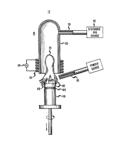
of the type described in U. S. Patent No. 3,95~1,431, discussed above. Such a
plasma torch 10 is depicted in the accompanying Figure and includes9 for
example, a cylindrical, fused silica mantle 20 which is closed at one end (the
35 top end, as viewed in the Figure). This mantle 20 is connected by a tube 30
.
~ 3 ~
- 14 -
to a source of gas 40. The torch 10 also includes a coil 50 encircling the
open end (the bottom end, as viewed in the Figure) of the mantle 20, which
coil is electrically connected to a high-powered (1~100 kilowatts) r-f
generator 60.
In the operation of the plasma torch 10, a gas, e.g., oxygen, is
flowed into the silica mantle 20 via the tube 30, and r-f power supplied to
the coil 5û, to achieve a plasma discharge which yields an incandescent
flame 70.
When the plasma torch 10 is used for fusion, the flame 70 serves
10 to produce a flow of hot gases toward, and around, a bait (a substrate upon
which a glass body is formed) 100 supported by a pedestal 110, placed in the
path of the hot gases. In addition, a carrier gas, such as nitrogen,
emanating from a feed tube 80, is initially used to flow the gel particles
through the hot gases, toward the bait. During the flight of the gel
15 particles, heat transfer from the hot gases to the gel particles serves to melt
the gel particles which, upon impacting the bait, initiate the formation of a
glass boule ~0. Subsequent gel particles are then directed through the hot
gases toward the molten portion ~5 of the boule ~0. In this regard, the
pedestal 110 is preferably lowered at a rate sufficient to keep the posi-tion of20 the molten portion ~5 constant relative to the flame 70 and feed tube 80.
Not all sizes of gel particles are melted and fused by the plasma
torch 10. That is, relatively small gel particles are entrained by the hot
gases produced by the flame 70 and, as a consequence, are flowed around
the forming boule ~0 rather than impacting, and being incorporated into,
25 the boule. By contrast, relatively large gel particles have suff~lcient
momentum to penetrate the hot gases (without being entrained), to impinge
the boule ~0. However, if the gel particles are too large, then the heat
transfer from the hot gases during the flight time of the gel particles to the
boule ~0 will be insufficient to completely soften these gel particles. As a
30 consequence, these partially softened gel particles, upon impacting the
boule, will form undesirable seeds or bubble defects in the boule.
The appropriate sizes of the gel particles that are fused by a
particular plasma torch configuration depends upon a number of plasma,
fluid flow and heat transfer parameters and must generally be determined
35 empirically. One useful empiriral procedure i9 tc~ successively flow gel
~ 3 ~
particles of different, but known, sizes into the path of the flame 70. Those
particles which are relatively small will be entrained by the hot gases, and
thus will not form a glass boule. Those particles which are too large to be
completely softened will form seeds or bubble defects.
In one embodiment of the plasma torch 10, the fused silica
mantle 20 has an inside diameter of 5 centimeters (cm). A plasma is created
within the mantle 20 by successively flowing two different gases into the
mantle via the tube 30, and applying an AC~ signal of, for example, 3
megahertz and 18 kilowatts, to the coil 50. The gas in which the plasma
10 discharge is initially struck is argon, which is flowed into the mantle 20 via
the tube 30 at a flow rate of, for example, 12 liters per minute. Th;s plasma
is then maintained in oxygen, which is flowed into the mantle 20 via the
tube 30 at a flow rate of, for example, 20 liters per minute. The resulting
pressure of the gas within the mantle 20 is atmospheric pressure, or slightly
15 higher.
The bait 100 is positioned along the axis of the cylindrical
mantle 20, at a distance of 5 cm below the open end of the mantle. The
feed tube 80 is inclined at an angle of about 75 degrees from the axis of the
mantle 20, with the open end of the tube being positioned a distance of
20 about 3 cm from the axis and a distance of 0.1 cm below the open end of
the mantle 20.
If the carrier gas used to deliver the gel particles is nitrogen, and
the flow rate is 1 liter per minute, then under the above circumstances it
has been found that the sizes of the dried (or sintered) gel particles
25 preferably range from about 0.1 mm to about 1 mm (as determined using
the above empirical procedure). That is, dried (or sintered) gel particles
having sizes outside this range are undesirable because an undesirably large
number of such gel particles are either not incorporated into the glass boule,
or form seeds or bubble defects in the boule. In this connection, the
30 inventive technique for producing substantially uniformly sized, wet gel
particles is well suited to producing gel particles which, after drying, or
drying and sintering, fall within the above size range.
After the formation of the silica boule, as described above, the
desired article is completed by a series of conventional steps. For example,
35 if an optical flber is to be formed, then the inventive technique, or some
~3~L~61~
- 16 -
other technique, is initially used to form a silica-containing rod, and then
the inventive technique is used to form a silica-containing jacket contacting,
and encircling, the rod. (In this regard, the rod would be oriented
transversely to the flame 70, and would be rotated, and moved horizontally,
5 while forming the jacket.) The rod and jacket are then drawn into an
optical ~lber using well-known techniques.
Example 1
A sol was prepared by mixing 3 batches of material in a 4 liter
blender, each batch containing 400 grams of fumed silica and 1600 grams of
10 distilled water. The fumed silica, which is sold under the trade name Cab-
O-Sil, was purchased from the Cabot Corporation of Tuscola, Illinois. The
specific surface area of the fumed silica was 200 m2/gm. The resulting sol
was allowed to stand, in room atmosphere, at room temperature, for one
hour, while gelation occurred.
The gel body produced via the above (colloidal gel) procedure
was then pushed, by hand, through an 18 mesh screen, in an attempt to
mechanically subdivide the gel body, and thus form gel particles. This
attempt failed because the subdivision process resulted in the body flowing
through the screen to form what appeared to be a sol, which then gelled to
20 form a gel body.
Example 2
A gel body formed by mixing fumed silica and distilled water, as
in Example 1, was dried in an oven at 150 degrees C for 2~ hours. During
this drying procedure, the gel body broke into centimeter-sized gel pieces,
25 each of which contained less than 5 percent by weight of water. The
volume porosity of the dried gel pieces was found to be approximately
75 percent, using conventional mercury porosimetry.
The dried gel pieces were placed in a bath of distilled water for
about 5 minutes, the excess water was decanted, and the rewetted gel pieces
30 were removed from the bath. Each of these pieces was then pushed, by
hand, through an 18 mesh screen to form substantially uniform, millimeter-
sized gel particles. These gel particles were then dried in a conventional,
glass vacuum drier, at 150 degrees C, for four hours.
* TRADEM~R~
~` !
~ 3 ~
- 17 -
The dried gel particles were placed in a furnace, and the furnace
temperature was increased at a rate of 200 degrees C per hour until the
sintering temperature of 1'~00 degrees C was reached. The gel particles were
then continuously heated at 1400 degrees C for two hours. The furnace was
5 then cooled to room temperature (about 23 degrees C), and the sintered gel
particles were removed.
The sintered gel particles were placed in a vibratory powder
feeder and flowed via a nitrogen carrier gas into the path of the flame of the
plasma torch embodiment, described above. The gas used in the plasma
10 torch was initially argon, which was flowed into the silica mantle at a flow
rate of 12 liters per minute, and then oxygen, which was flowed into the
silica mantle at a flow rate of 20 liters per minute, while a 3 megahertz,
18 kilowatt signal was applied to the coil encircling the mantle. The flow
rate of the nitrogen carrier gas was 1 liter per mi~ute, which produced a
15 flow of gel particles of approximately 10 grams per minute. The llow of gel
particles was continued for 100 minutes until a 1 kilogram-sized glass body
had formed on the bait.
Example 3
~ sol was formed by initially mixing 4.46 liters of TEOS with
20 4.46 liters of ethanol, which TEOS-ethanol solution was then mixed with
1.44 liters of slightly acidic water, to produce a solution having a pH of 3.
The resulting sol was then heated to 80 degrees C for approximately
5 minutes to achieve complete gelation.
The gel body produced via the above (alkoxide gel) procedure
25 was pushed, by hand, through an 18 mesh screen to form substantially
uniform, millimeter-sized gel particles. These gel particles were dried in a
microwave oven, using a power of 1800 watts, for 30 minutes. The dried gel
particles were then placed in an oven into which helium was flowed at a
flow rate of 1 liter per minute, while the temperature of the oven was raised
30 from room temperature to 800 degrees C over a period of 2 hours. While
maintaining a temperature of 800 degrees C, chlorine gas was also flowed
into the oven at 100 cubic centimeters per minute, for a period of one hour.
After this one hour period o~ time, the chlorine flow (but not the helium
flow) was stopped, and the oven temperature was increased to
~3~ 16~
- 18 -
1400 degrees C over a period of one hour. This temperature and
atmosphere was maintained for one hour to achieve sintering. The oven was
then cooled to room temperature, and the sintered gel particles removed.
The sintered gel particles were then flowed via a nitrogen carrier
5 gas, as described above, into the path of the flame of the plasma torch, to
form a 1 kilogram-sized glass body.
Example 4
A 30 liter glass flask was filled with 25 liters of distilled water,
into which vaporous silicon tetrachloride was flowed (at a flow rate
10 corresponding to 150 grams of silicon dioxide per minute), while the water
was sSirred. The flow of silicon tetrachloride was continued for
approximately 15 minutes, during which time the resulting sol gelled. The
flask containing the gel body was then placed in a vacuum chamber, the
pressure was lowered to 5 kilopascals, and the flask was heated to
15 150 degrees C for 8 hours to achieve drying.
After the gel body was dried to a volume of 5 liters, the gel body
was removed from the flask and pushed, by hand, through an 18 mesh
screen to form substantially uniform, millimeter-sized gel particles. These
gel particles were then placed in an oven, and the oven temperature was
20 increased to 1350 degrees C, at a rate of 200 degrees C per hour, to achieve
sintering. The resulting, sintered gel particles were then rapidly cooled to
room temperature, and removed from the oven.
The sintered gel particles were flowed via a nitrogen carrier gas,
as described above, into the path of the flame of the plasma torch, to form a
25 1 kilogram-sized glass body.
.
, ., ~ ~ .-,.: .,,
.
~,:
-
. ~ ;" ,
-.