Note: Descriptions are shown in the official language in which they were submitted.
`131 1640
L~OUID TREATMENT DE AND LIOUID EXTRACTION
ON A PAP~R PULP
BACKGROUND AND SUMM~RY OF ~R INVENTION
-. .
Durlng the production of paper from celluloslc
fibrou~ matorial pulp, it i8 typically nece~sary to
add specific chemicals to the pulp for performing
Yarlous operations, or to wash out the chemica?s
from the pulp. The addition of chemicals may be
effected by displacement flow through the pulp mass,
and wa3~iny i8 typically performed by one or more
sequences o di~placement of wa~h liquid through the
pulp mass followed by pressing of the wash liquid
from the ma~.
Conventional wa~h presses typically require
dilute pulp supplied in the consistency range of
about 2 to 5%. The dilution allows the pulp to
spread evenly onto the wash press filter media to
form a web or mat. The filter media i~
conventionally a perorated rotating drum or moving
belt. The pulp i8 thickened on the filter media to
about 10-16% consistency usually by application of
pressure to the ~at or by vacuum draw. After
thickening, washing-of the chemicals from the pulp
mat is accomplished by forcing wash water through
the ma~ (displacement) using hydraulic pressure or
drawing wa~h~water through with a vac~m. Finally,
the mat is compres~ed by the wash press to high
: ~ con5i~tency o 30 to SO% to achieve a ~igh totaI
washing efficiency. The conventional method of: . : ~30;: :compre~sing the mat for pres~ing i8 to pas~ it
through the nip of rollers or pre~s on it with a
:
,
2 1~1'1640
!
belt moving the 8ame speed as the mat.
According to the present invention, many
difficulties and inconvenience~ a~sociated wi~h ~he
prior art wash presses may be eliminated while ~till
provid~n~ effective treatment of the pulp. The
lnvention can be used not only for wa3hing of the
pulp with a final step o~ pressing, but al80 for
chemical treatment of the pulp. The invention
effects the desired re ults in a simple matmer and
with a minimum of moving parts. According to the
in~ention it is possible to supply pulp at a
consistency range of about 2-16%, and preferably
about 8 to 12% ~that is medium co~sistency pulp~
which eliminates the need for thickening at the
inlet, which i~ turn minimizes screen (filter)
) area The device according to the i~vention can
compress the pulp without the need of a nip, roll,
or moving belt, and can eliminate the need to back
wash the filter media for cleaning due to ibers
stuck in the filter media. In conventional wash
presses the mat moves at the same speed as the press
~ roller belt so that the fibers ~re pressed firmly
; against the filter media and some fiber~ staple into
the perforations of the filter media. According to
2s the invention, however, during pressing, compressed
pulp drags fiber~ from screen perforations,
producing a ~elf-cleaning effect.
According to one aspect of the present
~ invention, a device is provided for liguid treatment
of a 8U pension of cellulosic fibrous material
; (paper pulp) comprising the following elements: (a)
~- A housing having an outer, essentially solid, wall;
~ lncluding a reatricting adjustable portion. (b)
:: :
,~ :: ;.
.
;
- ' - '
. ~
.
3 t31 1640
Means defining a channel having a root wall and a
pair of ~ide walls with an open face opposite the
root wall, the channel being positioned so that the
open face thereof is adjacent the housing outer
wall, and at least one of the walls is perforated.
(c) Means for moving the root wall, and at least one
of the side walls, with respect to the outer wall in
the dimension of elongation of the channel. (d3
Means or feeding material to be treated into the
channel at one portion of the housing. (e) An
outlet for passage of treated material out of the
channel and the housing adjacent the restricting
adjustable portion of the housing outer wall. (f)
Means for introducing treatment fluid into the
channel, between the means (d) and (e), through the
housing outer wall, so that the treatment fluid
passes through the material to treat it, and out
perforations in at least one of the channel walls.
And, (g~ means for providing discharge of liquid
from the housing that has passed through
perforations in at least one of the channel walls.
The device according to the present invention
operates on the same basic principle as the press
illustrat~d and described in U.S. patent 4,534,868,
as evidenced by the commercial product sold by
Kamyr, Inc. of Glens Falls, New York under the
trademark i'Ring"~. During pressing, the channel
perforated walls move faster than the compressed
pulp and conseguently the fibers do not staple into
the perforations. Instead the compressed pulp drags
fibers from the~perforations producing a
elf-cleaning effect.
:
: ~ : : :
: -
~ ~ -
:
4 ~ 6 4 0
The mean~ for introducing treatment liquid into
the channel compri6es a hollow di~tributor extending
from the outer wall into the approximate center of
the channel between the slde walls, and compri~es a
pair Q~ p,erforated sida walls. The side walls are
parallel to the channel side walls) both of which
are preferably perforated while the root wall i8
not. The end wall of the di~tributor i8 closely
~p~ced from the root wall and al~o i8 perforated.
The housing outer wall is preferably arcuate, and
the root wall i~ an arcuate wall of a rotor with the
side walls extending radially outwardly therefrom,
and a plurality of the distributors are provided
along the housing outer wall circumferentially
spaced from each other in the direction of movement
of the channel.
The invention also relates to a method for
treating a pulp suspension using an arcuate root
wall rotatable about an axis and defining an open
channel with a pair of side walls extending radially
outwardly with respect to the root wall. At least
one of the side walls i~ rotatable with the root
wall and at least one of the channel defining walls
i8 perforated. The method comprises the steps o~
continuously and progressively: (a) Rotating the
root wall about an axis. (b) Introducing a
suspension o cellulosic fibrous material at a
consistency of about 2-16% by weight (preferably
~ about 8-12~) into the channel. ~c) Introducing
treatment fluid into the suspension in a center
portion of the channel so that the treatment fluid
permeates the ~uspension. (d~ Effecting removal of
liguid from the channel through the perforated walls
::
.
.~
.
~,' .
- . . - , ~ ,
131 1640
defining the channel to facilitate treatment and
thickening of the su6pension. And, (e) discharging
suspension having a con istency greater than that of
the introduced suspension (e.g. about 30-50%). Step
(c) i~ ~r~ferably practiced by introducing treatment
liquid in distributor~ extending into the channel
from the open part thereof oppo3ite the root wall 80
that the treatment liquid flow~ substantially
uniformly into the ~uspension at ali portions along
the radial extent thereof. The treatment liguid
preferably compri~es a wash liquid, but may also be
any of a wide variety of treatment chemicals
depending upon the particular end use of the pulp.
It is the primary object of the present
invention to provide for the simple yet effective
) chemical treatment and/or washing of pulp. Thi~ and
other objects of the invention will become clear
from an inspection of the detailed description of
the invention and from the appended claims.
BRIEF DESCRIPTION OF T~E DRAWINGS
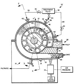
FIGURE 1 is a end diagrammatic view partly ih
cross-section and partly in elevation of an
exemplary device according to the invention;
FIGURE 2 is a side Yiew of the device of FIGU~E
1 with portions thereo shown in cross-section but
the majority shown in eIevation;
FIGURE 3 is a cross-sectional detail view of
the channel with treatment fluid introduction mean~
:
:: :
131 1640
of the device of FIGURES 1 and 2, the section taken
along 11nes 3-3 of FIGURE 1;
FIGURE 4 18 a detail view o a portion of the
channe~-defining elements of FIGURE 3 taken along
line.~ 4-4 thereof; and
FIGURE S is a cross-sectional detail view of
two channel~ in the extraction arc portivn of the
device of FIGURES 1 and 2.
DETAILED DESCRIPTION OF T~E DRAWINGS
A device for the liquid treatment of a
lS suspension of cellulosic fibrous material i8
) illustrated generally by reference numeral 10 in
FIGURES 1 and 2. The device includes a housing 11,
with an outer essentially solid wall 12, and a
restricting adjustable portion 13. The portion 13
is pivoted about point 14 and is operated by a
pneumatic cylinder 15. The a~justable portion 13
~ restricts the pulp at the discharge portion of the
; housing between it and a doctor blade 16.
The device 10 also comprises means for defining
a channel 18 having a root wall 19 and a pair o
side walls 20, with an open face opposite the root
~ wall 19, as clearly seen in EIGURES 2 and 3. The
:~ ~ channel 18 is positioned so that the open face ?
~hereof is adjacent the housing outer wall. At
least one of the walls 19, 20 is perforated.
i: Preferably both of the side walls 21 are rigid
plates with openings 22 (e.g. circular holes or
slot6) formed therein, and on the interior portion
.
: : :
:; ,
,
7 131 ~ O
of the wall 20 a liner screen 23 with small conical
holes for good filtration ~ provided. The root
wall 19 pre~erably i8 not perforated. Note the
radial grooves 24 provided in the side wall~ 20,
too, a~~i~lu3trated $n FIGURE 4.
The device lO also comprises means for moving
the root wall 19, and at least one of the side wall~
20 ~and preferably -- as illustrated in the drawings
-- both o~ the side walls 20) with respect to the
outer wall 12 in the dimension of elongation of the
channel 18. While the device 10 may be constructed
as a linear device ~e.g. see FIGURES 1 and 3 of U.S.
patent 4,534,868~, preferably it is a rotary device,
and to this end the means for moving the root wall
19 comprises a rotor including an inner tubular
) portion 25 having radially extending ribs 26 (see
FIGURES 1 and ~) emanating outwardly therefrom, the
ribs 26 being connected to the root wall 19 and
through it to the side walls 20. The inner tube 25
is keyed to a shaft 27 mounted by bearings 28 for
rotation about a generally horizontal axis, powered
by the motor 29. The motor 29 will rotate the shaft
27, tube 25, with its associated root wall, etc.,
counter-clockwise as viewed in FIGURE 1.
; 25 A plurality of channels 18 can be supported by
; the rotor 25, 26; for example FIGURES 2 and 5
illustrate an embodiment in which two channels 18
are supported the rotor 2S, 26. Note that
conventional seals (e.g. bridging ela~tomeric or
metal sealing material) 30 (see FIGURES 2 and 5 in
: particular) may be provided between the housing wall
12 and each of the side plates 20, but preferably
open grooves (see FIGURF 3) are provided which are
:
. . .
8 ~ 1 6 ~ 0
f~lled with pulp fiber~ which form a seal.
The device lO al80 comprise~ means for feeding
pulp to be treated into the channel 18 at one
portion o~ the housing 11. Such means -- in the
exempl~ry.embodiment illustrated -- includes the
inlet connector 32, which is defined in part by the
doctor 16, and the splitter segment 33. The
splitter 33 may have a knife like edge f~cing ~he
inlet 32 to reduce turbulencc and to aid in equal
division o~ the incoming pulp on ei~her side thereof
into the channel 18. An inlet 32 i~ provided for
each channel 18.
The device lO also comprises an outlet 35 (see
FIGURE 1) for passage of treated pulp out of the
channel 18 and the housiny 11 adjacent the
) restricting adjustable portion 13 of the outer wall
12. The outlet 35 is defined at the top and bottom
thereof by the adjustable portion 13 and the doctor
blade 16. The doctor blade 16 has approximately the
~ame width as the interior of the channel.
What has heretofore been described (except for
the splitter segment 33~ is present in a commercial
press sold by Kamyr~ Inc. of Glens Falls, New York ?
under the trademark "Ring"~. According to the
present invention, however -- unlike in the Ring~
press -- it is possible to treat pulp with treatment
fluid within the device lO, and to this end means
for introducing treatment fluid into the channel 18,
between the inlet 32 and the outlet 35, are
30 ~ ~provided. Thi~ means for introducing treatment
1uid m~y introduce treatment chemicals, but
preferably introduces wash liquid which will be
displaced through the pulp.
'
..
. .
9 131 1640
The mean~ for introducing treatment fluid i~
illustrated generally by reference numeral 37 in
FIGURE 1, and include~ the source or sources o
treatment fluid 38, connected by conduits 39 with
valves.40~therein to inlet nozzles 42. The nozzles
42 introduce the treatment fluid through the outer
wall 12 of the hou~ing 11 at variously positioned
arcuate spacings therealong. For example as
lllustrated in FIGURE 1, three inlet nozzles 42 are
provided the first disposed immediately ad~acent the
inlet 32, and the others spaced about 30-60 along
the circumference of the housing 12. The area in
which the nozzles 42 are disposed is referred to as
the "treatment arc" of the device 10.
The treatment fluid introducing means 37
) portions withîn the housing 11 are illustrated more
clearly in FIGURES 2 and 3, and include a hollow
distributor 43, having a hollow interior 44,
extending from the wall 12 into the approximate
center of the channel 18 between the side walls 20
: of the channel 18. The distributor 43 preferably
includes a perforated (screened) bottom wall 45
which is adjacent, but spaced from, the root wall
19, and perforated or screened side walls 46, so -
that the treatment fluid is uniformly introduced
into the pulp mass within the channel 18, as
illustrated ~y the arrows in FIGURE 3. To allow the
introduction of different types of treatment fluid
: at various portions alcng the direction of
elongation of the channel 18, solid radially
extending dividing walls 47 (see FIGURES 1 and 3)
may be provided to divide the area between the side
: walls 46 into three different compartments, one
~,
.
. ' ~ ,; " :
'
' .
lo 1 3 ~
)
associated with each nozzle 42. ~ny number of
components may be provided. The distributor 43
typically has an arcuate extent of about 80-180
(e.g. about 120).
S Pinally, the device 10 includes means for
providing discharge of liguid that has been pressed
from the pulp from the housing 11 -- i.e. liguid
that has passed through ~he side walls 20 of ~he
channel 18. The liquid dlscharge means preferably
comprises a plurality o~ filtrate outlets 48, seen
in FIGURES 1, 2, and 5. The withdrawn filtrate
moves in a circumferential flow path past the ribs
26, and through the closest outlet 48.
Operation
In operation of the device 10, pulp is pumped
or conveyed by a screw or the like at a consistency
range of about 2-16% by weight, and preferably about
: 8-12% (i.e. medium consistency) into the inlet
~ connector 32. In the embodiment illustrated in the
: 20 drawings, two inlet connectors 32 will be provided,
one for each channel 18. The pulp is split int~ two
flow paths by the splitter segment 33, one section
of pulp flowing on each side of the distributor 43
(see FIGURE 3).
As ~he rotor 25, 26 rotates, the root wall 19,
and side walls 20, defining the channel 18, rotate
counter-clockwise (FIGURE 1), and ~he pulp rotat~s
~ : with the channel 18. The treatment liquid, such as
: wash liquid, is introduced from source 38 through
~30 conduits 39 into nozzles 42, to flow into the hollow
~: ~ interior o~ the distributor 43, and passes through
` the perorations in the side walls 46 and end wall
*5 to uniformly treat the pulp. The pressure within
~,
. .
: : ,
:........ .
, ~ ~
.
- ., . , . ~ . . ', :
11 131 16~0
the diRtributor 43 i8 higher than the pressure
within the pulp in the channel 18, and the pressure
in the pulp in channel 18 i8 higher than the
pressure in the housing 11. The pressure in the
housin~ may be superatmospheric or
sub-atmospheric, but preerably is atmospheric.
Since a pressure drop occurs in the direction toward
the chan~el slde walls 20, the pulp will tend to be
held again~t the channel side walls 20 and mova with
the rotating channel 18. Liguid that i 8 displaced
from the pulp exits the channel through the liner
Rcreens 23 and openings 22 in the side walls, and
ultimately flows past the rotor ribs 26 and then
circumferentially around the rotor 25, 26 to the
filtrate outlets 48. A different treatment fluid
) may be associated with each nozzle 42, or the same
treatment 1uid can be introduced into each nozzle
42.
Chemical treatment or washing of the pulp
occurs through a treatment arc of the housing 11,
that is until a particular portion of the pulp being
carried by the rotating channel 18 reaches the end
of the distributor 43 (approximately 120 from the
inlet 32 in the embodiment illustrated in FIGURE
1). At that portion the pulp then enters what is
referred to as the "extraction arc" of the device
10~ In this arcuate portion, which extends from the
end of the distributor 43 to the outlet 35, a void
occurs immediately after the end of the distributor
43, and the channel 18 move~ faster than the pulp.
This speed differential occurs because the
: restriction formed by the movable wall 13 retards
.
: the movement of the pulp, and as a result the pulp
., :
:
,
1~
131 1640
i~ compacted and all the void space~ therein are
clo~ed up. The compaction iæ provided by the action
of friction of the channel walls 20, 19 against the
pulp, and the compaction becomes progressively
S greate~_from the di~tributor 43 tG ~he outlet 35.
The compaction cau~es the fiber~ of the pulp to be
tightly compressed against each other leaving a
minimum amount of space for liquid, and the liguid
~hat i8 compressed out of the pulp moves through ~he
channel side walls 20 to ultimately pas~ oUt the
filtrate outlets 48.
The ~ntensity of the compression is controlled
by actuation of the pneumatic cylinder 15, which
controls the position of the wall 13 with respect to
the doctor blade 16. The pressure applied by the
pneumatic cylinder 15 can be adjusted to provide
outlet cake consistencies ranging from about 30-S0
by weight, typically about 40%. ~ccording to the
invention, during pressing, since the channel walls
20 move faster than the compressed pulp, the fibers
do not staple into the perforations in the walls 20
and in~tead the compressed pulp drags the fibers
from the perforations producing a self-cleaning
affect. Ultimately, the pulp passes to the doctor
blade 16. The doctor blade 16, in addition to
forming one wall of each of the inlet 32 and outlet
35, serves to straighten the compressed pulp and
cause it to peel away from the root wall 19, and the
side walls 20. The discharged cake is then acted on
further in any conventional manner desired.
It will thus be seen that according to the
; present invention:a method and apparatus have been
provided for the æimple yet ef ecti~e treatment of
;:
~ .
:
. , .
- - .
.
'. :
. 13
~ 1 ~1 1640
cellulosic fibrous material suspensions that
overcomes many of the pro~lem~ assoc~ated with prlor
art procedure~ and apparatus. While the invention
has been herein ~hown and described in what i~
pre~ent y.concelved to be the most practical and
preferred embodiment thereof it will be apparent to
those of ordinary 8~ill in ~he art that many
modification~ may be made thereof within ~he BCOpe
of ~he invention, w~ich scope i8 to be accorded ~he
broadest interpretation of the appended claims so a~
to encompass all equivalent ~tructures and
procedures.
,~
: