Note: Descriptions are shown in the official language in which they were submitted.
131 173~
VDI 101-246
-- 1 --
REEL BAR LOADING MECHANISM WITH OUTWARDLY
PIVOTING GUID~E RAILS
Field of the In~ention
The present invention relates to a reel
loading device adapted to feed reels from upper
supporting racks or rails onto transfer arms which move
and support the reel in winding position in a paper
making machine.
Background of the Invention
A variety of different reel lowering devices
for transferring a reel from a supporting rack for
storing empty reel bars into a transfer means to move
the reel bars into a winding position have been
proposed and many such devices are currently in use.
For example U.S. Patent 1,949,997 issued March 6, 1934
to Fourness describes a paper winder wherein empty
cores are carried;from a lower rack via a pair of arms
and moved into winding position against a winding drum
to form a roll of paper. The shaft of the paper core
is transferred from~grooves or slots in the arms
transferring the core to the winding position into
co-operating slots formed in a second pair of transfer
arms that carry a finished or wound roll of paper into
a second storage rack located above the storage rack
for empty reels. This devi¢e pro~ides for the loading
~:
. ,,
,: - ' ~',
~ 3 I t 734 VDI 101-246
and unloading of reels and wound paper rolls
respectively from a winding position but is a
relatively expensive and cumbersome piece of equipment.
U.S. Patent 2~508,566 issued May 23, 1950 to
Dunton describes a web roll backstand and provides for
a transfer of a wound roll to an unwind station and
removal of the cores. A pair of arms are used to make
the transfer into the unreeling position and a second
pair of arms are used to transfer the empty reel or
core to a second storage posit:ion. Although this
device is not a device for transferring empty re~ls
into a transfer arm it does show the use of spaced arms
to make the transfer of the roll into an operating
position.
U.S. Patent 2,989,262 issued June 20, 1961 to
Hornbostel teaches the use of gravity to roll a
plurality of empty cores and apply the cores one at a
time from an inclined storage device into a loading
position where they are picked up by a transfer arm and
moved into winding position between a pair of winding
drums. The mechanism for controlling the flow of empty
cores down the relatively steep incline of the storage
device leads to significant complications in this
structure of the winder.
Yet another example of a reel loader is shown
in U.S. 3,586,253 issued June 22, 1971 to &ilbank et
al. In this device empty reels are loaded onto an
upper rack formed by a pair of rails having an abutment
stop at their lower ends so the empty reels move down
the rails to the abutment stop~ A pair of lifting and
lowering arms are provided which lifts each empty reel
over the abutment and permits it to roll to the
opposite side thereof and then lowers the reel into the
reel transfer device. The operation of the reel
lowering arms in the arrangement requires lifting the
'
'
~ ~ ~ F ~VDI 101-246
- 3
reel over the abutment, transverse movement to direct
the reel to the opposite side of the abutment and then
lowering of the reel into the transfer device. The
opposite side of the abutment in this case operates as
a cam to hold the reel in position during the initial
phases of lowering of the lowexing arms so that there
is a controlled movement of the reel along the lowering
arms. Obviously the reciprocal motion of the arm
during loading complicates the operation o~ the
lowering arms in that they first must mo~e upward to
lift the reel bars above the abutment and then downward
after the reel bars have moved along the arm to the
opposite side of the abutment into a transfer
position. U.S. Patent 4,179,329 issued
December 18, 1979 to Page discloses an apparatus for
handling web material that involves the use of lowering
arms similar to that taught by Gilbank et al.
U.S. Patent 3,877,654 issued April ~5, 1975
to Randpalu et al utilizes transfer arms as a transfer
device in the normal manner to move a reel bar into
winding position and also as a lowering mechanism. The
transfer arms are extended so that the clamp may move
along the arms to an upper position to receive reels
located on the storage rack thereabove. Clearly, such
extension of the transfer arm requires a controlled
movement of the reels along the storage rack to permit
the transfer arms to rotate and requires a more
elaborate clamping mechanism which is transported along
the transfer arms. !',
In my U.S. Patent 4,744,526 issued
May 17, 1988 there is disclosed a reel bar lowering
device where the ends of the rails are pivotally
connected about a horizontal axis to allow the rail
ends to collapse lowering the reel into an initial
35 winding position. In my U.S. Patent 4,744,720 issued
.
1 3 1 1 7~4 VDI 101-246
May 17, 1988 there is disclosed a reel bar loader
device having a pair of lowering arms onto which the
reel bars are loaded one at a time. The lowering arms
pivot about a horizontal axi~ from an upper position
5 adapted to receive a reel bar on a supporting surface
thereof to a lower transfer position while the reel bar
rolls along the length of the ~surface into contact with
an abutment on the arms. The reel lowering arms
provide a cam stop that moves into stopping position to
lO stop movement of reel bars into a loading position when
the lowering arms are not in their upper position.
Another example of a lowering device
including arms that pivot about a horizontal axis is
disclosed in Russian Patent 132,933 dated 1959. In
15 this document there is shown a lowering arm over which
an elongated bar rolls into a working position where
the arms are adapted to load the next bar when the arms
rise from a lower position into an upper position.
Still yet another example of a lowering
20 device where a flask is lowered into a transfer device
is disclosed in U.S. Patent 3,062,389 issued
November 6, 19~7 to ~unter. In this device the flask
is lowered into the jaws of a transfer station prior to
the flask being moved into a lower rack. The lowering
25 arms pivot about a horizontal axis from an upper
position prohibiting the flask from moving off the ends
of the support rails to a lower position where the ?
flask roll down the lowering arm into the awaiting
transfer station. The rate of decent of the flask i5 a
30 function of the curvature of the lowering arm and is
not controlled by any positive means. As a result, the
movement of the flask is arrested by the transfer
jaws. The momentum associated with this movement
increases as the weight of the flask increases thereby
35 placing more of a jarring load on the jaws.
. .
t3~ 1 7`~
VDI 101-246
-- 5 --
It is also known in a reel lifting device
that lifts empty reels onto overhead rails to pivotally
connect ends of the rails to the rails themselves where
by the ends of the rails pivot outwardly about
respective vertical axes. In t:his arrangement, the
rails slope downwardly away from the lifting arm. The
lifting arm raises the reel above the rails, the ends
of the rails then pivot inwardly to be located bslow
the reels. The lifting arm th~n lowers the reel onto
the ends of the rail whereby the reel is free to roll
down the rails away from the lifting arm. While the
above device provides for outwardly pivoting rail ends,
the device still requires the use of a lifting arm that
pivots about a horizontal axis and is designed to carry
the entire weight of the empty reel. Further, while I
have modified the reel bar lifter design for use in a
lowering device, such a device still requires the use
of a lifting and lowering arm that first lifts the reel
off the ends of the rails, and then lowers the reel
into winding position. Such lifting and lowsring
devices must carry the entire weight of the reel during
the lifting or lowering which becomes more critical for
larger and heavier reels.
The above reel lowering de~ice mechanisms
either require lifting and lowering of the reel in a
lowering arm mechanism or they require that the reel be
lowered by pivoting arms that pivot about a horizontal
axis. However when heavy reels in the order of 12,000
kg are used with these reel lowering arms to control
lowering of the reel from the support rails down into
the transfer arms the safety factor in using these arms
becomes more critical since failure of the lowering arm
may result in collapse of the lowering device and free
fall of the rleel. Should the reel bar lowering arms
not be able to coupe with th~ weight of the reel and
~:~1 1`7S~
VDI 101-246
6 --
Fail, the lowering arm may collapse downwardly dropping
the reel. Thus the use of heavier reels may adversely
effect the safety factor.
Brief Description of t e Invention
It is an object of the present invention to
provide a mechanism for permitting lowering the empty
reels from the storage racks or rails into transfer
arms wherein the reel moves along a continual track
into the transfer arm.
It is a further object of the present
invention to provide a structure wherein the reel
descends into the transfer arm over a continuous track
and where this decent is controlled.
It is another object of the invention to
provide a mechanism for lowering of a reel into winding
position where a continuous rail over which the reel
descends thereby precluding a free fall of the reel.
In accordance with one aspect of the present
invention there is provided a reel bar loader for
loading a reel into winding position in a paper making
machine. The reel bar loader comprises first rail
means including a pair of parallel first rails each of
which gently slopes downwardly from one end towards the
other end thereof and which together provide a track
for carrying at least one reel. The reel bar loader
includes second rail means including a pair of second
rails each having an upper end portion, a downwardly
sloping portion and a lower end portion. Each of the
upper end portions of the second rails are pivotally
conne¢ted about a vertical axis to the other end of a
corresponding one of the first rails. There is
provided a transfer arm means pivotally movable between
a first loaded position adjacent the lower end portions
of the second rails for accepting the reel from the
lower end portions of the second rails and a second
~ .
- ~
7 3 1 1 7 ~ ~ VDI 101-246
7 --
loaded position positioning the reel in a winding
position remote from the lower end portions of the
second rails. Means are provided for controlling
pivotal movement of the second rails in an outward
direction away from one another from a first position,
where the s~cond rails are parallel to one another and
are in alignment with the first rails providing a
continuum of the track and allowing movement of the
reel over the second rails into the transfer arm means,
to a second position, where the second rails are in
non-alignment with the first rails such khat the lower
end portions th~reof are positioned remote of the
transfer arm means precluding movement of a further
reel over the second rails and permitting movement of
the transfer arm means into the second loaded position
which movement of the transfer arm means in loaded
condition would otherwise be prohibited by the second
rails when in their first position. There is also
provided means for controlling the decent of the reel
as the reel moves over the second rails into the
transfer arm means.
Advantage is found with the present invention
in that by providing downwardly sloping second rails
that pivot about xespective vertical axes, the second
rails take a part of the load of the reel as it
descends the rails without the whole load being carried
by a lowering arm. Further, since the second rails
pivot about respective vertical axes, should the
mechanism lowering the reels fail to function properly,
the position of the second rails is not effected and
the second reels continue to provide a truck over which
the reel descends.
The means ~or controlling pivotal movement of
the second rails preferably comprises a hydraulic
piston and cylinder for each second rail and
~ 3`1 1 ~ ~ VDI 101-246
-- 8
corresponding pivotally connected first rail. The
cylinder is pivotally secured to an outside surface o~
the first rail with the piston being pivotally secured
to an outside surface of the second rail. Contraction
of the piston causes the second rail to pivot outwardly
about its vertical axis at an angle of about 90 degrees
with respect to the first rail.
The means for control:Ling the decent of the
reel over the second rail means preferably comprises a
pair of lowering arms positionable below opposing ends
of the reel adjacent to and inside of the second
rails. The lowering arms move in unison to lower the
reel over the second rails into the trans~er arm means.
Brief Description of the Drawings
For a better understanding of the nature and
objects of the present invention reference may be had
by way of example to the accompanying diagrammatic
drawings in which:
Figure 1 is a schematic side elevation
illustrating the reel bar loading mechanism with the
second rails shown in their first operating position;
Figure 2 is a schematic side elevation
similar to Figure 1 showing the second rails in their
second position; and,
Figure 3 is a partial plan view showing the
alignment of the first and second rails of the reel bar
loading mechanism of the present invention.
Description of the Preferred Embodiments
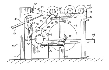
Referring to Figure 1, there is shown
generally at 10 a winding station for a paper making
machine. The winding station comprises a plurality of
support columns 11 and cross beams 120 Above the
columns 12 on top of the beams 11 is supported a first
pair of sloping racks or rails 14 are supported. It
should be understood that while only one side of the
,,,., . . ~ .
-',.' ~ , , , :
. . - ., . : ., ,:. :
,
'
1 3 1 1 7 3~ VDI 101~246
_ g
winding station is illustrated, the other side o~ the
station corresponds to the side described.
The rails 14 slope downwardly from the right
side of Figures 1 and 2 at a predetermined angle of
approximately 2. The rails 14 are spaced apart to
provide a track for supporting and guiding empty
reels 16 prior to these reels being loaded into a
winding position. The reels 16 are loaded onto the
first rails 14 by a crane (not shown). In Figure 3
each end of the reels includes a first groove 18
located between two collars 20 ~so as to provide a shoe
that runs over and along a corresponding rail 14. The
rails 14 have stops 22 located on an inside surface of
the rails that pivot under piston control (not shown)
to raise the stop into engagement with inner reel
collar 20 to halt movement of the reel along the
rails 14.
In Figure 1 the lower ends of the first
rails 14 axe shown pivotally connected to second
rails 24. The pivot connection is provided by a
hinge 26 having hinge ~rackets attached to respective
outside surfaces of rails 14 and 24. The hinge
joint 26 pivots about a pin that is oriented along a
vertical axis. ~he second rails 24 have an upper end
portion 28, a downwardly sloping portion 30 and a lower
end portion 32. In the position shown in Figure l (the
first position), the second rails 24 provide a
continuum of the track provided by tha first rails 14.
This allows the shoes of the reels 16 to pass from the
first rails 14 onto the second rails 30. The second
rails 24 may be pivoted about the vertical axis with
respect to the first rails 14 into a second position as
shown in Figure 2. In this second position for the
second rails 24, the reels 16 are prevented from moving
onto the second rails by the stops 22. Further due to
`" ' ' ' '
.
~ .
1 3 1 1 7 3 4 VDI 101-246
-- 10 --
the outward movement of the rails 24 at right angles to
the rails 14, the rails 24 would effectively engage the
outer collar 20 of the reel 16 in the event that the
stop 22 does not function. It is envisaged that it
would be feasible to have the rails 24 engage the outer
collar 20 of the reel 16 simultaneously with the
stop 22 engaging the inner collar 20 of the rael when
the rails 14 are in their second outwardly pivoted
position. Movement of the rails 24 relative to the
rails 14 is controlled by a hydraulic piston and
cylinder arrangement 25 with the cylinder pivotally
connected to the outside surface of tha rail 14 and the
piston pivotally connected to the outside surface of
the rail 24. The rails 24 are positioned in alignment
with the rails 14 to provide a continuum of the track
when the piston/cylinder arrangement is expanded and
the rails 24 extend outwardly at right angles to the
rails 14 when the piston/cylinder arrangement is
contracted.
Movement of the reel 16 over the second
rails 24 is controlled by a pair of lowering arms 34
(only one shown). The lowering arms 34 engage a
respective groove 19 ~see Figure 3) located at an end
of the reel 16 between the main body of the
reel 21 and the inside collar 20 of the reel. The
engagement of the lowering arms 34 in grooves l9 of the
reel 16 effectively locates the lowering arms adjacent
to and on the inside of second rails 24 so as to permit
the second rails to pivot outwardly. The lowering
arms 34 are pivotally connected at 36 to the supporting
structure of the left-most column 11 shown in the
drawings. The lowering arms are interconnected by an
elongated bar or shaft 38 (Figure 3) that spans the
width of the station between the rails 14 and 22.
Movement of lowering arms 34 is controlled
, ~ .
- :
- .
1 3 1 1 73 ~ VDI 101-246
-- 11 --
by respective hydraulic piston and cylinder
arrangements 40 shown pivotally connected to the
lowering arm at 42 and to the column 12 at 44. The
control of hydraulic pistons/cylinders 40 and the
interconnection of the lowering arms 34 via bar 38
ensures that the ends of a reel 16 uniformly descend
the second rails 24.
Bslow the second rails 24 is a driving
roll 46. The driving roll contacts the reel 16 and
drives the reel 16 as paper or web (not shown) is
rolled onto the empty reel. It should be understood
that a reel prestart device to start rotation o~ the
reel prior to it contacting the driving roll 46 is not
shown and that a cutting device to cut the continuous
paper web from the wound roll 48 is not shown.
The reel 16 descends the rails 24 with
groove 18 rolling onto a supporting shoe 56 of an
awaiting transfer arm 50 (one located at each end of
the reel). The transfer arm 50 includes a
cylinder/piston arrangement 52 which is pivotally
attached to a clamp or jaw 54. Transfer arm 50 further
includes a lower jaw 51 pivotally movable by
piston/cylinder arrangement 53. In Figure 2, the
cylinder/piston 52 is extended to pivot the jaw 54
about collar 20 and tha piston/cylinder arrangement 51
is extended bringing the lower jaw 53 up into
engagement with collar 20. Once the reel 16 has been
initially loaded on the driving roll 46, the wound
roll 48 moves out o~ the station 10 along lower
rails 58. The reel 16 is supported by the shoe 56 and
jaws 53 and 54 of the transfer arm mechanism 50. The
transfer arm 50 subsequently rotates about axis 60 in
the direction of arrow 61 thereby moving the reel 16
onto rails 58. The transfer mechanism controls the nip
pressure between the reel and the driving roll 46. At
.
~ 1 1 7;~
- VDI 101-246
- 12 -
this stage, the reel 16 is supported on lower
rails 58. A piston cylinder mechanism 70 and shoe
assembly 72 controls the nip pressure between the
driving roll 46 and paper wound on reel 16. As the
paper continues to wind on reel 16, the roll diameter
increases, increasing the distance between the axis of
drive roll 46 and reel 16. The piston/cylinder
arrangements 51, 52 of transfer arm 50, contract
pivoting jaws 53,54 out of engagement with collar 20
and trans~er arm 50 is rotated back into the position
shown in Figure 1. The rails 24 are then pivoted back
to the position shown in Figure 1 and arms 34 are
raised to ready the loader fQr the descent of the next
reel 16.
In accordance with the present invention the
transfer of the reel from the upper first rails 14 to
the lower winding position is accomplished by first
allowing the reel 16 to descend the rails 24 under the
control of the lowering arms 34 and the pistonJcylinder
hydraulic arrangement 40. As a result, the load
associated with the weight of the reel is shared by the
rails 24 and lowering arms 34. The reel is lowared off
the lower Pnd portions of the rails 24 into the
adjacent transfer arm 56. The piston/cylinders 51,52
are then expanded causing the jaws 53,54 to surround
the collars 20 of the reel 16. At this time, the
piston/cylinder 40 is contracted further so that the
arms 34 no longer engage the reel. The rails 24 are
then pivoted outwardly to their second position as
shown in Figure 2. This permits the transfer arm 56 to
rotate about axis 60 maintaining the reel 16 in contact
with the drive roll 46 and ultimately placing the reel
on the rails 58.
-