Note: Descriptions are shown in the official language in which they were submitted.
1 3 ~
METHOD FOR REDUCING SHEETING
DURING POLYMERIZATION OF ALPHA-OLEFINS
. BACKGROUND OF THE INVE~TION
Field of the Invention
This invention relates to a method for
reducing sheeting during polymerization of
alpha-olefins and more particularly to a method for
reducing sheeting during polymerization of
polyethylene.
SummarY of the Prior Art
Conventional low density polyethylene has
been historically polymerized in heavy walled
autoclaves or tubular reactors at pressures as high
as 50,000 psi and temperatures up to 300C or
higher. The molecular structure of high pressure,
low density polyethylene (HP-LDPE) is highly
complex. The permutations in the arrangement of
their simple building blocks are essentially
infinite. HP-LDPE's are characterized by an
intricate long chain branched molecular
architecture. These long chain branches have a
dramatic effect on the melt rheology of these
resins. HP-LDPE's also possess a spectrum of short
chain branches, generally 1 to 6 carbon atoms in
length. These short chain branches disrupt crystal
formation and depress resin density.
More recently, technology has been provided
whereby low density polyethylene can be produced by
fluidized bed technigues at l~w pressures and
temperatures by copolymerizing ethylene with various
'~
. ~
D-15695
131~
-- 2 --
alpha-olefins. These low pressure LDPE (LP-LDPE)
resins generally possess little, if any, long chain
pranching and are sometimes referred to as linear
LDPE resins. They are short chain branched with
branch length and frequency controlled by the type
- ~ and amount of comonomer used during polymerization.
As is well known to those skilled in the
art, low pressure, high or low density polyethylenes
can now be conventionally provided by a fluidized
~- bed process utilizing several families of catalysts
to produce a full range of low density and high
density products. The appropriate selection of
catalysts to be utilized depends in part upon the
type of end product desired, i.e., high density, low
density, extrusion grade, film grade resins and
other criteria.
The various types of catalysts which may be
used to produce polyethylenes in fluid bed reactors
can generally be typed as follows:
TY~e I. The silyl chromate catalysts disclosed in
U.S. Patent No. 3,324,101 to Baker and Carrick and
U.S. Patent No. 3,324,095 to Carrick, Karapinks and
Turbet. The silyl chromate catalysts are
characterized by the presence therein of a group of
the formula:
~ R n I
Si - 0 - Cr - O- _
I ~ n
LR O j
wherein R is a hydrocarbyl group having from 1 to 14
carbon atoms. The preferred silyl chromate
D-15695
_ 3 _
catalysts are the bis(triarylsilyl) chromates and
more preferably bis(triphenylsilyl) chromate.
This catalyst is used on a support such as
- : silica, alumina, thoria, zirconia and the like,
other supports such as carbon black,
micro-crystalline cellulose, the non-sulfonated ion
exchange resins and the like may be used.
TvPe II. The bis(cyclopentadienyl) chromium (II)
compounds disclosed in U.S. Patent No. 3,8~9,368.
These bis(cyclopentadienyl) chromium (II) compounds
have the following formula:
(,R )n~ (R~)n"
~ Cr
(H)5-n' . (H)5-
wherein R~ and R" may be the same or different C
to C20, inclusive, hydrocarbon radicals, and n'
and n" may be the same or different integers of 0 to
5, inclusive. The R' and R" hydrocarbon radicals
may be saturated or unsaturated, and can include
aliphatic, alicyclic and aromatic radicals such as
methyl, ethyl, propyl, butyl, pentyl, cyclopentyl,
cyclohex~l, allyl, phenyl and naphthyl radicals.
These catalysts are used on a support as
heretofor~ described.
TYPe III. The catalyst6 as described in U.S. ~atent
No. 4,011,3~2. These catalyst6 contain chromium and
titaniu~ ~n the form of oxides and, optionally,
fluorine and a support. The catalyst6 contain,
D-15695
1 3 ~ 9
-- 4 --
based on the combined weight of the support and the
chromium, titanium and fluorine, about 0.05 to 3.0,
and preferably about 0.2 to 1.0 weight percent of
chromium (calculated as Cr), about 1.5 to 9.0 and
preferably about 4.0 to 7.0, weight percent of
titanium (calculated as Ti), and 0.0 to about 2.5,
and prefereab`ly about 0.1 to 1.0 weight percent of
fluorine (calculated as F)
The chromium compounds which may be used for
the Type III catalysts include CrO3, or any
compound of chromium which is oxidizable to CrO3
under the activation conditions employed. At least a
portion of the chromium in the supported, activated
catalyst must be in the hexavalent state. Chromium
compounds other than CrO3 which may be used are
disclosed in U.S. Patent No. 2,825,721 and U.S.
Patent No. 3,622,521 and include chromic acetyl
acetonate, chromic nitrate, chromic acetate, chromic
chloride, chromic sulfate, and ammonium chromate.
The titanium compounds which may be used
include all those which are oxidizable to TiO2
under the activation conditions employed, and include
those disclosed in U.S. Patent No. 3,622,521.
The fluorine compounds which may be used
include HF, or any compound of fluorine which will
yield HF under the activation conditions employed.
- The inorganic oxide materials which may be
used as a support in the catalyst compositions are
D-15695
A
.
~ 3 ~
porous materials having a high surface area, that
is, a surface area in the range of about 50 to 1000
square meters per gram, and an average particle size
of about 20 to 200 microns. The inorganic oxides
which may be used include silica, alumina, thoria,
. ~ zirconia and other comparable inorganic oxides, as
well as mixtures of such oxides.
Type IV. The catalysts as described in U.S. Patent
~o. 4,302,566 in the names of F.J. Karol et al, and
entitled, "Preparation of Ethylene Copolymers in
Fluid 8ed Reactor" and assigned to the same assignee
as the present application. These catalysts
comprise at least one titani~m compound, at least
one magnesium compound, at least one electron donor
compound, at least one activator compound and at
least one inert carrier material.
The titanium compound has the structure
Ti (OR)aXb
wherein R is a Cl to Cl4 aliphatic or aromatic
hydrocarbon radical, or COR' where R' is a Cl to
Cl4 aliphatic or aromatic hydrocarbon radical; X
is Cl, Br, or I; a is O or l; b is 2 to 4 inclusive;
and a+b - 3 or 4.
The titanium compounds can be used
individually or in combination thereof, and would
include TiC13, TiCl4, Ti(OCH3)C13,
Ti(OC6H5)C13, Ti(OCOCH3)C13 and
Ti(ococ6Hs)cl3
The magnesium compound has the structure:
MgX2
wherein X is Cl, Br, or I. Such magnesium compounds
can be used individually or in combinations thereof
D-15695
1 3 ~ 7 ~
and would include MgC12, MgBr2 and MgI2.
Anhydrous MgC12 is ~he preferred magnesium
compound.
The titanium compound and the magnesium
compound are generally used in a form which w~
facilitate their dissolution in the electron donor
~ compound.
The electron donor compound is an organic
compound which is liquid at 25C and in which the
titanium compound and the magnesium compound are
partially or completely soluble. The electron donor
compounds are ~nown as such or as Lewis bases.
The electron donor compounds would include
such compounds as alkyl esters of aliphatic and
aromatic carboxylic acids, aliphatic ethers, cyclic
ethers and aliphatic ketones.
The catalyst may.be modified with a boron
halide compound having the structure:
BRcX'3-c
wherein R is an aliphatic or aromatic hydrocarbon
radical containing from 1 to 14 carbon atoms or OR',
wherein R' is also an aliphatic or aromatic
hydrocarbon radical containing from 1 to 14 carbon
atoms; X' is selected from the group consisting of
Cl and 8r, or mixtures thereof, and; c is O or 1
when R is an aliphatic or aromatic hydrocarbon and
O, 1 or 2 when R is OR'.
The boron halide compounds can be used
individually or in combination thereof, and would
include BC13, BBr3, B(C2Hs)C12, B( 2 s 2
2H5)2Cl~ B(C6H5)C12, B(oc6Hs)
(C6H13)C12~ B()C6H13)C12, and
D-15695
~ J~
-- 7 --
8(OC6H5)2Cl. Boron trichloride is the
particularly preferred boron compound.
The activator compound has the structure:
Al(R )cX dHe
wherein X' is Cl or ORl; Rl and R" are the same --
or different and are Cl to C14 saturated
hydrocarbon radicals, d is 0 to 1.5, e is 1 or 0,
and c+d+e s 3
Such activator compounds can be used
individually or in combinations thereof.
The carrier materials are solid,
particulate materials and would include inorganic
materials such as oxides of silicon and aluminum and
molecular sieves, and organic materials such as
olefin polymers, e.g., polyethylene.
TY~e V. Vanadium based catalysts. These type
catalysts generally include vanadium as the active
ingredient, one such type catalyst generally
comprises a supported precursor, a cocatalyst and a
promoter. The supported precursor consists
essentially of a vanadium compound and modifier
impregnated on a solid, inert carrier. The vanadium
compound in the precursor is the reaction product of
a vanadium trihalide and an electron donor. The
haiogen in the vanadium trihalide is chlorine,
bromine or iodine, or mixtures thereof. A
particularly preferred vanadium trihalide is
vanadium trichloride, VC13.
The electron donor is a li~uid, organic
Lewis base in which the vanadium trihalide is
soluble. The electron donor is selected from the
group consisting of alkyl esters of aliphatic and
D-15695
1 3 1 ~ J
- B -
aromatic carboxylic acids, alipha~ic esters,
aliphatic ketones, aliphatic amines, aliphatic
alcohols, alkyl and cycloalkyl ethers, and mixtures
, thereof. Preferred electron donors are alkyl and
cycloalkyl ethers, including particularly --~~
. ~ tetrahydrofuran. 8etween about 1 to about 20,
preferably between about 1 to about 10, and most
preferably about 3 moles of the electron donor are
complexed with each mole of vanadium used.
The modifier used in the precursor has the
formula:
MXa
wherein:
M is either boron or AlR(3 a) and wherein
each R is independently alkyl, provided
that the total number of aliphatic carbon
.atoms in any one R group may not exceed 14;
X is chlorine, bromine or iodine; and
a is 0, 1 or 2, with the provision that when
M is boron a is 3.
Preferred modifiers include Cl to C6
alkyl aluminum mono- and di- chlorides and boron
trichloride. A particularly preferred modifier is
diethyl aluminum chloride. About 0.1 to about 10,
and preferably about 0.2 to about 2.5, moles of
modifier are used per mole of electron donor.
The carrier is a solid, particulate porous
material inert to the polymerization. The carrier
consists essentially of silica or alumina, i.e.,
oxides of silicon or aluminum or mixtures thereof.
Optionally, the carrier mav contain additional
materials such as zirconia, thoria or other
D-15695
g
compounds chemically inert to the polymerization or
mixtures thereof.
The carrier is used--as a dry powder having
an average particle size of between about 10-to --
about 250, preferably about 20 to about 200, and ,
' most preferably about 30 to about 100, microns. The
porous carrier has a surface area of greater than or
equal to about 3, and preferably greater than or
equal to about 50, m2/g. A preferred carrier is
silica having pore sizes of greater than or equal to
about 80, and preferably greater than or equal to
about 100, angstroms. The carrier is predried by
heating to remove water, preferably at a temperature
of greater than or equal to about 600C.
The amount of carrier used is that which
will provide a vanadium content of between about
0.05 to about 0.5 mmoles of vanadium per gram (mmole
V/g), and preferably between about 0.2 to about 0.35
mmole V/g, and most preferably about 0.29 mmole V/g.
The carrier is ordinarily free of
preparative chemical treatment by reaction with an
alkylaluminum compound prior to the formation of the
supported precursor. Such treatment results in the
formation of aluminum alkoxides chemically bonded to
the carrier molecules. It has been discovered that
the use of such a treated carrier in the catalyst
composition and process is not only nonessential,
but instead results in undesirable agglomeration
when used in the preparation of high density
polyethylene (~0.94 g/cc), resulting in a
chunk-like, non-freely flowing product.
The.cocatalyst which can be employed for
D-15695
131~r~ r:
-- 10 --
the Type IV and Type V catalysts has the formula:
AlR3
wherein R is as previously defined in the definition
of M. Preferred cocatalysts include C2 to-GB
trialXylaluminum compounds. A particularly
preferred cocatalyst is triisobutyl aluminum.
- Between about 5 to about 500, and preferably between
about 10 to about 50, moles of cocatalyst are used
per mole of vanadium.
The promoter has the formula:
R' CX'
wherein:
R' is hydrogen or unsubstituted or
halosubstituted lower, i.e., up to about
- C6 containing, alkyl;
X' is halogen; and
b is 0, 1 or 2.
Between about 0.1 to about lO, and preferably
between about 0.2 to about 2, mcles of promoter are
used per mole of cocatalyst.
~ The catalyst is produced by first preparing
the supported precursor. In one embodiment, the
vanadium compound is prepared by dissolving the
vanadium trihalide in the electron donor at a
temperature between about 20C up to the boiling
point of the electron donor for a few hours.
Preferably, mixing occurs at about 65C for about 3
hours or more. The vanadium compound so produced is
then impregnated onto the carrier. Impregnation may
be effected by adding the carrier as a dry powder or
as a slur~y in the electron donor or other inert
solvent. The liquid is removed by drying at less
D-15695
1 3 ~
than about 100C for a few hours, preferably between
about 45 to about 90C for about 3 to 6 hours. The
modifier, dissolved in an inert solvent, such as a
hydrocarbon, is then mixed with the vanadium
impregnated carrier. The liquid is removed by
drying at temperatures of less than about 70C for a
~ few hours, preferably between about 45 to about
65C for about 3 hours.
The cocatalyst and promoter are added to
the supported precursor either before and/or during
the polymerization reaction. The cocatalyst and
promoter are added either together or separately,
and either simultaneously or sequentially during
polymerization. The cocatalyst and promoter are
preferably added separately as solutions in inert
solvent, such as isopentane, during polymerization.
In general, the above catalysts are
introduced together with the polymerizable
materials, into a reactor having an expanded section
above a straight-sided section. Cycle gas enters
the bottom of the reactor and passes upward through
a gas distributor plate into a fluidized bed located
in the straight-sided section of the vessel. The
gas distributor plate serves to ensure proper gas
distribution and to support the resin bed when gas
flow is stopped.
Gas leaving the fluidized bed entrains
resin particles. Most of these particles are
disengaged as the gas passes through the expanded
section where its velocity is reduced.
In order to satisfy certain end use
applications for ethylene resins, such as for film,
D-15695
131~ ~r
- 12 -
injection molding and roto-molding applications,
catalyst Types IV and V with alkyl aluminum
cocatalysts :~ave been used. However, attempts to
produce certain ethylene resins utilizing alkyl
aluminum cocatalysts with the Type IV and V
- ~ catalysts supported on a porous silica substrate in
certain fluid bed reactors, have not been entirely
satisfactory from a practical commercial
standpoint. This is primarily due to the formation
of "sheets" in the reactor after a period of
operation. The "sheets" can be characterized as
constituting a fused polymeric material.
It has been found that a static mechanism
is a contributor to the sheeting phenomena whereby
- ~ catalyst and resin particles adhere to the reactor
walls due to static forces. If allowed to reside
long enough under a reactive enyironment, excess
temperatures can result in particle fusion.
Numerous causes for static charge exist. Among them
are generation due to frictional electrification of
dissimilar materials, limited static dissipation,
introduction to the process of minute quantities of
prostatic agents, excessive catalyst activities,
etc. Strong correlation exists between sheeting and
the presence of excess static charges either
negative or positive. This is evidenced by sudden
changes in static levels followed closely by
deviation in temperatures at the reactor wall.
These temperature deviations are either high or
low. Low temperatures indicate particle adhesion
causing an insulating effect from the bed
temperature. High deviations indicate reaction
D-15695
7/J
taking place in zones of limited heat transfer.
Following this, disruption in fluidization patterns
is generally evident, catalyst feed interruption can
occur, product discharge systëm pluggage results,
and thin fused agglomerates (sheets) are noticed in
the granular product.
The sheets vary widely in size, but are
similar in most respects. They are usually about
1/4 to 1/2 inch thick and are from about one to five
feet long, with a few specimens even longer. They
have a width of about 3 inches to more than 18
inches. The sheets have a core composed of fused
polymer which is oriented in the long direction of
the sheets and their surfaces are covered with
granular resin which has fused to the core. The
edges of the sheets can have a hairy appearance from
strands of fused polymer.
It is therefore an object of the present
invention to provide a method for substantially
reducing or eliminating the amount of sheeting which
occurs during the low pressure fluidized bed
polymerization of alpha-olefins utilizing titanium
based compounds or vanadium based compounds as
catalyst with alkyl aluminum as cocatalysts.
These and other objects will become readily
apparent from the following description taken in
conjunction with the accompanying drawing which
generally indicates a typical gas phase fluidized
bed polymerization process for producing high
density and low density polyolefins slightly
modified to refle~t the present invention.
D-15695
d ~ 7 r
- 14 -
SUMMARY OF THE INVENTION
Broadly contemplated, the present invention
provides a method for reducing sheeting during
polymerization of alpha-olefins in a low pressure
fluidized bed reactor utilizing titanium or vanadium
~ ' based compounds as catalysts together with alkyl
aluminum cocatalysts which comprises determining the
electrostatic levels at the site of possible sheet
formations in said reactor; if negative
electrostatic levels are indicated then adding a
positive charge generating chemical additive to the
reactor said additive being selected from the group
consisting of alcohols containing up to 7 carbon
atoms, oxygen and nitric oxide; if positive
electrostatic levels are indicated in said reactor
then, adding a negative charge generating chemical
additive to the reactor said chemical additive being
a ketone containing up to 7 carbon atoms, said
positive or negative charge generating chemical
additive being added to said reactor as required in
an amount suficient to create and maintain neutral
static charges in said reactor.
BRIEF DESCRIPTION OF THE DRAWING
The sole figure of the drawing is a
schematic representation of the process of the
invention.
DESCRIPTION OF THE PREFERRED EMBODIMENTS
The amount and type of chemical additive
which is added to the reactor depends on the static
voltage within the reactor and can generally range
D-15695
rl '`
- 15 -
in an amount of from about 0.1 to about 25 ppm based
on monomer (preferably ethylene) feed.
The critical static voltage level for sheet
formation is a complex function of resin 6intering
temperature, operating temperature, drag forces in
- ~ the fluid bed, resin particle size distribution and -
recycle gas composition. The static voltage can be
reduced by a variety of conventional techniques such
as by treating the reactor surface to reduce static
electric generation by injection of an antistatic
agent to increase particle surface electrical
conductivity thus promoting particle discharging; by
installation of appropriate devices connected to the
reactor walls which are designed to promote
electrical discharging by creating areas of high
localized field strength, and by neutralization of
charges by the injection or creation of ion pairs,
ionC or charged particles of the opposite polarity
from the resin-bed.
According to the present invention, the use
of the particular type of chemical additive to the
gas phased low pressure polyethylene process will
assist in the reduction of agglomerate formation in
the fluidized bed. This is accomplished by a
reduction in the levels of positive or negative
static voltage depending on the type of additive,
which lowers particle adhesive forces in the
reaction system.
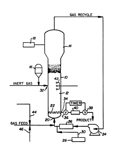
Referring particularly to the sole figure
of the drawing, a conventional fluidized bed
.eaction system for polymerizing alpha-olefins
D-15695
7 ~
includes a reactor 10 which consists of a reaction
zone 12 and a velocity reduction zone 14.
The reaction zone 12 includes a bed of
growing polymer particles, formed polymer particles
and a minor amount of catalyst particles fluidized
- ~ by the continuous flow of polymer,zable and
modifying gaseous components in the form of make-up
feed and recycle gas through the reaction zone. To
maintain a viable fluidized bed, the mass gas flow
rate through the bed is normally maintained above
the minimum flow required for fluidization, and
preferably from about 1.5 to about 10 times Gmf
and more preferably from about 3 to about 6 times
Gmf~ Gmf is used in the accepted form as the
abbreviation for the minimum gas flow required to
achieve fluidization, C.Y. Wen and Y.H. Yu,
"Mechanics of Fluidization", Chemical Engineering
Progress Symposium Series, Vol. 62, pg. 100-111
(1966).
It is highly desirable that the bed always
contains particles to prevent the formation of
localized "hot spots" and to entrap and distribute
the particulate catalyst throughout the reaction
zone. On start up, the reactor is usually charged
with a base of particulate polymer particles before
gas flow is initiated. Such particles may be
identical in nature to the polymer to be formed or
different therefrom. When different, they are
withdrawn with the desired formed polymer particles
as the first product. Eventually, a fluidized bed
of the desired polymer particles supplants the
start-up bed.
The appropriate catalyst used in the
fluidized bed is preferably stored for service in a
D-15695
reservoir 16 under a blanket of a gas which is inert
to the stored material, such as nitrogen or argon.
Fluidization is achieved by a high rate of
gas recycle to and through thè bed, typically in the
--5 order of about 50 times the rate of feed of make-up --
gas. The fluidized bed has the general appearance
- of a dense mass of viable particles in possible
free-vortex flow as created by the percolation of
gas through the bed. The pressure drop through the
bed is equal to or slightly greater than the mass of
the bed divided by the cross-sectional area. It is
thus dependent on the geometry of the reactor.
Make-up gas is fed to the bed at a rate
equal to the rate at which particulate polymer
product is withdrawn. The composition of the
make-up gas is determined by a gas analyzer 18
positioned above the bed. The gas analyzer
determines the composition of the gas being recycled
and the composition of the make-up gas is adjusted
accordingly to maintain an essentially steady state
gaseous composition within the reaction zone.
To insure complete fluidization, the
recycle gas and, where desired, part or all of the
make-up gas are returned to the reactor at base 20
below the bed. Gas distribution plate 22 positioned
above the point of return ensures proper gas
distribution and also supports the resin bed when
gas flow is stopped.
The portion of the gas stream which does
not react in the bed constitutes the recycle gas
which is removed from the polymerization zone,
preferably by passing it into velocity reduction
zone 14 abov~ the bed where entrained particles are
given an opportunity to drop back into the bed.
D-15695
r~ r
- 18 -
The recycle gas is then compressed in a
compressor 24 and thereafter passed through a heat
-exchanger 26 wherein it is s~ripped of heat of
reaction before it is returned to the bed. By
constantly removing heat of reaction, no noticeable
~ ~ temperature gradient appears to exist within the
upper portion of the bed. A temperature gradient
will exist in the bottom of the bed in a layer of
about 6 to 12 inches, between the temperature of the
inlet gas and the temperature of the remainder of
the bed. Thus, it has been observed that the bed
acts to almost immediately adjust the temperature of
the recycle gas above this bottom layer of the bed
zone to make it conform to the temperature of the
remainder of the ~ed thereby maintaining itself at
an essentially constant temperature under steady
conditions. The recycle is then returned to the
reactor at its base 20 and to the fluidized bed
through distribution plate 22. The compressor 24
can also be placed downstream of heat exchanger 26.
Hydroqen may be used as a chain transfer
agent for conventional polymerization reactions of
the types contemplated herein. In the case where
ethylene is used as a monomer the ratio of
hydrogen,'ethylene employed will vary between 0 to
about 2.0 moles of hydrogen per mole of the monomer
in the gas stream.
Any gas inert to the catalyst and reactants
can also be present in the gas stream. The
cocatalyst is added to the gas recycle stream
upstream of its connection with t.e reactor as from
dispenser 2B through line 30.
As is well known, it is essential to
D-15695
~- 3 ~ rJ ~
- 19 -
operate the fluid bed reactor at a temperature below
the sintering temperature of the polymer particles.
Thus to insure that sintering._will not occur,
operating temperatures below sintering temperature
are desired. For the production of ethylene
polymers, an operating temperature of from about 80
to 110C is preferably used to prepare products
having a density of about 0.94 to 0.97 while a
temperature of about 75 to 95C is preferred for
products having a density of about 0.91 to 0.94.
The fluid bed reactor is operated at total
pressures of up to about 270-350 psi.
The catalyst is injected into the bed at a
rate equal to its consumption at a point 32 which is
above the distribution plate 22. A gas which is
inert to the catalyst such as nitrogen or argon is
used to carry the catalyst into the bed. Injecting
the catalyst at a point above distribution plate 22
is an important feature. Since the catalysts
normally used are highly active, injection into the
area below the distribution plate may cause
polymerization to begin there and eventually cause
plugging of the distribution plate. Injection into
the viable bed, instead, aids in distributing the
catalyst throughout the bed and tends to preclude
the formation of localized spots of high catalyst
concentration which may result in the formation of
"hot spotE".
Under a given set of operating conditions,
the fluidized bed is maintained at essentially a
constant height by withdrawing a portion of the bed
as product at a rate equal to the rate of formation
of the particulate polymer product. Since the rate
D-15695
13 ~ g IJ
- 20 -
of heat generation is directly related to product
formation, a measurement of the temperature rise of
the gas across the reactor (the difference between
inlet gas temperature and ex~t gas temperature) is
~-S- determinative of the rate of particulate polymer -
formation at a constant gas velocity.
: The particulate polymer product is
preferably withdrawn at a point 34 at or close to
distribution plate 22. The particulate polymer
product is conveniently and preferably withdrawn
through the sequential operation of a pair of timed
valves 36 and 38 defining a segregation zone 40.
While valve 38 is closed, valve 36 is opened to emit
a plug of gas and product to the zone 40 between it
and valve 36 which is then closed. Valve 38 is then
opened to deliver the product to an external
recovery zone and after delivery, valve 38 is then
closed to await the next product recovery operation.
Finally, the fluidized bed reactor is
equipped with an adequate venting system tc allow
venting the bed during the start up and shut down.
The reactor does not require the use of stirring
means and/or wall scraping means.
The reactor vessel is normally constructed
of carbon steel and is designed for the operating
conditions stated above.
In order to better illustrate the problems
incident to the utilization of the Type IV
catalysts, reference is again made to the drawing.
The titanium based catalyst (Type IV) is introduced
into the reactor 10 at point 32. Under conventional
operations on certain resins, after a period of
time, sheets begin to form in reactor 10, at a site
D-15695
131~
- 21 -
in the reactor proximate the wall of the reactor and
located about a distance of one-half the reactor
diameter up from the base of the fluid bed. The
sheets of-fused resin begin to appear in segregation
~- 5 zone 40, rapidly plugging the system, causing the
reactor to be shut down. More characteristically -,
the sheeting begins after production equivalent to 6
to 10 times the weight of the bed of resin in
reactor 10.
The causes for sheeting have been discussed
extensively in U.S. Patent 4,532,311 and according
to the teachings in said patents, it is generally
believed that when the charge on the particles
reaches the level where the electrostatic forces
trying to hold the charged particle near the reactor
wall exceed the drag forces in the bed trying to
move the particle away from the wall, a layer of
catalyst containing, polymerizing resin particles
forms a non-fluidized layer near the reactor wall.-
Heat removal from this layer is not sufficient to
remove the heat of polymerization because the
non-fluidized layer near the wall has less contact
with the fluidizing gas than do particles in the
fluidized portion of the bed. The heat of
polymerization increases the temperature of the
non-fluidized layer near the reactor wall until the
particles melt and fuse. At this point other
particles from the fluidized bed will stick to the
fused layer and it wi}l grow in size until~it comes
loose from the reactor wall. The separation of a
dielectric from a conductor (the sheet from the
reactor wall) is known to generate additional static
electricity thus accelerating subsequent sheet
formation.
D-15695
` ~3~7~,
- 22 -
As discussed in U.S. Patent 4,532,311, the
art teaches various processes whereby static voltage
can be reduced or eliminated. These comprise (1)
reducing the rate of charge generation, (2)
S increasing the rate of discharge of electrical
charge, and (3) neutralization of electrical
charge. Some processes suited for use in a
fluidized bed comprise (1) use of an additive to
increase the conductivity of the particles thus
providing a path for discharging, (2) installation
of grounding devices in a fluidized bed to provide
additional area for discharging electrostatic
charges to ground, (3) ionization of gas or
particles by electrical discharge to generate ions
to neutralize electrostatic charges on the
particles, and (4) the use of radioactive sources to
produce radiation that will create ions to
neutralize electrostatic charges on the particles.
The application of these technigues to a commercial
scale, fluidized bed, polymerization reactor may not
be feasible or practical. Any additive used must
not act as a poison to the polymerization catalyst
and must not adversely affect the quality of the
product.
As mentioned previously, we have discovered
a group of chemical additives which generate either
positive or negative charges in the reactor,
depending on the type additive, and advantageously
these additives are employed in amounts which do not
significantly poison the polymerization catalyst nor
adversely affect the quality of the products. We
have further found that by carefully monitoring the
electrostatic levels in the reactor, that the
D-15695
i3~ ~rl~
- 23 -
additives which generate either positive or negative
charges can be added responsive to the charges in
the reactor so as to maintain the electrostatic
charges substantially at neutral levels thereby
reducing or avoiding sheeting.
The chemical additives contemplated for use
in the present invention are as explained previously
those which generate positive charges in the reactor
and are selected from the group consisting of
alcohols containing up to 7 carbon atoms, oxygen and
nitric oxide or those which generate a negative
charge in the reactor such as a ketone containing up
to 7 carbon atoms preferably acetone and methyl
isobutylketone. Of the positive generating charge
chemical additive, the most preferred is methanol.
Of the nesative generating charge chemical additive,
the most preferred is methyl isobutyl ketone.
Although as mentioned previously, amounts
of positive or negative charge generating chemical
additive in the range of about 0.1 to about 25 ppm
based on monomer feed can be employed, it is
preferred to employ amounts of chemical additive
which generate sufficient positive or negative
charges to neutralize negative or positive static
charges, respectively.
Static voltage in the reactor can be
monitored near the reactor wall by one or more
static voltage indicators 42 inserted into the
reactor bed approximately five feet above the
distributor plate in the range of -15,000 to +15,000
volts. With reaction in progress, changes in static
voltage levels from neutral to positive can be
D-15695
131~ ~7 ~
- 24 -
counteracted by feed of the negative charge
generating chemical additive to the ethylene stream
(gas feed) through line 44. Alternatively changes
in static voltage levels from neutral to negative
can be counteracted by feed of positive generating
- ~ additive ~o the gas feed through line 46. If this -,
is not performed, impending agglomerate formation
will likely create a proçess upset. Care must be
exercised to avoid excessive chemical additives
which can result in unwanted static voltage levels.
The system is operated with various
sensors, flow and check valves which are common in
the art and hence not illustrated.
The polymers to which the present invention
is primarily directed and which cause the sheeting
problems above referred to in the presence of
titanium or vanadium catalysts are linear
homopolymers of ethylene or linear copolymers of a
major mol percent (>90~) of ethylene, and a minor
mol percent (<10%) of one or more C3 to C8 alpha
olefins. The C3 to C8 alpha olefins should not
contain any branching on any of their carbon atoms
which is closer than the fourth carbon atom. The
preferred C3 to C8 alpha olefins are propylene,
butene-l, pentene-l, hexene-l, 4-methylpentene-1,
heptene-l, and octene-l. This description is not
intended to exclude the use of this invention with
alpha olefin homopolymer and copolymer resins in
which ethylene is not a monomer.
The homopolymers and copolymers have a
density ra~ging from about 0.97 to 0.91. The
density of the copolymer, at a given melt index
level is primarily regulated by the amount of the
D-15695
1 3 ~ 7 i
- 25 -
C3 to C8 comonomer which is copolymerized with
the ethylene. Thus, the addition of progressively
larger amounts of the comonomers to the copolymers
results in a progressive lowering of the density of
the copolymer. The amount of each of the various
- ~ C3 to C8 comonomers needed to achieve the same
result will vary from monomer to monomer, under the
same reaction conditions. In the absence of the
comonomer, the ethylene would homopolymerize.
The melt index of a homopolymer or
copolymer is a reflection of its molecular weight.
Polymers having a relatively high molecular weight,
have relatively high viscosities and low melt index.
In a typical mode of utilizing the subject
invention to reduce sheeting, a reactor vessel such
as shown in Figure 1 and which is susceptible to
sheeting problems by the polymerization of the above
described materials utilizing Type IV and Type V
catalysts with an alkyl alum-num cocatalyst is
partially filled with granular polyethylene resin
which is purged with a non-reactive gas such as
nitrogen and is fluidized by circulating said
non-reacting gas through the reactor at a velocity
above the minimum fluidizing velocity (Gmf) of the
granular polyethylene and preferably at 3 to 5 Gmf.
The reactor is brought up to operational
temperatures by the gas and the reaction is started
by introducing the catalyst and cocatalyst to the
reactor. During reaction, static voltage levels may
often approach those levels which cause sheeting.
The vc:tage levels in the reactor are determined and
monitored and chemical additive responsive to the
type charge desired for neutralization is added to
D-15695
1 3 1 ~ ~rlr
- 26 -
the gas feed stream through lines 44 or 46 and the
procedure is continued until the static voltage
levels are substantially neutralized.
Having set forth the general nature of the
invention, the following examples illustrate some
- ' specific embodiments of the invention. It is to be
understood, however, that this invention is not
limited to the examples, since the invention may be
practiced by the use of various modifications.
Examples 1 and 2 were conducted in a
conventional bed reactor. The catalyst used was a
Ziegler type, titanium based catalyst supported on
porous silica produced as described earlier as Type
IV. The cocatalyst used was triethyl aluminum. The
products made in the examples were copolymers of
ethylene and l-butene. Hydrogen was used as a chain
transfer agent to control the melt index of the
polymer.
Exam~le 1
A fluidized bed reactor was started up at
operating conditions desigr,ed to produce a film
grade low density ethylene copolymer product having
a density of 0.918, a melt index of 1.0, and a
sticking temperature of 104C. The reaction was
started by feeding catalyst to the reactor
precharged with a bed of granular resin similar to
the product to be made. The catalyst was a mixture
of 5.5 parts titanium tetrachloride, 8.5 parts
magnesium chloride and 14 parts tetrahydrofuran
deposited on 100 parts Davison grade 955 silica
which had been dehydrated at 600C and treated with
four parts triethylaluminum prior to deposition and
D-15695
1 3 1 ~
~ 27 -
was activated with thirty-five parts tri-n-hexyl
aluminum subsequent to deposition. Prior to
starting catalyst feed, the reactor and resin bed
were brought up to the operating temperature of
85C, were purged of impurities by circulating
- ~ nitrogen through the resin bed. Ethylene, butene
and hydrogen concentrations were established at 53,
24, and 11%, respectively. Cocatalyst was fed at a
rate of 0.3 parts triethylaluminum per part of
catalyst.
~eactor start-up was normal. After
producing product for twenty-nine hours and
eguivalent to 6-1/2 times the weight of the
fluidized bed, temperature excursions of 1 to 2C
above bed temperature were observed using
thermocouples located just inside the reactor wall
at an elevation of 1/2 reactor diameter above the
gas distributor plate. Prior experience had shown
that such temperature excursions are a positive
indication that sheets of resin are being formed in
the fluidized bed. Concurrently, bed voltage
(measured using an electrostatic voltmeter connected
to a 1/2 inch diameter spherical electrode located
one inch from the reactor wall at an elevation of
1/2 reactor diameter above the gas distributor
plate) increased from a reading of approximately
+1500 to +2000 volts to a reading of over +5000
volts and then dropped back to +2000 volts over a 3
minute period. Temperature and voltage excursions
continued for approximately 12 hours and increased
in frequency and magnitude. During this period,
sheets of fused polyethylene resin began to show up
in the resin product. Evidence of sheeting became
D-15695
1 3 ~
- 28 -
more severe, i.e., temperature excursions increased
to as high as 20C above bed temperature and stayed
high for extended periods of time and voltage r
e~cursions also became more frequent-. The reactor
-5 was shut down because of the extent of sheeting.
.- Exam~le 2
The fluidized bed reactor used in Example 1
was started up and operated to produce a linear low
density ethylene copolymer suitable for extrusion or
rotational molding and having a density of 0.934, a
melt index of 5 and a sticking temperature of
118C. The reaction was started by feeding catalyst
similar to the catalyst in Example 1 except
activated with 28 parts tri-n-hexylaluminum, to the
reactor precharged with a bed of granular resin
similar to the product to be made. Prior to
starting catalyst feed the reactor and the resin bed
were brought up to the operating temperature of
85C, and were purged of impurities with nitrogen.
The concentration of ethylene (52%), butene (14%),
hydrogen (21~) were introduced into the reactor.
Cocatalyst triethylaluminum was fed at 0.3 parts per
part of catalyst. The reactor was operated
continuously for 48 hours and during that period
produced resin equivalent to 9 times the amount of
resin contained in the bed. After this 48 hour
period of smooth operation, sheets of fused resin
began to come out of the reactor with the normal,
granular product. At this time voltages measured
1/2 reactor diameter above the distributor plate
averaged +2000 volts and ranged from 0 to +lC 000
volts, while the skin thermocouples at the same
D-15695
1 ~ ~L ~ ~ ri '~'
-- 29 --
elevation indicated excursions of >15C above the
bed temperature. Two hours after the first sheets
were noted in the product from the reactor, it was
necessary to stop feeding cata~yst and cocatalyst to
~5 the reactor to reduce the resin production rate
because sheets were plugging the resin discharge
system. One hour later, catalyst and cocatalyst
feeds were restarted. The production of sheets
continued and after two hours catalyst and
cocatalyst feed were again stopped and the reaction
was terminated by injecting carbon monoxide. The
voltage at this time was > I 12, 000 volts and the
thermocouple excursions continued until the poison
was injected. In total, the reactor was operated
for 53 hours and produced 10-1/2 bed volumes of
resin before the reaction was stopped due to
sheeting.
The following Examples illustrate the
prevention of sheeting by adding the chemical
additive to the gas feed during periods of high
voltage in the reactor.
ExamPle 3
.
Copolymerization of ethylene and butene was
6ustained in a fluidized bed reactor. The product
copolymer was a film grade resin of 0.918
grams/cm3 and a melt index of 1 dg/min. The
catalyst consisted of a mixture of 5 parts TiC13
1/3 AlC13, 7 parts MgC12, and 17 parts
tetrahydrofuran deposited on 100 parts of Davison
grade 955 silica. The silica had been dehydrated at
600C and treated with 5.7 parts triethylaluminum
prior to disposition and activated with 32 parts
D-15695
- 30 -
- tri-n-hexyl aluminum and 11 parts diethylaluminum
chloride subsequent to disposition. The co-catalyst
triethylaluminum, was fed at a sufficient rate to
maintain molar ratio of Al to Ti of- 30 to 1. The
fluidized bed was maintaired at a temperature of
88C. Concentrations of ethylene, butene, and
- hydrogen in the reactor were 46, 16, and 14 mole
percent, respectively. Resin was periodically
withdrawn from the reactor in order to maintain a
constant fluidized bed height within the reactor.
Catalyst was fed directly into the fluidized bed and
all other feeds were introduced into the cycle gas
stream downstream of both the compressor and heat
exchanger.
Static voltage was measured in the
fluidized bed by monitoring the voltage on a
hemispherical steel probe located one inch from the
inside wall, and one bed diameter above the
distributor plate. The static voltage in the
reactor was -500 volts.
A stream of nitrogen saturated with
methanol was then fed to reactor recycle at a point
just upstream of the bottom head of the reactor.
The methanol addition started to drive the static
voltage in the positive direction.
When the rate of methanol addition to the
cycle was 0.4 ppm per part ethylene feed to the
cycle, the static voltage was reduced to zero
volts. When the rate of methanol addition was
increased further to 0.9 ppm per part ethylene
addition to the cycle, the static voltage rose to
+600 volts. By properly adjusting the flow rate of
methanol to the reactor in response to readings from
D-15695
7r
- 31 -
the static probe, the voltage was maintained in the
range of +/- 100 volts.
By operation in this manner, no sheets or
chunks of fused resin appeared in the product resin
- 5- withdrawn from the reactor. Care was taken to keep
from adding too much methanol and thus driving the
~ static voltage too far positively, Likewise, when
the voltage started to drift more negatively,
additional methanol was added to the reactor. It
was found that there was no loss of catalyst
productivity when methanol was added to the reactor
to control negative static. Reactor operation was
smooth with no indications of sheet formation when
methanol was used to control negative static voltage.
Example 4
A fluidized bed reactor was started up at
operating conditions designed to pro~uce a film
grade low density ethylene copolymer product having
a density of 0.918, a melt index of 1.0 dg/min, and
a sticking temperature of 104C. The reaction was
started by feeding catalyst to the reactor
precharged with a bed of granular resin similar to
the product to be made. The catalyst was a mixture
of S parts titanium trichloride, 1.7 parts aluminum
chloride, 8 parts magnesium chloride, and 16 parts
tetrahydrofuran deposited on 100 parts Davison grade
955 silica which had been dehydrated at 600~C and
treated with five parts triethylaluminum prior to
deposition and was activated with thirty two parts
tri-n-hexyl aluminum and twelve parts
diethylaluminum chloride subsequent to deposition.
Prior to starting catalyst feed, the reactor and
D-15695
13~7~J
- 32 -
resin bed were brought up to the operating
temperature of 89C and were purged of impurities by
circulating nitrogen through the resin bed.
Ethylene, butene and hydroge~ concentrations were
--5 established at 51, 23 and 10%, respectively,
Cocatalyst was fed at a rate of 0.3 parts
- triethylaluminum per part catalyst.
At the time when catalyst was first fed to
the reactor, the static voltage in the fluidized bed
was -4500 volts. Static voltage was measured in the
fluidized bed by monitoring the voltage on a
hemispherical steel probe located one inch from the
inside wall and one half bed diameter above the
distributor plate.
At this time, just subsequent to the
initiation of catalyst feed, a saturated mixture of
ethanol in nitrogen at 20C was fed to the recycle
stream just upstream to the inlet to the reactor
vessel. The ethanol addition started to reduce the
amount of negative static present. The flow of
ethanol in nitrcgen was controlled to hold the
static voltage in the range of +/-200 volts. The
amount of ethanol required varied between 0.6 and
1.3 ppm ethanol per part ethylene feed to the
recycle stream. Eventually, positive static started
building in the reactor and the amount of ethanol
addition was continuously reduced in order to keep
from forming unwanted positive static. Ethanol flow
to the reactor was used successfully during the next
3 days to eliminate negative static in response to
readings from the static probe. At no time, were
there ary sheets or fused chunks of polymer found in
the product resin withdrawn from the reactor. In
D-15695
7 ~
- 33 -
addition, reactor operation was smooth and there
were no indications of sheet formation.
Exam~le 5 - ~ -
- : The fluidized bed reactor described in
Example 4 was again started up at operating
conditions designed to produce a film grade low
density ethylene copolymer product having a density
of 0.918, a melt index of 1.0, and a sticking
temperature of 104C. The reaction was started by
feeding catalyst to the reactor precharged with a
bed of granular resin similar to the product to be
made. The catalyst was the same catalyst as
described in Example 4. Prior to starting catalyst
feed, the reactor and resin bed were brought up to
the operating temperature of 89C and were purged of
impurities by circulating nitrogen through the resin
bed. Ethylene, butene and hydrogen concentrations
were established at 49, 22, and 10% respectively.
Cocatalyst was fed at a rate of 0.3 parts
triethylaluminum per part catalyst.
At the time when catalyst was first fed to
the reactor, the static voltage in the fluidized bed
was -3500 volts. Static voltage was measured in the
fluidized bed by monitoring the voltage on a
hemispherical steel probe located one inch from the
inside wall and one half bed diameter above the
distributor plate.
At this time, just subsequent to the
initiation of catalyst feed, a saturated mixture of
isopropanol in nitrogen at 30C was fed to the
recycle stream just upstream of the inlet to the
reactor vessel. The isopropanol addition started to
D-15695
131~
- 34 -
reduce the amount of negative static present. The
flow of isopropanol in nitrogen was controlled to
hold the static voltage in the range of +/- 200
' volts. The amount of isopropanol required varied
between 1.1 and 4.1 ppm per part ethylene feed to
the recycle stream. Isopropanol was used
~ successfully during the next 2 days to eliminate
negative static in response to readings from the
static probe. At no time, was any there indication
of sheet formation nor any sheets or fused chunks of
polymer found in the product resin withdrawn from
the reactor. The start up was very smooth while
using isopropanol to control negative static.
Example 6
Co-polymerization of ethylene and butene
was sustained in a fluidized bed reactor. The
product copolymer was a film grade resin of 0.918
grams/cm3 and a melt index of 1 dg/min. The
catalyst consisted of a mixture of 5 parts titanium
trichloride, 1.7 parts aluminum chloride, 8 parts
magnesium chloride, and 16 parts tetrahydrofuran
deposited on 100 parts of Davison grade 955 silica.
The silica had been dehydrated at 600C and treated
with 5.7 parts ~riethylaluminum prior to disposition
and activated with 32 parts tri-n-hexyl aluminum and
11 parts diethylaluminum chloride subsequent to
deposition. The co-catalyst triethylaluminum, was
fed at a sufficient rate to maintain molar ratio of
Al to Ti of 30 to 1. The fluidized bed was
maintained at a temperature of 88C. Concentrations
of ethylene, butene, and hydrogen in the reactor
were 46, 16, and 14 mole percent, xespectively.
D-15695
r~ ~
Resin was periodically withdrawn from the reactor in
order to maintain a constant fluidized bed height
within the reactor. Catalyst was fed directly into
the fluidized bed and all other feeds were
introduced into the cycle gas stream downstream of
both the compressor and heat exchanger.
Static voltage was measured in the
fluidized bed by monitoring the voltage on a
hemispherical steel probe located one inch from the
inside wall, and one bed diameter above the
distributor plate.
The static voltage in the reactor was
steady at + 50 volts. At this time a mixture of 10%
nitric oxide in nitrogen was fed to the recycle
stream just upstream of the inlet to the bottom of
the reactor. The nitric oxide addition caused the
static voltage to immediately shift positively. It
was found that the amount of positive static voltage
generated was proportional to the amount of nitric
oxide fed to the reactor. A feedrate of 1.9 ppm
nitric oxide per part ethylene feed to the reactor
caused + 4S00 volts of static. At voltages above +
4000 volts, a temperature excursion to 6C above bed
temperature was observed using a thermocouple
located inside the reactor wall at an elevation of
1/2 reactor diameter above the gas distributor
plate. Experience has shown that such temperature
excursions are a positive indication that a sheet of
resin was formed in the fluidized bed at this time.
The amount of positive static was reduced by
reducing the flow ~te of nitric oxide to the
recycle stream and the temperature indication
immediately returned to the normal reading of 86C,
indicating that sheet formation had stopped.
D-15695
- 36 -
ExamE~le 7
The fluidized bed reactor used in Example 6
was used to evaluate the effect of oxygen addition
upon static voltage. The reactor was operating and
~-5~ the static voltage in the fluidized bed was -~00
volts. A mixture of 7.5% oxygen in nitrogen was fed
- to the recycle piping just upstream of the inlet to
the bottom of the reactor vessel. An oxygen
feedrate of 0.2 ppm per part ethylene feed to the
reactor caused the voltage to be reduced to zero
volts. By controlling the feed rate of oxygen to
the recycle stream in response to readings from the
static probe in the fluidized bed, the static
voltage was controlled between +/- 100 volts. When
feed rates above 0.25 ppm oxygen per part ethylene
were introduced to the recycle stream, the static
voltage began to rise positively. Care was taken in
order to keep from overfeeding oxygen and thus
causing unwanted positive sta~ic. The productivity
2C of the catalyst was unaffected by oxygen addition to
the recycle stream in amounts up to 0.25 ppm. By
eliminating the negative voltage present in the
reactor and controlling the voltage near zero volts
using oxygen addition, sheeting did not occur in the
reactor.
ExamPle 8
The fluidized bed reactor used in Example 6
was further used to examine the effect of acetone on
static voltage and sheet formation in the fluidized
bed. The static voltage in the reactor was +300
volts. At this time, a stream of nitrogen saturated
with acetone at 25C was fed to the recycle stream
D-15695
131~7~
- 37 -
just upstream of the inlet to the bottom of the
reactor vessel. An acetone feedrate of 2.9 ppm per
part ethylene feed to the reactor caused the voltage
, to be reduced to zero. Further increases in the
~ 5 acetone feed rate caused unwanted negative static to ~~
. ~ appear. By controlling the flow rate of acetone to
~ the recycle gas in response to readings from the
static probe, the voltage in the fluidized bed could
be controlled between positive 50 and negative 50
volts. Care was taken in order to keep from
overfeeding acetone and thus causing unwanted
negative static. The productivity of the catalyst
was unaffected by the use of acetone. No sheets or
fused chunks of polymers were found in the product
15 - resin removed from the reactor while using acetone
to control the static voltage in the reactor. In
general, reactor operation was excellent while
controlling the static voltage. -
ExamPle 9
The fluidized bed reactor used and
described in Example 6 was further used to examine
the effect of methyl isobutyl ketone ~MIBK) on
static voltage and sheet formation in the reactor.
The static voltage in the reactor was + 400 volts
initially. At this time, a stream of nitrogen
saturated with MIBK at 20C was fed to the recycle
stream just upstream of the inlet to the bottom of
the reactor vessel. A MIBK feed rate of 3.4 ppm per
part ethylene feed to the reactor caused the voltage
to be reduced to zero volts. Further increases in
~he MIBK feed rate caused negative static to
appear. By controlling the flow rate of MIBK to the
D-15695
1 3 ~
- 38 -
recycle gas in response to readings from the static
probe, the voltage in the fluidized bed could be
controlled to within +/- 50 volts of zero. Care was
taken in order to keep from overfeeding MIBR and-5~ ' thus causing unwanted negative static. The
productivity of the catalyst was unaffected by the
- use of MI8K. No indication of sheet formation was
found nor were any sheets or chunks found in the
product resin removed from the reactor while MIBK
was used to control the static voltage level in the
fluidized bed.
D-15695