Note: Descriptions are shown in the official language in which they were submitted.
1~1 1927
1 259~3-15
A WATCH MOUNTED ON A CLIP
FIELD OF THE INVENTION
The present invention relates to a watch mounted on an
arm of a clip so as to be rotatable and removable.
BACKGROUND OF THE INVENTION
A clock having these properties is known from Canadian
Patent 1,117,777, of February 9, 1982. The clock described in
this patent is a relatively large table clock and has a rounded
form, at least on the side opposite the time indicating means, and
it is retained by magnets in a housing which may be fixed onto a -
branch of a clip. Due to the fact that the clock is retained in -~
this housing by magnets, it may be rotated and removed easily. If --
such a method of securement can be conceivable for a relatively
large and heavy table clock, it is not applicable to a small watch
which may be worn either secured to clothes or secured to a chain ~-~
around the neck. In addition, this known method of securement -~
does not lend itself to a relatively cheap mass-produced product.
U.S. Patent 4,508,459, of April 2, 1985, describes a 'A" ' ''
clock substantially comprising a clock body and a case in which
the clock body is rotatably mounted, thereby permitting the clock -
to be used either as a wall clock or as a table clock. This clock
is not intended to be worn secured to clothes or to a chain around
the neck. Finally, published German Patent Application DE-A-3 143
546 of June 3Q, 1983 describes an electronic, digital watch which ~
is disposed in a branch of a U-shaped clip and may be secured to ~ -
clothes. Since the indicating means of this digital watch is
fixed relative to the arm of the clip, this watch can only be
secured to clothes in a single manner, to ensure that the
indicating means can be easily read. ~
131 1~7
2 25943-15
OBJECT OF THE INVENTION
Consequently, the object of this present invention is to
provide a watch which is mounted on an arm of a clip so as to be
rotatable and removable, can be mass-produced and at a relatively
low cost and can be worn either secured to an item of clothing or
secured to a chain for wearing around the neck, or can be placed
on a table.
S~MMARY OF THE INVENTION
According to the present invention there is provided
in combination, a clip formed of two arms connected by a hinge
means, and a watch having a generally circular case mounted on one
of said arms so as to be rotatable and removable, wherein the : .
circumference of the case of said watch is provided with ribs and
wherein the upper arm of said clip includes an opening for -
receiving said watch, such opening being provided with shoulders .
for retaining said ribs and being disposed, relative to the hinge
of said clip, on the end which is pressed to open same, each of
said arms having a portion thereof adapted for gripping in -
opposing relation to the other arm, each of said gripping portions
being provided with a transverse concavity that is generally semi-
circular in cross section, additionally including a blocking bar : .
with an extended figure of eight cross section which can be
inserted into said transverse concavities provided in the gripping
portion of the clip, the bar being provided, in its central
portion with a loop which is oriented towards one side with a
transverse opening for receiving a small chain.
1311921 : -
2a 25943-15
The invention also comprises in combination, a clip
formed of two arms connected by a hinge means, and a watch having
a generally circular case mounted on one of said arms so as to be
rotatable and removable, wherein the circumference of the case of
said watch is provided with ribs and wherein the upper arm of said
clip includes an opening for receiving said watch, such opening
being provided with shoulders for retaining said ribs and being
disposed, relative to the hinge of said clip, on the end which is ~-
pressed to open same, each of said arms having a portion thereof ;
adapted for gripping in opposing relation to the other arm, each
of said gripping portions being provided with a transverse `
concavity that is generally semi-circular in cross section, ~
additionally including a securing bar having an extended cross ` -
section with a large diameter approximately equal to the diameter ~-
of the opening formed by said transverse concavities provided in
the gripping portion of the clip, and being provided, on both
sides and externally of the clip, with a securing portion having a
collar and an eyelet for receiving a small chain.
BRIEF DESCRIPTION OF THE DRAWINGS
The invention will be described, by way of example, in
more detail with reference to the accompanying drawings. In the
drawings:
Fig. l is a view of the object of the invention from
above;
Fig. 2 is a side elevational view of Fig. l; -
Fig. 3 is a cross-sectional view taken along the line
III-III of Fig. 1,
. ~
2 7
Fig. 4 is a cross-sectional view taken along the
line IV-IV of Fig. 2;
Fig. 5 is a cross-sectional view taken along the
line V-V of Fig. 3;
Fig. 6 shows a blacking bar in the gripping portion
of the clip;
.
Fig. 7 shows, in detail and on a large scale, the - -
blocking bar of Fig. 6;
Fig. ~ shows a securing bar inserted in the gripping
portion of the clip; and -
-
Fig. 9 is a front view of the securing bar shown in
Fig. ~.
DESCRIPTIO~ OF PREFERRED EM~ODIMENTS
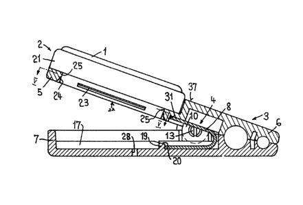
ZO Fig. 1 shows the watch 1 assembled in a case Z and mounted
in a clip 3. As regards size, the clip may have a length of
50 mm and a width of approximately Z7 mm. The case and
the clip are preferably moulded from plastics material. This
is advantageous, on the one hand, to facilitate mass-
Z5 production and, on the other hand, to obtain a watch and a
clip which are very light in weight and comfortable to wear.
As can be seen particularly from Figs. 2 and 3, it should be
remarked that, with regard to the hinge 4 of the clip, the
watch is situated on the end where one presses on the
arm 5 of the cllp, and it is not situated on the gripping
portion 6 of the clip. This is advantageous, in that the
clip, together with the watch, may also be placed on a
table, inter alia, on the lower arm 7 of the clip, so that
the face of the watch is perfectly legible.
131lq27 ~ :
- 4 -
Figs. 3 and 4 show the component parts of the clio, -
and it is apparent that the process for assembling this
clip is extremely simple. In addition to having the
upper arm 5 and the lower arm 7, the clip comprises a -
U-shaped leaf spring ~. On each side of the hinge 4,
there is an eyelet 9 in the upper arm 5 and an eyelet 10 ~ -
in the lower arm 7, the eyelet 9 being disposed near to
the eyelet 10, and both eyelets having openings 11 and
12 respectively, which each accommodate a luy 13
having, on its front, inwardly orientated portion, a slot
14 for increasing the flexibility and a retaining collar
15. :" ~'
The assembly process is shown in Figs. 3 and 4.
The two arms are superposed one above the other until the
two openings 11 and 12 lie opposite one another,
and the two lugs 13 are moved until their collar 15 is
situated behind the eyelet 10. Once the lug 13 is
engaged in this manner, it cannot be disengaged without
destroying the lug or the eyelets. Due to the fact that
the head 16 of the lug lies flush with the lateral faces
of the two branches of the clip, the risk of the lugs
disengaging is further reducéd and, in addition, this
heed 16 serves as a decorative element. Once the lugs
are in place, the spring ~ i9 inserted and, to facilitate
its insertion, the inner surface of the lower arm is
provided with two ribs 17. The spring ~ is held in -
place in the lower arm 7 by a frame comprising two lateral
walls 1~ and a transverse wall 19, and the spring B i~
held in place in the inner surface of the upper arm 5 by
a lateral wall 31. To facilitate insertion of the spring,
the surface ZO of the transverse wall 19 may be biassed.
The watch 1 i9. situated in a case Z comprising an upper
ring 21 and z lower ring 22. The lower ring ZZ is provided -
. ~ ',
::
"-.
131 1927
with bwo ribs 23 which are disposed opposite one another,
each rib extending over approximately one quarter of ~ -
the circumference and being inserted into a corresponding
opening 24 in the upper branch of the clip, this
opening being provided with two shoulders 25 which have
a length which is almost equal to that of the ribs 23.
The ribs, on the one hand, and the shoulders, on the
other hand, are disposed in such a manner that the watch,
together with the case, can only be inserted or removed
in only one specific position, fdr example, in the 14-10
position. It is, of course, possible for any other position
to be specified. To protect the rim Z69 it is preferable
to provide a protection means 27 with grooves which permit
the watch to be easily rotated with the help of this
protection means. As is apparent from Fig.2, the watch with
its case does not greatly exceed the surface 37 of the
upper arm which is stepped.
The watch in combination with the clip, may be secured
Zo by different methods so that it can be worn. A first
method is to secure the lower arm 7 to the lapelof a jacket
by means of a Pin which extends through the hole za provided
for such securement. Securement of the pin may be ensured
by a pin locking means~ A second method of securement is,
Z5 of course, to secure the clip with the watch to any object
which is suitable for attachment, for example, to clothes,; -
a handbag or similar objects, with the help of the gripping
portion 6 of the clip. It is clear that, depending, on
the method of securement, the watch may be rotated in such a
manner that the face, that is to say the indicating means of
- the watch, can be easily read. ~nother, additional method
of securement i5 illustrated in Figs. 6 to 9. According
to FigQ. 6 and 7, it is possible to provide a blocking bar
Z9 with an extended, figure of "5" cross- section, thi~ -
blocking bar being inserted sideways into the two semi circles
131 1927
-
- 6 - -
30 provided in the two arms of the clip. The blocking ~-~
bar is provided, in its central portion, with a loop
32 having a transverse opening 33. When the watch, that
is to say the clip, is provided with this blocking bar,
it can easily be transported and put in a pocket just as
it is, because the entire clip is in the form of a rectangular
parallelepiped structure. As is apparent from Fig. 6,
the length of the loop is such that it does not exceed
the front of the clip. It i~ also possible to thread a
chain or a similar item through the transverse opening and
bo transport the watch with the help of this chain, for -
example around the neck, or as a pocket watch. Due to the
fact that the clip is fully open and the blocking bar is
provided with flanges, this blocking bar cannot be easily
disengaged, and it is practically impossible to wrench it
fro~ the front without noticing it.
Another method of securement is provided by the use of a
securing bar 3~ which has an extended cross-section of such
dimensions that the bar can only be inserted from the front
with the help uf the small diameter D, while the large
diameter G is identical to the diameter of the two semi-
circles 30 of the clip in its closed position. Consequently,
the securing bar may rotate freely in this opening and can
only be disengaged when it is in a specific position. On -
both sides and externally of the clip, the securing bar is
provided wibh a securement portion having a collar 35 with
an outer diameter equal to the height of the closed clip and
being provided with an eyelet 36 for receiving a small chain
or similar item.
It is apparent from the description that the watch with
the clip may also be placed by different means on a surface,
for example a table, that is to say either on the lower arm
or on the two ends of the arms, or alternatively on the
' , ,:
1 31 1 927
lateral sides of the two arms. This is possible because
of the facility of being able to rotate the watch with the
case freely in the upper arm of the clip. Finally, it is
possible to remove the watch and replace it by other
objects, for example by a jewel. It is also particularly
apparent from Fig. 1 that the upper surface, comprising
the face of the watch and the surface of the upper arm of
the clip, is highly appropriate for being decorated by
different methods or to serve as a surface for advertising
purposes. Neither the above-mentioned dimensions, nor the
components are limiting within the scope of this invention.
It is entirely possible to envisage, for example, watches -
and clips of smaller dimensions and to manufacture them,
for example, entirely of metal, even precious metal, or
alternatively to envisage watches and clips of larger
dimensions which may be items of fashion or advertising. It
is clear that the movement and the indicating means are not
limited to an analogue-type indicating means, but it
is also-possible to envisage digital watches or analogue- -
cum-digital watches which can be adjusted so that they sre
perfectly visible in every desired position.