Note: Descriptions are shown in the official language in which they were submitted.
1 31 ~37
BACKGROUND OF THE~I,NVENTION
The instan-t invention relates generally to article
feeding apparatuses and more specifically it relates -to a
rotary feeder for articles such as bo-ttle caps.
Numerous apparatuses have been provided in prior art
that are adapted to feed articles therethrough. For e~ample,
U.S. patents numbered 3,065,841; 3,285,387; 3,338,372;
3,599,829; 3,669,260; 3,~26,405; 3,831,734, 3,g00,107;
3,912,120; 4,006,812; 4,093,062 and 4,092,412 all are
illustrative of such prior art. While these units may be
sui-table for the particular purpose to which they address,
they would not be as suitable for the purpose of the present
invention, as heretofore described.
SUMMARY OF_T_IE I_~ ENTIQN
A principle object of the present inven-tion is to
provide a rotary feeder for articles that will feed only
properly positioned ar-ticles to a remo-te location of use.
Another object is to provide a rotary Eeeder for
ar-ticles tha-t can be adjusted -to accommodate ar-ticles of
various sizes and shapes.
An additional objec-t is to provide a rotary -Eeeder for
articles that will preven-t jam-up of the articles so -that the
feeder will require a minimum o-F care and attention.
1 3 1 2037
A further object is to provide a rotary eeder for
articles that is economical in cost to manufacture.
A still further object is to provide a rotary ~eeder for
articles that is simple and easily, and ~ully adjustable.
A still additional further object is to to provide a
rotary feeder for bottle caps and similar parts that has a
minimum of production down time since they are adjus~ed
rapidly simply by turning one or two knobs and the discharge
bracket chute assembly.
Further objects o the invention will appear as the
description proceeds.
To the accomplishment o the above and related objects,
this invention may be embodied in the form illustrated in the
accompanying drawings, attention being called to the fact,
however, that the drawings are illustrative only and that
changes may be made in the specific construction illustrated
and described within the scope of the appended claims.
1 3 1 2037
BRIEF DESÇRIPTION OF THE DRAWING FI~
The figures in the drawings are briefly described as
follows:
Figure 1 is a perspective view of a first form of the
invention showing the caps sliding up the stationary ramp onto
the upper ledge of the bowl.
Figure 2 is a perspective view thereof showing an air
jet pushing bad (open side down) caps back into the bowl.
Figure 3 is a perspective view thereof showing the caps
discharged from the exit ramp.
Figure 4 is a diagrammatic perspective view in cross
section of the bowl with parts 'oroken awayO
Figure 5 is a top plan view of a second form of the
invention showing the air jet rejector.
Figure ~ is a top plan view thereoE with parts broken
away showing the electronic sensor.
Figure 7 is a diagrammatic view of the operation of the
electronic sensor.
Figure 8 is a perspective view in cross section of a
third form of the invention adapted for spout caps.
1 31 2037
Figure 9 is an elevational view of three different types
of spout caps that can be used in figure 8.
DETAILED DE~C_ PTION OF T~IE PREFERR~L~ aL~
Turning now descriptively to the drawings, in which
similar reference characters denote similar elements
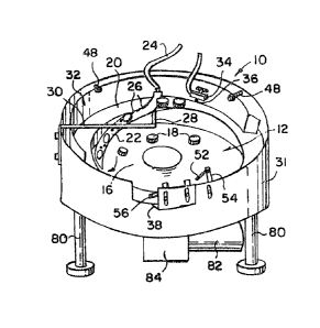
throughout the several views, figures 1 through 4 illustrate a
rotary feeder 10 that includes a rouncl bowl 12, spinning
clockwise on a vertically mounted shaft 14. The bottom of the
bowl is a domed floor 16 such that articles, in this case
bottle caps 18, when dumped into the bowl, slide to the
outside perimeter of the bowl. The caps 18 are dumped into
the center of the rotating bowl 12 from a cap supply hopper
(not shown) above the :Eeeder 10. The caps 18 will be
delivered to the bowl 12 on demand only and this will be
determined by a switch (not shown) that is inserted into the
bowl and is physically or photo electrically in contact with
-the caps being oriented. Once the caps are in the inside of
the bowl 12 they will be Eorced by centrifugal force, back
pressure, and gravity to the outside perimeter of the bowl.
Figure 1 shows how the caps 18 are forced onto an upper
ledge 20 of the bowl 12 by sliding up an inclined s-tationary
ramp 22 approxima-tely five or six inches to the upper ledge.
The ramp 22 is a tube or can be a flat plane 22a as sen in
figure 5. Attached to the top of -the ramp is an air line 24.
~ 3 1 ~037
The air escapes through a series of air jets 26 which are
arranged in a spiral fashion such that the caps 18 are pushed
up the ramp so that the cups are flipped over allowing for the
majority of the caps to be in the good open side up position.
The ramp 22 has a mounting pos-t 28 attached to a ramp support
bracket 30 which goes half way across the upper end of a
stationary housing 31. Support bracket 30 is bolted to side
of housing 31 by two bolts for rigidity.
There is an adjustable guide ring 32 around
approximately half of the perimeter of the upper ledge 20 of
the rotary bowl 12 such that the cap diameters can be
presented to lay flatly on the upper ledge and is supported by
only one or two screws 48 for easy adjustment. This guide
ring 32 serves only as a leaning wall and has no mechanical
function other than to keep the caps in a single file and to
be adjusted depending upon cap diameters. The drive shaft 14
is driven by a variable D.C. motor 82 and gear box 84. This
variable speed input is used for diEferent stylings of caps
such that each style of cap has its optimum performance speed.
Cap discrimination is assisted with the use of a
proximity switch 34 which is mounted on the guide ring 32 just
above the caps being oriented. This proximi-ty swi-tch 34
senses the caps 18 as to whether they are open side up or open
side down. If the cap is open side up, it will be sensed by
the proximity switch 34 as a good cap and it will be allowed
to pass without being rejected. IE, however, the cap is open
side down when it passes under the proximity switch, it will
be sensed as a bad cap and a momentary air burst from an air
1 ~ ~ 2037
jet 36 located below the proximity switch 34 will reject the
cap by pushing it back into the bowl 12~ These good caps on
the upper ledge 20 will then proceed in a clockwise direction,
until they are discharged from an exit ramp 38 where they will
be used for a future process (see Figure 3).
Figure 5 shows a first modified rotary feeder 10a. The
caps 18 are dumped into the center of a bowl 12a in the same
manner as in feeder 10. the caps are spun to the outside edge
of the clockwise rotating bowl and are facilitated by a domed
floor 16a which helps to push them to the edge. Once they are
at the periphery of the bowl, they are pushed up the ramp 22a.
the ramps 22 and 22a both have ingers 40 which fit into
grooves 42 on the domed floors 16 and 16a; so as to give a
continuous smooth surface for the caps to climb up the ramp.
The ramp 22a like 22, is supported by a ramp support
bracket 30a, and does not rotate with the bowl but is rather
fixed to a stationary housing 31a of the feeder 10a. The ramp
22a can be changed in varying widths to accommodate wider or
narrower caps. The bracket 30a is only a partial bracket as
shown in figure 5 and allows for ample clearance for the caps
18 being dumped in. Once the caps are sent up the ramp 22a
the top of the ramp has a slight twist that will push and turn
the caps onto an upper ledge 20a and can ei-ther use air assist
as in ramp 22 or only by back pressure from -the other caps in
the feeder pushing up the ramp. They move from the ramp along
the upper ledge to an ad]ustable wiper bar 44 where all the
stacked up caps are pushed bac~ into the bowl with only one
level of caps permitted to pass the point of the wiper bar 44.
1 3 1 2037
From here, -they continue to a spring steel ledge width
selector 46 which is adjusted with a screw 48a. It is made of
a spring steel metal so that when the adjusting screw 48a for
the ledge width selector is turned, it will increase or
decrease the width of the upper ledge 20a the cap 18 is riding
on. An adjustmen~ can be made from a 13mm diameter cap to a
70mm diameter cap or more depending on the width oE the upper
ledge 20a. The width of this ledge is important because at
the point of where the adjusting screw 48a for the ledge width
selector is, the caps are selected. This selection is
accomplished in several ways that will be discussed later.
In addition, the spring steel ledge width selector 46 is
inserted at two points 50, 50 through the housing 31a of the
feeder lOa which keeps the spring steel ledge width selector
46 levels flat and at a positive position at all times. After
the caps have been selected at or about point "X" only the
caps that are open side up still remain on the upper ledge 20a
with the caps continuing in a clockwise fashion to an
adjustable exit wiper 520 This wiper is made adjustable by a
support bracket 54 mounted on the housing 31a of the feeder
lOa. Its function is to push the cap 18 tha-t is now hanging
over the edge of the upper ledge 20a of the bowl 12a back
against the housing 31a of the feeder lOa so that it may exit
on an exit ramp 38a, while at the same time being ~uided by a
discharge bracket assembly 56.
The majority of flat cap styles are preferably selected
for by the use of a single air jet 58 placed over the point
"X" so that all selections of upside down or open side up caps
--7--
~ 31 2037
is done at or near point "X". This air jet 58 is mounted on a
slotted bracket 60 and can be adjusted both horizontally and
vertically by the bracket. It is adjusted sideways by
actually directing the air jet 58 onto the cap. The principle
of how the air jet works is simple. Once the cap 18 is
positioned on the upper ledge 20a so that it is hanging over
the upper ledge, the air jet 5~ will actually push the open
side up cap against the outside wall of the spring steel ledge
width selector ~6 and prevents it from falling back into the
bowl 12a. However, if the cap is upside down, the same air
jet 58 will work in a different fashion. It will actually
push down on the edge of the cap 18 that is closest to the
center of the bowl which will cause it to fall back into the
bowl. Once they have passed the air jet 58 only the open side
up caps 18 will remain and be discharged in the fashion
described earlier. In addition, the pressure of air applied
to this cap is critical and needs to be adjusted depending
upon the weight and size of the cap. This air pressure is
adjusted with the use of a simple valve 58a.
In cases not shown where the caps are not flat, two of
these air jets 58 are used side by side. The first air jet is
used to reject the caps that are laying on their side and
these caps are pushed by air and roll off the upper ledge 20a
and pushed back into the bowl 12a. After the first air jet,
only the caps that will remain are the caps that are open side
up or open side down, and these caps will be selected for the
same as a typical ~lat cap described above.
1312037
In figure 6 the selection is done at point "X" by using
both an air jet 62 and a photo electric sensor 64. The sensor
64 is mounted on the spring steel width selector 46 directly
above the cap. The air jet 62 is placed behind the spring
steel ledge width selector 46 being directed through a hole in
the spring steel width selector. There the proximity switch
sensor 64 will determine if the cap is open side up or open
side down. If it is open side up, the sensor 64 will allow
for the cap 18 to pass by and not switch on the air jet 62 as
shown in figure 7. However, if the cap is open side down once
it is under the sensor, the air jet 62 will ba activated and
will push the cap to be rejected back into the bowl 12a.
This rejection can be accomplished by air physically
pushing the cap 18 back into the bowl 12a or by a small piston
of an ejector solenoid (not shown~ pushing the cap back into
the bowl, since both work satisfactorily. The schematic
drawing for this control is shown in detail in figure 7.
Amplifier 66 is set on low ampliEication for dark-on
operation. When the sensor 64 does not "see" the cap 18, the
amplifier 66 will activate the air jet 62 of ejector solenoid
by a switch 67. A time delay relay 68 can be added to shut
off the air jet or ejector solenoid when no cap is detected
after a predetermined amount of time. The distance between
the top of the cap 18 and the sensor 64 should be one half to
one inch. The lower -the profile of the cap, the closer the
sensor should be with decreased sensitivity. A 80ma
transistor output 70 could be used in place of the relay 68 to
control the air jet or ejector solenoid for longer operating
1312~37
life. The replacement of the electronic sensor 64 with a
pneumatic sensor (not shown) may also be used with equal
success.
Figure 5 shown that for a flat cap 18 one air jet 58 can
be used to discriminate open side up and open side down caps.
For a cap that is either tall or "square" -two air jets 58, 58
side by side will be required as mentioned earlier.
"square" cap is one where the diameter and the width are
identical or nearly identical, and therefore, both good open
side up, bad open side down and caps on their sides will be
kept on the ledge 20a after passing adjustable wiper bar 44.
The above system of discrimination cannot be applied to
certain caps 18a that have a spout, snip top, push-pull or any ~-
other protrusion, as shown in figure 9. In figure 8 these
caps 18a are oriented such that they hang from two rings 72
and 74. Again, they are dumped into the center of the bowl
12a as any other type of cap. They are pushed up the ramp 22a
and lay on these rings 72 and 74. These two rings are
installed by screws 76 into the feeder 10a described earlier,
and can be removed when standard caps are to be oriented.
Once the caps 18a are laying be-tween the inner and outer rings
72 and 74, they will not fall out, thus they pendulate between
the rings. A rejecting wiper 78 will push them off, and back
into the bowl before exiting, if the~ are not pendulating
(hanging protrusion pointed down).
In addition, the entire feeder 10 or 10a rests on four
adjustable support legs 80. The bowls 12 and 12a are driven
by 1/4 HP D.C. motor 82 with an electronic variable speed
--10--
~IZ037
controller (not shown) reduced with a right angle reducer
(gear box) 84. The need for any pulleys, sprockets, belts or
chains are not required. By turning a knob tnot shown) on the
controller, the rpm's of the feeder 10 and lOa will increase
and decrease. For most applications the speed is not very
critical, but generally the greater the rpmls of the bowl 12a,
the faster the caps 18a will be oriented and discharged.
In addition so that the rotary feeder may run
continuously even when caps or parts are not required to be
discharged due to an excess of parts being oriented, an air
jet can be successfully mounted on the housing 31a just prior
to the adjustable exit wiper 52. The air jet is operated by a
solenoid switch, such as those manufactured by ASCO, that will
upon receiving a signal from an electric eye mounted in a
discharge chute tnot shown) cause a blast of air to push all
caps about to exit back into the feeder bowl 12a. When the
discharge chute, after the exit of the caps, is again open the
electric eye will then shut off the air jet and allow for more
caps to be discharged.
While certain novel features of this invention have been
shown and described and are pointed out in the annexed claims,
it will be understood that various omissions, substitutions
and changes in the forms and details of the device illustrated
and in its operation can be made by those skilled in the art
without departing from the spirit of the invention.