Note: Descriptions are shown in the official language in which they were submitted.
~L 3 ~
COMBINATION STORAGE CONTAINRR AND TRIPLE SEAL LID
Field oE the Invention
This invention relates generally to containers and lids
thereore, and more particularly to containers with lids Eor
hermetically sealing foodstuffs or other perishable goods
therein.
~ackground of the Invention
Various containers and covers for hermetically sealing
foodstuffs are disclosed in the patent literature and many are
commercially available. Such containers and their covers are
typically made o~ plastic, such as polypropylene, polyethylene or
other locally deformable, yet resilient compositions.
While prior art containers and their lids have proved
generally suitable for their intended purposes, such devices may
develop leaks or weak seals between the lid and the container as
a result of misalignment or misfitting of the cover and con-
tainer. Moreover even when the lid is aligned and properly
Eitted on the cover, air or liquid leakage can still occur
through the seal between the lid and container.
Objects of the Invention
It is therefore the object of this invention to overcome
the disadvantages of prior art containers and covers therefore.
It is still a further obiect of the instant invention to
provide a container and lid thereore which includes multiple
seals to insure that a good air or liquid-tight seal is maintain-
ed between the lid and the containerO
It is still a further object of the instant invention to
provide a container and a lid which is relatively simple in
construction and can be manufactured inexpensivel~, yet which
provides a secure seal therebetween.
Summar~ of the Invention
These and other objects of the instant invention are
achieved by providing the combination of a plastic container and
lid. The combination is arranged to store food or other air
perishable goods therein. The container comprises a body having
a side wall defining a mouth to the interior oE the container and
having a rim extending about the periphery thereof. The rim
~ 3 ~
-- 2 --
includes an outwardly extending portion terminating in a downward-
ly extending flange. The container has a firs-t surface formed by
a portion of the inner surface oE its side wall, a second surface
ormed by a portion oE the top surEace of its outwardly extending
rim portion and a third surface formed by a portion of the outer
surface of the rim's flange. The lid comprises a central portion
and a peripheral sealing portion. The peripheral portion has a
bottom surface which defines a second surface of the lid, a
downwardly projecting flange extending about the periphery of the
lid and having an inner surface defining a first surEace of the
lid, and a downwardly projecting rib spaced inwardly from the
flange and having an outer surface defining a third surface of
the lid. The first, second and third surfaces of the lid form an
annular space therebetween. The lid is arranged to be releasably
secured to the container with the lid's rim disposed within the
annular space. The first, second and third sur-Eaces of the lid
and container are configured and sized so that the rim is tightly
received within the annular space with the first, second and
third surfaces of the lid tightly engaging the first, second and
third surfaces, respectively, of the container to create
respective first, second and third, liquid--tight seals.
Description of the Drawings
Other objects and many of the attendant advantages of
this invention will be readily appreciated as the same becomes
better understood by reference to the following detailed descrip-
tion when considered in connection with the accornpanying drawings
wherein:
Fig. 1 is a top plan view of -the combination container
and lid embodying the invention;
Fig. 2 is an enlarged sectional view taken along line
2-2 of Fig. l;
Fig. 3 is an exploded sectional view of the portions of
the container and lid shown in Fig. 2 but prior to their secure-
ment to each other.
Detailed Description_of_the Preferred Embodiment
Referring now to various Eigures of the drawing wherein
like reference characters re~er to like parts, a combination
JJ ~
-- 3 --
container and lid embodying the invention is shown generally at
20 in Fig. 1. The combination basically comprises a container 22
and a lid 24. It should be noted that the combination 20 shown
in Fig. 1 and embodying the invention i5 of a flat oval shape,
but the principal of this invention applies as well to other
shapes of containers and lids therefore, such as rectangular,
square, circular, etc.
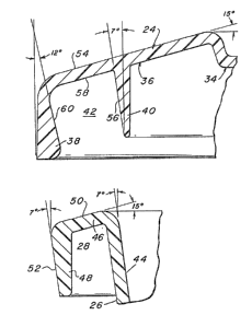
As seen clearly in Fig. 2 the container 22 basically
comprises a hollow body formed by a sidewall structure, generally
identified by the reference numeral 26, and a bottom wall (not
shown). The bottom wall is positioned at the lower end oE the
sidewall 26 and serves as the support surace of the container.
A sealing rim or lip 28 extends about the periphery of the top of
the sidewall and defines within its boundary an open end or mouth
30 of the container 22. The mouth provides access to the hollow
interior 32 of the container 22. The details of the sealing rim
28 will be described later. Suffice it for now to state that the
rim is adapted to be received within an annular space, to be
described later, in the lid to form three good hermetic and/or
liquid-tight seals therebetween. In accordance with the
preferred embodiment of the invention each of the seals extends
about the entire periphery of the junction between the lid and
container.
Access to the interior 32 of the container is provided
via the open mouth 30 of the container 22 when the lid 24 is
removed. The lid 24 is of the same general overall shape as the
container 22 and includes a generally planar cen~ral portion 34
(Fig. 3) and sealing means 36 extending about the periphery of
the central portion. The sealing means 36 will be described in
considerable detail later. Suffice it for now to state that the
sealing means 36 includes a downwardly projecting flange 38
extending about the entire periphery of the lid 24. An annular
rib 40 also projects downward from the underside of the lid and
is spaced inward from the Elange 38. The space between the
flange 38 and the rib 40 defines an annular recess 42 (Fig. 3)
which is adapted to tightly receive the container's rim 28
therein when the lid is in place.
13~2~
In accordance with a preferred embodiment of the inven-
tion the container is formed of any suitable plastic material,
such as polypropylene. The cover or lid 24 is also formed of any
suitable plastic material which is somewhat deformable, yet resil-
ient, such as a medium density polyethylene.
Referring now to Figs. 2 and 3, the details of the rim
28 will now be described. As can be seen therein the upper end
of the container's sidewall 26 is flared slightly outward so that
in its inner surface 44 extends at a slight acute angle, e.g., 7
to the vertical. The upper portion of surface 44 forms a first
engagement surface oE the rim. The rim 28 also includes an out-
wardly extending portion 46 and terminates in a downwardly extend-
ing flange portion 48. The top surface S0 of portion 46 is
conical and extends at a slight acute angle, e.g, lS, down from
the horizontal. This top surface forms a second engagement sur-
face of the rim. The flange 48 includes an outer surface 52
which also extends at a slight acute angle, e.g., 7 from the
vertical and hence is at the same angle as surEace 44. The outer
surface 52 forms a third engagement surface of the rim. The
three engagement surfaces 44, 50 and 52 are arranged to cooperate
with three corresponding surfaces, to be described later, on ~he
underside of the lid at its sealing means 36.
Referring n~w to Fig. 3 the details of the sealing means
36 will now be described. As can be seen the sealing means 36
includes a generally planar top surface 54 which extends downward
at a slight acute angle, e.g., 15, from the horizontal when the
lid is horizon-tal. The lid's rib 40 includes an outer surface 56
which extends at a srnall acute angle, e.g., 7, to the vertical
when the lid is disposed horizontally. This outer sureace forms
a first enyagement surface of the lid. The underside oE sealing
means 36 is in the form of a generally conical surface with the
portion thereoE between the rib 56 and the flange 38 defining a
lower surface 58. rrhe lower surface 58 forms a second engagement
surEace of the lid. The flange 38 flares in cross section Erom
its upper end to its lower or free end so that its inner surface
60 extends at a small acute angle, e.g., 12, to the vertical.
~ 3 ~
-- 5 --
This inner surface 60 forrns a third engagement surface of the
lid. The surfaces 56, 58 and 60 define therebetween the
heretofore identified annular recess 42.
The securement of the lid 24 to the container 22 to seal
foodstuffs or other products within -the container and out of
con-tact with the ambient air is effected as follows: the lid is
placed over the container so that the rim 28 is generally aligned
with the annular recess 42. The lid is then pushed downward,
whereupon the li~'s flange 38 engages the radiused corner forming
the interface of the rim's surfaces 50 and 52. This action
causes the flange to pivot slightly outward to slide downward on
outer surface 52. Accordingly, the angle that the flange's inner
surface 58 makes with the vertical is now the same as the angle
of rim surface 52, i.e., approximately equal to 7~, from its
previous 1~ inclination. At the same time rim surface 56 slides
along surface 44. This action enables the rim to be slid
completely into the recess 42. The natural bias of the flange
38, and the bias of the rib 40 cooperate with each other on the
abuting surfaces of the container's rim to automatically draw the
rim 28 as deeply as possible into the recess. This action insures
that the inner surface 44 of the sidewall of the container intim-
ately engages the outer surface 56 of the rib in a first fluid-
tight seal 62 (Fig. 2), the top surface 50 of the rim 28 intim-
ately engages the undersurface 58 of the lid in a second fluid-
tight seal 64 (Fig~ 2) and the outer surface 52 of the rim's
flange ~8 intimately engages the inner surface 60 of the lid's
Elange 38 in a third fluid-tight seal 66 (Fig. 2).
In order to facilitate the removal of the lid 24 from
the container 22, the lid includes a tab 68 projecting from one
end thereof. This tab provides a place for one to grip the lid
to pull it off the container.
As can be seen in Fig. 1 the container 22 also includes
a pair of projecting handles 70, one at each end of the contain-
er. The handles 70 serve as means to enable the container to be
readily transported.
Without further elaboration the foregoing wiLl so fully
illustrate our invention that others may, by applying current or
future knowledge, adopt the same for use under various conditions
of service.