Note: Descriptions are shown in the official language in which they were submitted.
- "
~312~2~
TRACTION CONTROL SYSTEM FOR CONTROLLING
SLIP OF A DRIVING WHEEL OF A VEHICLE
-:~f~ o ~ r~ v~ /N
The present invention relates to a slip rate control
device for a vehicle, and more particularlyl to a slip rate
control device for controlling a driving wheel during the
starting or acceleration of the vehicle.
In general, when the traction force of a driving
wheel exceeds the friction force between the wheel and a road
surface [(the coefficient of friction between a wheel and a
road surface)x(load on a driving wheel by the vehicular weight
(vehicular load))] during starting or acceleration of the
vehicle, the driving wheel slips. When it is assumed that the
circumferential speed of the driving wheel is Vw and the
vehicular speed is V, the slip rate which indicates the de~ree
of slippage, can be obtained from the following equation:
l5 ~ = (Vw-V)/Vw -- (I)
:
Depending on this slip rate 1, the friction force
between the wheel and the road surface (that is, the critical
value of the trac-tion force of the driving wheel) varies as
shown in Fig. 4. The friction force represented on the
vertical;axis reaches its maximum value at a predetermined
value ~ 0. Here, the friction force between the wheel and the
road surface, indicated by the solid curve, is in the
travelling direction (longitudinal direction) of the vehicle,
~3~ 2~
1 but the friction force in the transverse direction (lateral
force) falls as the slip rate A gets larger, as indicated by
the dotted curve in the drawing.
sased on the above consideration, in order to
maximize the driving efficiency of the vehicle by maximi~ing
the fxiction force in the longitudinal direction between the
wheel and the road surface and also to prevent the sideslip of
the vehicle by suppressing to the utmost the reduction of the
friction force in the transverse direction between the wheel
and the road surface, a method is known in which the slip
rate A is detected and controlled so that it will be close to
the predetermined value ~OO More specifically, for example, a
lower limit value A 1 and an upper limit value A z of a
predetermined range including said predetermined value A 0 are
set for the slip rate ~ in accordance with t.he vehicular speed
V. Then, the circumferential speed Vw of th.e driving wheel is
controlled by controlling a torque control ~.nit according to
the value of the slip rate ~ obtained ~rom t.he driving wheel
speed Vw and the vehicular speed V, thereby performing feedback
control of the slip rate ~ o~ the driving wh.eel so that it
falls within the above predetermined range ~1 ~ 2-
However, when the gear ratio of the transmission ischanged, even if the vehicular speed is not changed, the
driving force o~ the driving wheel is changed, thus the
vaxi~tion width and the variation rate (variation quantity) o~
the slip rate ~ , which are control parameters, are also
varied~ For example, the variation width and the variation
rate c~ the slip rate ~ become larger when the gear of the
transmission is set low than those when the gear is set high,
~3~ ~29
1 thus causing a problem in that the control accuracy of the slip
rate ~ is diminished.
SUMMARY OF_THE_INVENTION
In order to eliminate above described disadvantage,
an object of the present invention is to provide a slip rate
control device for a vehicle, wherein, even if the variation
width and the variation rate of the slip rate ~ of the driving
wheel, which values are generated during starting or
acceleration of a high horse power vehicle or at the time of
starting or acceleration of a vehicle on a slippery road
surface, are varied by the change of the gear ratio of the
transmission, highly accurate control is still performed.
Therefore, maximum friction force is generated between the road
surface and the wheel so that the reduction in the lateral
force generated by the wheel is minimized, as well as improving
the driving efficiency of the vehicle.
In order to overcome the above and other
disadvantages, the instant invention is directed to a control
system for controlling the slip of a driving wheel of a
vehicle. The control system comprises a driving wheel speed
sensor means for sensing the speed of a driving wheel and for
generating a driving wheel speed signal as a func-tion thereof,
and a vehicle speed sensor means for sensing the speed of the
vehicle and for generating a vehicle speed signal as a function
~5 thereof. A slip rate calculation means is coupled to the
driving wheel sensor means and the vehicle speed sensor means
for calculating a slip rate of the driving wheel with respec-t
to the vehicle movement. Also~ a differentiating means is
coupled to the slip rate calcula-ting means, for calcula-ting the
2 ~
l differential value of the slip rate, and a setting circuit
means is provided for generating a first predetermined
differential slip rate value, and a second predetermined
differential slip rate value wherein the second predetermined
differential slip rate value is greater than said first
predetermined di~ferential slip rate value. A first comparison
means is operativel~ coupled to the differentiating means and
the setting circuit means, for comparing the differential value
of the slip rate with the second predetermined differential
slip rate value and outputting a first exce,s slip slgnal when
the differential value of the slip rate is greater than the
second predetermined differential slip rate value~ Further, a
second comparison means is operatively coup.led to the -
differentiating means and the setting circuit means, for
comparing the differential value of the slip xate with the
: first predetermined slip rate diEferential value and outputting
a first slip signal when the differential v~lue of the slip
rate :is greater than the firs-t predetermined slip rate
differential value. A first generating means is operatively
coupled to the vehicle speed sensor means for generating a
first xeference value as a function of the vehicle speed, and a
third comparison means is coupled to the first generating means -
and the drivin~ wheel speed sensor means, for comparing the
first re~erence value with the driving wheel speed signal and
outputting a second slip s.ignal when the driving wheel speed
signal is greater than the first reference value.
Additionally, a second generating means is operatively coupled
to the vehicle speed sensor means for generating a second
reference value as a function of vehicle speedr and a fourth
comparison means is operatively coupled to the driving wheel
~ \ ~
13~ 2.9
1 speed sensor means and the second generating means for
comparing the driving wheel speed signal with said second
reference value and outputting a third slip signal when the
driving wheel speed signal is greater than the second reference
value. Furthermore, an output means is coupled to the first,
second, third and fourth comparison means/ for providing a
driving wheel slip control signal when at least one of
(i) the first comparison means outputs the
first excess slip signal;
(ii) both the second and third comparison
means output the first and second slip
signals; and
(iii) the fourth comparison means outpu-ts the
third slip signal.
BRIEF DESCRIPTION OF THE DRA~INGS
The advantages of the invention will become apparent
in the following description taken in conjunction with the
drawings, wherein:
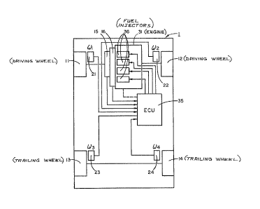
Figure 1 is a schematic diagram of a vehicle with a
control system according to the instant invention,
Figure 2 is a schematic diagram of a fuel supply
control unit for supplying fuel to the engine of the vehicle~
Figure 3 is a schematic diagram of a logic circuit of
the ECU of Fig. 2;
~- 25 Figure 4 is a graph showing the traction force
between a wheel and road surface versus the slip rate;
Figure 5 is a graph showing the trailing wheel speed
versus the driving wheel speed;
~ 3 ~
1 Figure 6A is a graph showing the values of the
driving wheel speed signal superposed above a graph showing the
differential slip rate as a function of time;
Figure 6B is a graph of the slip rate ~ as a
function of time as used in an alternate embodiment of the
instant invention;
Figure 7 is a schematic diagram of the above
alternate embodiment of the ECU of Fig> 2 and as illustrated in
Fig. 6; and
Figure 8 is a graph showing the trailing wheel speed
versus the slip rate for the alternate embodiment of Fig. 7;
Figure 9 is a schematic diagram illustrating a third
embodiment of the ECU of Fig. 2; and
Figure 10 is a schematic diagram ;llustrating a
fourth embodiment of the ECU of Fig. 2.
DETAILED_DESCRIPTION OF THE PREFERRED EMBODIMENT
Referring to Fig. 1, a vehicle 1 is provided with a
slip rate control device according to the instant invention.
The vehicle 1 is, for example, a front wheel drive -type vehicle
with front wheels 11 and 12 as driving wheels which are driven
by an engine 31, and rear wheels 13 and 14 are trailing wheels.
The instant invention i5 also applicable to a vehicle having
rear wheel drive in a similar manner as described below.
Further, the instant invention could similarly be applied to a
four wheel drive vehicle. Therefore, for the purposes of this
application, trailing wheels are considered to be non-driving
wheels. In other words, in a front wheel drive car, the
tra:iling wheels would be -the rear wheels, while in a rear wheel
drive car, the trailing wheels (non-driving wheels) would be
1 the front wheels. Driving wheels 11 and 12 and trailing wheels
13 and 14 are provided wi-th driving wheel speed sensors Zl and
22 and trailing wheel speed sensors 23 and 24, respectively.
The left and right driving wheel speeds l and ~2 are detected
by driving wheel speed sensors 21 and 22, and left and right
trailing wheel speeds ~3 and ~4 are datected by trailing wheel
speed sensors 23 and 24. The detection signals are input to
ECU (Electronic Control Unit) 35. In ECU 35, the larger of the
driving wheel speeds ~1 and ~2 is selected as the driving wheel
speed Vw in equation I above and the average value (ID3 + ~4~/2
of the trailing wheel speeds ~,3 and ~4 is ca]culated and used
as the vehicular speed V in equation I above. The slip rate
(1) is thus calculated in the following equat:ion:
(~1 or ~2¦ _~2 ~ _ _ .. (II)
1 2
In this case, "~1 or ~2" rneans to c;elect only the
larger of the two wheel speeds. Furthermore,- the differential
value (or rate) A of the slip rate A is also determined by ECU
35~
In addition, a clutch 15 and a transmission 16 are
interposed-between engine 31 and the driving wheels 11 and 12.
Clutch 15 and transmission 16 are equipped with sensors ~not
shown) which transmit clutch signals and transmission signals,
respectively, to ECU 35. In ECU 35,.when the clutch signal
indicates that clutch 15 is engaged, the torque of driving
wheels 11 and 1.2 is controlled by controlling a fuel supply
control unit (described below~ thereby controlling the slip
rate ~ of driving wheels 11 and 12. (See equation II above.)
The slip rate ~ is thus reduced by controlling the torque to
2 9
l the driving wheels. The example of Figs. 1 and 2 control
torque by cutting off fuel supply to the engine or more
specifically to individual cylinders. Such a process
reduces torque to the driving wheels, thus reducing ~ 1
and ~ 2 of the driving wheels, which in turn reduces the
slip rate A , and enables the driving wheels to regain
traction with respect to the road.
It should be noted that other methods of reducing
torque to the driving wheels may also be employed in the
instant invention. For example, the torque applied to the
driving wheels may be reduced by cuttiny ignition to the
engine or by applying brakes to the driving wheels, indivi-
dually or as a pair. In Fig. 2 the fuel supply control unit
is shown operating on a four cylinder internal combustion
engine 31, as an example. Of course, the system would be
operable on any type of engine. An intake manifold 32 is
connected to engine 31 to provide an intake passage thereto.
A throttle valve 33' is disposed inside of throttle body 33
which is positioned in intake manifold 32. Adjacent to
throttle valve 33' is a throttle valve opening
( ~ th) sensor 34 which converts the opening of throttle
valve 33' into an electrical signal and transmits the signal
to ECU 3~.
A fuel injection valve (or fuel injector) 36 is
positioned between engine 31 and throttle body 33 in the
intake manifold 32. A fuel injection valve 36 is positioned
slightly upstream of the intake valve (or valves) of each
cylinder. The fuel injection valve 36 is connected to a
fuel pump and fuel
-
2 ~ ~ ~
1 source (not shown) in a conventional manner. Fuel injection
valve 36 is electrically connected to ECU 35 as well, and the
valve opening time of fuel in~ection valve 36 is con-trolled by
a signal from ECU 35. Thus, to cu~ the fuel supply to a
cylinder, for example, the corresponding fuel injector would
xeceive a signal (or lack of signal) from ECU 35 causiny that
injector not to supply fuel to the cylinder.
An absolute pressure (PB~) sensor 38 is disposed at
the end of pipe 37 which communicates with the intake manifold
32 at a point downstream of throttle valve 331 and upstream of
fuel injector 36. An absolute pressure signal, converted into
an electrical signal by ab~olute pressure sensor 38, is
transmitted to ECU 35.
An engine cooling wàter temperature sensor
(hereinafter referred to as "Tw sensor") 39 is disposed on
engine 31 to monitor the temperature of the engine cooling
water. The Tw sensor 39 consists of a thermistor (or like
device) mounted in the circumferential wall of the engine
cylinder which i5 filled with cooling water and applies the
detected water temperature signal to ECU 35 An engine speed
sensor (hereinafter referred to as "Ne sensor") 40 is connected
to a crankshaft or camshaft (not shown) of the engine. The Ne
sensor 40 outputs a crank angle position signal (hereinafter
referred to as "TDC (top dead center) signal") at a
25 predetermined crank angle position for every 180 rotation of
the crankshaft of the engine, i~e. in this example with a four
; cylinder engine, Ne sensor 40 outputs a TDC signal at a crank
angle position before a predetermined angle relating to top
dead center (TDC3 at the beginning of the intake stroke for
30 each cylinder, and this TDC signal is transmitted to ECU 35.
~ 2~ ~
1 A three way catalytic converter 42 is disposed in
exhaust pipe 41 and performs the purging of HC, CO and NOx
components in the exhaust gas. On the upstream side of
catalytic converter 42, an 2 sensor 43 is disposed in exhaust
pipe 41. Sensor 43 detects the concentration of oxygen in the
exhaust gas and transmits an 2 concentration signal to ECU 35.
Furthermore, driving wheel speed sensors 21 and 22,
and trailing wheel speed sensors 23 and 24 are connected to ECU
35. ~n auxiliary parameter sensor 44 is provided to input to
ECU 35, and may be used for detecting other engine parameters.
ECU 35 lncludes an input circuit 35a for shaping the
input signal waveforms from various sensors (including from
driving wheel speed sensors 21 and 22, trailing wheel speed
sensors 23 and 24, the sensor o~ clutch 15 and the sensor of
! 15 transmission 16), to correct the voltage level to a
predetermined level, to convert an analog signal value to a
digital signal value and so forth. ECU 35 also includes a
central processing unit (hereinafter referred to as "CPU") 35b,
memory means 35c storing various operational programs which are
executed in CPU 35b and operational results therefrom, etc.,
and an output circuit 35d which outputs a driving signal to
fuel injection valve 36, and so forth.
For example, whenever the TDC signal is inpu-t to ECU
35, the CPU 35b calculates the fuel injection time Tout for
fuel injection valve 36 from the following equation based on
engine parameter signals from the above various sensors which
are ~ed through the input circuit 35a
Tout = Ti x Gl + G2 ... ~III)
Jl C3 1 ~o 1 h ~J
1 whexein Ti is a basic value of the injection time of the
fuel injection valve 36 and is determined in accordance with
engine speed Ne and absolute pressure PBA in the intake
manifold. G1 and G2 are a correction coefficient and a
correction variable which are calculated from predetermined
arithmetic expressions such that various characteristics
such as starting characteristics, exhaust gas
characteristics, and acceleration characteristics may be
opti-mized corresponding to the driving condition of the
engine as detected by the above sensors. Then, CPU 35b
through output circuit 35d feeds a driving signal to fuel
injection valve 36 to open valve 36 for a time Tout as set
forth above. For example, in order to cut fuel to a
cylinder, the driving signal from CPU 35b would simply be
inhibited.
Fig. 3 is a schematic diagram of a circuit showing
the configuration of the principal part of CPU 35b of Fig.
2. In Fig. 3, selection circuit 51 (also known as the Hi-
Select circuit) receives driving wheel speed signal inputs
from driving wheel speed sensors 21 and 22 which represent
~1 and ~2~ respectively. Selection circuit 51 then selects
the larger value (Vw) of the two detected driving wheel
speeds ~1 and w2. A vehicular speed arithmetic circuit 52
receives inputs from trailing wheel sensors 23 and 24
(representing ~3 and W4 respectively) and calculates the
average value V = ~3 + ~4)/2 as the vehicular speed V based
on the trailing wheel speed ~3 and ~ 4. It is also
contemplated that the vehicular speed may be detected by
other means. For example, the vehicular speed V might be
11
- - \
1 determined based on the phase relationship between an output
wave of an ultra sonic device and a sensed reflection wave
from the road.
The circuit of Fig. 3 can be divided into three
operational portions, the excessive A- portion (where A- is
the differen$ial value of the slip rate ~ ), the prediction
control portion, and the excessive A portion (where ~ is the
slip rate as indicated above in aquations I or II). Output6
from selection circuit 51 and arithmetic circuit 52 are
applied to a slip rate calculating circuit 53. The slip
rate calculating circuit 53 calculates the slip rate ~ based
on equation I or II set forth above. The output of slip
rate calculating circuit 53 is then input to differentiating
circuit 54. The differentiating circuit 54 calculates the
differential value A- of the slip rate.
The excessive A- portion of the circuit is
illustrated when an output of the differentiating circuit 54
is applied to the excessive A~ decision circuit (or first
comparison circuit) 55. A predetermined value setting
circuit 60 provides predetermined values which are used as
reference or comparison values. The predetermined value
setting circuit 60 provides a value ~- 2 ~i.e., a
predetermined differential slip rate value~ to the minus
input of the excessive A- decision circuit 55. The output
of circuit 55 is then appliPd to OR gate 56. The output of
OR gate 56 is input to AND gate 57. The other input to AND
gate 57 is connected to the sensor of clutch 15. The output
of AND gate 57 provides a slip control signal to control the
51ip of the driving wheels by reducing torque, by cutting
12
~ 3 ~
1 off the fuel supply, by cutting off the ignition, or by
applying braking force, or by any other method used for
controlling the slip of the driving wheels.
The prediction control portion of the circuit of
Fig. 3 includes first prediction control decision circuit
(or second comparison means) 58 and second prediction
control decision circuit (or third comparison means) 63.
The outputs of the comparison circuits 58 and 63 are applied
to AND gate 59 and the output of AND gate 59 is applied to
OR gate 56. Specifically, the positive input of the second
comparison circuit 58 receives the output of differentiating
circuit 54. The negative input of second comparison circuit
58 is xeceived from setting circuit 60. Setting circuit 60
provides a ~ 1 value (a predetermined differential slip
rate) to the negative input of the second comparison circuit
58.
The positive input of third comparison circuit 63
is received from the output of selection circuit 51. The
minus input of third comparison circuit 63 is received from
a first speed arithmetic circuit (or first generating
circuit) 61. The first generating circuit 61 calculates a
reference value VR1 based on constant values K1 (where K1 >
C1) and Cl, which cons~ant values are received from setting
circuit 60 and the vehicle velocity which velocity is
received from vehicular speed arithmetic circuit 52.
The excessive ~ portion of the circuit includes
an excessive ~ decision circuit (or fourth comparison
means) 64. The output of fourth comparison circuit 64 is
also applied to OR gate 56. The positive input of fourth
13
, "
~ 3 ~
1 comparison circuit 64 is provided from the output of
selection circuit 51. The negative input of fourth
comparison circuit 64 is received from a second speed
arithmetic circuit (or second generating circuit) 62. The
second generating circuit 62 calculates a reference value
VR2 based on predetermined constant values K2 and C2 and the
vehicle velocity. The vehicle velocity is received from
vehicular speed arithmetic circuit 52, while the constants
K2 and C2 are received from setting circuit 60. The
predetermined values set in setting circuit 60 depend on the
specific vehicle using the instant traction control
system. The predetermined values set in the setting circuit
60 are generally determined by emperical studies. Also, an
input from
13a
1 the transmission may be supplied to setting circuit 60 so that
the predetermined values may also depend upon the gear ratio of
the transmission.
The operation of Figs. 1 and 2 and the circuit of
Fig. 3 will be described below.
Specifically, with reference to Figs. 1 and 2, ECU 35
sets a lower limit value ~1 and upper limit value A2 in a
predetermiend range, including the predetermined value Ao
(shown in Fig. 4) as the reference value for slip rate control
determined for the slip rate Ao in accordance with the
gear ratio determined by the transmission signal. Further,
the ECU sets first and second reference values ~1 and A~2
(A'2 greater than A'l) for slip rate variation control for
the differential A'of the slip rate in accordance with
the gear ratio, the control delay from the operation command
; to a fuel supply control unit (until the device starts
operation practically), and the above said predetermined
value Ao for slip rate control. Thereby the above
; describedfuel supply control unit is controlled in
accordance with the difference between either one of the
driving wheel speed signal wl or w2, and the reference
values VRl and VR2 corresponding to Al and A2
respectively. The difference between the
differential A~ of the slip rate and the first and second
reference values A~l and Aq2 is described in detail below.
- 14 -
2 ~ ~ ~
I In other words, ECU 35 controls the fuel supply control unit in
accordance with the control rules (i) - (iii) as follows:
(i) If ~ > ~ 1 and ~ > ~ 1~ control of
the system is effec-ted so tha-t A is reduced,
for example~ the fuel is cut tprediction
control).
(ii) If A > ~ 2~ control of the system
is effected so that A is reduced, for example,
the fuel is cut (prevention oi. excessive slip
rate ~ )-
(iii) If A ~ ~ 2~ control of the system is
effected so that ~ is reduced, for exa-mple,
the fuel is cut (prevention oi- excessive
differential sl.ip rate A ).
5~ The reason the differential~rate (variation of slip
rate) ~ is used in addition to the slip rate ~ in order to
control the 51ip rate A as shown in abovesa d control rules
(i) thru (iii), is that, since it is predicted that the slip
rate ~ comes off the predetermined range ~ 2 in case the
differential slip rate ~ is large even if the slip rate ~ is
within the predetermined range A 1 ~ ~, improvement of the
response characteristic of the control of the slip rate A is
accomplished by performing prediction control, etc as set
forth above.
Specifically with regard to Fig. 3, driving wheel
speed signals ~1 and ~2 are obtained from driving wheel speed
sensors 21 and 22, respectively. The selection circuit 51 tor
Hi-Select circuit) then outputs a signal based on the higher of
the values ~1 and ~2. Also, as set forth above, the vehicular
speed arithmetic circuit 52 calculates the vehicle speed V
~ 3~ 2~
l based on the average value of the two trailing wheel speed
signals from the trailing wheel speed sensors 23 and 24.
Then, the output signals from selection circuit 51 and
arithmetic circuit 52 are received by slip rate calculating
circuit 53. The slip rate calculating circuit 53 calculates
the slip rate ~ based on equation II set forth above. The
differentiating circuit 54 receives the output of the slip
rate calculating circuit 53 and calculates the differential
value ~- of the slip rate. The predetermined value setting
circuit 60 sets lower limit speed value coefficient K1 and
constant C1, upper limit speed value coefficient K2 and
constant C2, and first and second differential slip rate
reference values A 1 and ~ 2 based on the gear ratio,
respectively. Further, the above first and second reference
values A 1 and ~ 2 are set after correction corresponding
to above described control delay of the fuel supply control
unit and the lower limit and upper limit values A 1 and A 2
When the excessive A decision circuit (or first
comparison circuit) 55, determines that the differential
value A of the slip rate is larger than the second refer-
ence value A 2 by comparing the output signal fromdifferentiating circuit 54 with the output signal represent-
ing the second reference value A ~ (~rom ~he setting
circuit 60), the comparison circuit 55 outputs a high level
signal (hereinafter referred to as "HI signal't~ to an AND
gate 57 through an OR gate 56, and in other cases, outputs a
low level signal (hereinafter referred to as 'ILO signal").
Further, when clutch 15 has been engaged, and the
engine and the driving wheels have been coupled with each
1~
~ 3 ~
l other, a sensor provided on clutch 15 outputs a HI signal
directly to AND gate 57. When the HI signal is input from both
the OR gate 56 and the sensor on clutch 15, AND gate 57 outputs
a fuel cut signal which inhibits the output of the fuel
injection time T out which would normally inject fuel during
the time T out from fuel injection valve 36, thus valve 36
remains closed thereby reducing the torque of driving wheels 11
and 12. Thus, when the differential value A- of the slip rate
is larger than the second reference value A'2, i.e.
when the differential slip rate ~' is getting larger sharply,
the differential slip rate A' is controlled so that it gets
smaller (i.e., the prevention of excessive slip rate speed).
First prediction control decision circuit (or
second comparison circuit) 5~3 outputs a HI signal to AND gate
59 when it determines that the differential value A-
of the slip rate is larger than the first reference value A-l.
Otherwise, second comparison circuit 58 outputs a LO signal.
Additionally, a first speed arithmetic circuit (or first
generating circuit) 61 calculates a reference value VRl based
on a correction coefficient Kl and a correction constant C
which are stored in setting circuit 60, which may be a ROM
(Read Only Memory) associated with ECU 35. Values Kl and C
may be selected as a function of the gear ratio. First
- generating circuit 61 then calculates the first predetermined
speed reference value VRl from the following equation:
VRl = KlV + Cl .... (IV)
- 17 -
1 Here, a value which satisfies the equation
A 1 ~ (VR1 - V)/VRl is set for constants K1 and Cl. The
second prediction control decision circult (or third comparison
circuit) 53 Otltputs a HI signal to ~ND gate 5g when it
determines that the driving wheel speed Vw is larger than the
first predetermined speed reference value VRl by comparing the
output signal from selection circuit 51 with the output signal
from the first speed arithmetic circuit (or first generating
circuit) 61. In o-ther conditions, third comparison circuit 63
outputs a LO signal. When a HI signal is .input from both the
first and second prediction control decision circuits 58 and
63/ AND gate 59 also outputs a HI signal to OR gate 56. Then,
as previously described, OR gate 56 outputs a ~II siynal to AND
gate 57, and if the clutch 15 is engaged, AND gate 57 outputs
the fuel cut signal, and thus the fuel cut is accomplished. As
a result, it is presumed that the slip rate A is coming off
~he predetermined range A 1 ~ ~ 2 and gettir,g larger
gradually when (the slip x:ate A )>(the lower limit value
A 1) and (the differential value ~o of the slip rate)>(the
20 first reference value A 1) However, in such a case, the
torque of driving wheels 11 and 12 is reduced and the slip rate
is controlled so that it gets smaller, thereby preventing the
slip rate ~ from becoming excessive (thus prediction control
is achieved).
Furthermore, second speed arithmetic circuit (or
second generating circuit) 62 calculates a second reference
value VR2 based upon a correction coefficient K2 and a
correction variable C2 which are s-tored in setting circuit 60.
Circuit 62 also receives vehicle speed V, from the vehicular
30 speed arithmetic circuit 52. It then calculates the second
18
~3~ 2~
l predetermined speed value VR2 from Kl, Cl, and vehicular speed
V from the following equation, wherein constants ~2 and C2 are
se-t in the same manner as Kl and Cl:
VR2 = K2V ~ C2 . . . (V~
r
The excessive ~ decision circui-t (or fourth
comparison circuit) 64 outputs a HI signal to AND gate 57
through OR gate 56 when it de-termines that the driving wheel
speed Vw from the selection circuit 51 is larger than the
second predetermined reference value VR2 fron the second speed
arithmetic circuit 62 by comparing the two values. Then, as
previously describedr AND gate 57 outputs a iuel cut signal if
the clu-tch 15 is engaged, and thus the fuel cut function is
performed. As a result, when the slip rate ~ is larger than
the second predetermined value ~ 2~ i.e., when the slip rate
~ is excessive, the slip rate is controlled so that it is
reduced (thus, prevention of excessive slip rate is achieved).
In abovementioned method, for pred:iction control of
the slip rate A , excessive slip rate prevention control, and
excessive differential slip rate prevention control based on
control rules (i) - (iii~ described above, the reference range
~ 1 ~ A 2 may be regulated in accordance with the gear ratio
of transmission 16, and at the same time, the first and second
reference values ~ 1 and ~ ~ related to the
differential slip rate ~ may also be regulated in accordance
with the gear ratio of the transmission 16. Accordingly, even
if the variation width and the variation rate of the slip rate
~ , which are control parameters, are changed by the change of
the driving force of the driving wheel due to the change of the
~ 3 ~ ~ ~ 2 ~
1 gear ra-tio of the transmission 16, control of the slip factor
~ is performed as set forth above no matter what the
transmission gear ra-tio is.
Since the control of the slip rate is prevented when
clutch 15 is completely disengaged (-through AND circuit 57) a
problem does not arise wherein clutch 15 is not engaged and
useless slip rate control is performed notwithstanding the fact
that no driving force is being applied -to the driving wheels 11
and 12. Nor does a problem arise wherein the fuel cut signal
is output by control runaway, etc~, resulting in engine 31
stalling, notwithstanding the fact that clutch 15 has been
disengaged completely and the engine speed has been reduced.
Further, it is preferable that computed values are
read out of a V - VRl table and a V VR2 table which are
;~.15 s-tored in advance in memory means35c instead of calcul~ting
first and second predetermined values VRl and VR2 by
multiplication and addition by the firs-t and ~econd speed
arithmetic circuits 61 and 62 based on equations IV and V
everytime the control is performed. This reduces the
~rocessin~ time, which improves the response charac-teristic of
the slip rate control.
Fig. 5 is a graph of the driving wheel speed (~D)
versus the trailing wheel speed (~T) Line A indicates the
-condition where there i5 no slip. In other words, line A shows
the condition where the driving wheel speed is equal to the
trailing wheel speed:
D T ... 'VI)
13~2 ~ 29
1 Line B illustrates a theoretical condition for predicting slip
where:
D T ~ ..~ (VII)
This is derived from equation II which ca~ be summarized as:
~1 ~ D ...................... (VIII3
1 - Al = T ... (IX)
D
D T(l _~ ) ... (VII)
However, reference values from the first and second generating
circuits 61 and 62 are determined in accordance with lines C
10 and D, respectively. Line C represents equation IV:
VRl = KlV + Cl (IV)
Wherein, Cl, as set forth above, is selected in order to
overcome practical difficulties in actually detecting slip at
low speeds. Kl is selected so that line C intPrsects
15 theoretical line B at a predetermined speed. Line C, which
approximates theoretical line B at higher speeds, is therefore
used to produce the reference value VRlO Line D is also
determined similarly to line C and is used to produce the
reference value VR2, which would approximate a theoretical
20 value of ~D as a function of ~T as indicated by line E. Thus,
~2 ~ 2~
1 as shown, line D represents equation V:
VR2 = K2V + C2 ~V)
Fig. 6 is a graph of the driving wheel speed ~ D
as a function of time. Time t is indicated on the
horizontal axis and the driving wheel speed w D is indicated
on the vertical axis. The solid curve actually relates to
the speed of the driving whPel w D. The dotted line relates
to the speed of the vehicle or trailing wheel speed w T~
lo Re~erence values VR1 and VR2 are indicated as diagonal
lines. Reference value VR1 is shown by the single dot line
; and reference value VR2 is shown by the double dot line.
These lines represent the same lines in Fig. 5. Below the
graph of the driving wheel speed is a graph of the
lS differential slip rate A with respect to time. These two
graphs are combined into 6A since they both operate to
generate a driving wheel slip control signal which will
control the torque of the engine. Further, below the graph
of the differential slip rate in Fig. 6A is a graph of the
fuel cut (P/C) signal in an on or off state. The dotted
line between fuel cut signal graph and the two graphs above
it are for reference to indicate which events in the two
upper graphs cause the fuel cut signal to turn on or turn
of~.
For example, in the top graph of Figure 6A, the
excess ~ portions are indicated by arrows 72, 74, and 76.
This is where the driving wheel speed w D is greater than
the second re~erence value VR2. At the points represented
, .
. . ,
2 ~
1 by arrows 72, 74, and 76, the excess A circuit becomes
operative and comparator 64 is turned on and thus outputs a
HI signal.
Below the top graph of Fig. 6A, the solid arrows
78, 80, and 82 represent the position where the driving
wheel speed ~D is greater than first reference value VR1.
This is used in the prediction control circuit. In other
words, when considered in conjunction with Fig~ 3, arrows
78, 80, and 82 represent the time when comparator 63 turns
on and outputs a HI signal. However, this is only one half
of the prediction control circuit. Because the output of
comparator 63 is input to an AND gate 59, simply the turning
on of comparator 63 will not cause the output of a driving
wheel slip control signal to reduce torque to the driving
wheel.
Therefore, the second part of the prediction
control circuit must also be turned on in order to provide a
driving wheel slip control signal. In considering the
second graph of Fig. 6A which shows the differential slip
rate A with respect to time, it should be noted that
predetermined differential slip rate values A 1 and ~ 2 are
indicated on the vertical axis. Solid arrows 84, 86, and 88
represent the points where the value of the differential
slip rate ~ is greater than the predetermined differential
slip rate value ~ 1 In other words, arrows 84, 86, and 88
represent the points where comparator 58 turns on because
the value of the differential slip rate is greater than the
predetermined slip rate value A 1. As with the other half
of the prediction control circuit (comparator 63) discussed
~3
1 above, simply the turning on of comparator 58 will not cause
the output of a driving wheel slip control signal to reduce
the torgue to the driving wheels. Therefore, because
comparator 58 is input to AND gate 59, both comparators 58
and 63 must be on in order for a prediction control signal
to be issued and thus have the driving wheel slip control
signal be issued. Solid arrows 90, 92, and 94 represent the
time periods in which the turning on of comparators 58 and
63 overlap, thus causing AND gate 59 to turn on and issue a
driving wheel slip control signal. Thus both the signals
from the driving wheel speed graph and the differential slip
rate graph are combined to result in the output of the
prediction control circuit.
Arrows 96 and 98 represent the points where the
differential slip rate A is greater than the predetermined
differential slip rate value A 2. It is at the points of
arrows 96 and 98 where the comparator 55 of the excessive A
circuit turns on because the differential value of the slip
rate from differentiating circuit 54 is greater than the
predetermined differential slip rate value A 2 from setting
circuit 60. At this point, comparator 55 outputs a high
level which causes the output of a driving wheel slip
control signal. Thus, arrows 96 and 98 illustrate the
operate of the excessive A control circuit.
The fuel cut signal is shown below the upper two
graphs and represents the time when a fuel cut siqnal i5
turned on and off. In other words, when the fuel cut signal
is on, the ECU inhibits the opening of fuel injector valve
36. When the fuel cut signal is off, the ECU is allowed to
24
1 transmit the injection time signals to open and close the
fuel injector 36 in accordance with usual engine
operation. Specifically, at reference numeral 100 the fuel
cut signal is turned on by comparator 55 which is
represented by arrow 96 on the differential slip rate
graph. The fuel cut signal is maintained in the on state by
prediction control circuit AND gate 59 which is represented
by arrow 90 which indicates the on state of AND gate 59.
Further, the excess A circuit, or
24a
,
1 comparator 64, maintains the fuel cut signal in the on state as
illustrated by arrow 72. When the comparator 64 turns off (at
the end of arrow 72) the fuel cut signal is turned off at
reference numeral 102. The fuel cut signal remains off until
reference numeral 104 indicates that it is turned on by the
excessive ~ circuit represented by arrow 98. This, of courser
corresponds to the turning on of comparator 55. ~s with the
previous fuel cut signal in the on s-ta-te, the operation of
prediction control circuit (AND yate 59) is indicated by arrow
92 and the operation of the excess A circuit (comparator 64)
is indicated by arrow 74. The fuel cut signal is then turned
off when the comparator 64 of the excess ~ circuit is turned
off as illustrated at the end of arrow 74. Once again, the
fuel cut signal is turned on at reference 1~8. Howe~er, in
this case, the prediction control circuit (;~ND gate 59) turns
on as indicated by arrow 94. The excess ~ circuit (comparator
64) turns on as represented by arrow 76 and maintains the fuel
cut signal in the on state. The graph does not show when the
fuel cut signal is turned off.
Fig. 6B is directed to an alternate embodiment of the
invention, which is described below. ThereEore, Fig. 6B will
be described in detail below.
Furthermore, since the average value of the speed of
the trailing wheels 13 and 14 is considered to be vehicular
speed V in the above method, and right and left in-ternal wheel
speed differences generally cancel out one another when the
vehicle turns, i.e. less error is produced in detecting the
vehicular speed V regardless of whether the vehicle is making a
right turn or a left turn. Thus, the slip rate control may be
performed with a high degree of accuracy. In addition, since a
-
- ~ 3~ 2~
Select system has been adop-ted (see selection circuit 51,
above) in which the larger value between the speed of right and
left driving wheels 11 and 12 is selec-ted for the driving wheel
speed Vw, the driving force is controlled by the wheel with the
smaller slip rate, i.e. the friction coefficient between the
road surface and the wheel. In this case, since a diferential
gear apparatus interposed between right ancl left driving wheels
11 and 12 in ordinary systems, neither driving wheel 11 or 12
is controlled beyond the fric-tion force o~ the driving wheel
~or which the driving force has been select:ed in all the cases
of straight running or turning. As a result, the driving
wheels on both sides will not slip at the same time, compared
with a LOW-Select system in which the smaller value is selected
between the speed of right and left driving wheels, thus making
it possible to perform sufficient slip rate control. Further,
! the lowering of the lateral force which can be generated by the
wheel adoption of a HI~Select system may be made small for both
driving wheels.
Additionally, in the above embod ment, a fuel supply
control unit is used as the driving wheel lorque control unit
and the driving torque of the driving whee s 11 and 12 is
reduced by cutting the supply of fuel at a predetermined time
by said fuel supply control unit. However, other methods-may -
be employed so that the torque of the driving wheels 11 and 12
may be reduced by having the ignition delayed by an ignition
timing unit. Also, as stated above, the torque to the driving
wheels, may be reduced by applying brakes to one or both of the
driving wheels.
Therefore, as described above, a slip rate control
device according to the instant invention, has a driving wheel
26
l speed sensor detecting the speed of a driving wheel or wheels,
a trailing wheel speed sensor detec-ting the speed of a trailing
wheel or wheels, a slip rate calculating means for calculating
the slip rate of the driving wheel based on said detec-ted
driving wheel speed and trailing wheel speed. Further the
control device has a driving wheel torque control unit for
controlling the torque of the driving wheel based on said
computed slip rate~ A predetermined value setting circuit
means is provided for generating a reference value of said slip
rate in accordance with a gear ratio of a t:ransmission of the
vehicle, wherein said driving wheel torque control unit reduces
the torque of said driving wheel when said computed slip rate
exceeds the abo~e slip rate reference value. Alsor a
differential slip rate compu-ting means (or diffexentiating
circuit) is provided for computing the differential (or rate)
of the slip rate of the above driving whee:l, and a differential
slip rate reference value setting means pxovides a reference
value of the diEferential of said slip rate in accordance with
the gear ration of the transmission of the vehicle, wherein the
driving torque control unit reduces the to:-que of said driving
wheel when the computed differential of the slip rate exceeds
the differential rate reference value.
Thus, control of high precision may be achieved even
if the varia-tion width and the variation rate of the slip rate
of the driving wheel produced at the time of starting or
acceleration in a large horse power vehicle or at the time of
starting or acceleration in a vehicle on a slippery road
surface may change due to the change of the gear ratio of the
transmission, thus resulting in maintenance of maximum friction
force between the road surface and-wheel. Accordingly, the
27
- ~ 3 ~
l driving efficiency of the vehicle may be improved and the
decrease in lateral force produced by a wheel may be minimized
(in o-ther words, the lateral traction of the wheel will be
enhanced).
Fig. 7 illustrates an alternate embodiment of the
circuit of CPU 35b shown in Fig. 2. Specifically, in the
alternate embodiment of Fig. 7, the prediction control portion
and the excessive 1 portion oE the circuit compare the slip
rate ~ (calculated in the slip rate calculating circuit 53)
with calculated, reference values, rather than comparing -the
driving wheel speed with calculated reference value~ as in Fig.
3.
With regard to the prediction control portion of the
circuit, the inputs to the firs-t prediction control decision
circuit (or second comparison circuit) 58 are the same as in
Fig. 3. However, the inputs to the second prediction control
decision circuit (or third comparison circuit) 63 have been
altered. More specifically, the positive inpu-t to comparator
63 receives the slip rate A from slip rate calculating circuit
53 rather than a driving wheel speed signal from selection
c.ircuit 51.
The negative input of comparator 63 continues to
receive the output from first generating circuit 61. HoweverJ
the reference value generated by circuit 61 is different than
in the embodiment of Fig. 3. Specifically, first generating
circuit 61 cont.inues to receive the outputs of setting circuit
60, which include values Kl and Cl. The reEerence value A Rl
generated by circuit 61 is determined in accordance with the
following equation:
28
ARl = 1 Kl + Cl -- (X)
v
where V is the vehicular speed de-termined by arithmetic circuit
52~ Equation X above is derived from the basic equation
for A :
A= D wl, ........................ ..(XI)
. ~D
.
Then, assuming that ~ D' the actual detected driving wheel
speed, is equal to VRl, the reference speed value, then
equation IV can be written as follows:
.
~ = KlV ~ Cl ... ~XII)
10 Thus subs-tituting equation XII for ~D and yehicular speed V for
~T~ equation XI may be written as follows:
- 1 _ V ... (XIII)
Rl K V -~ C
which results in equation X:
-- (X)
ARl Kl + Cl
V
Therefore, the output of circuit 61, determined as se-t forth
above, is used as a reference value for the negative input of
comparator 63. Fig. 8 tdescribed below) represents the value
of A in a graph.
Rl
With regard -to the excessive A portion of the
?O circuit, the positive input to the excessive A decision circuit
(or fourth comparison circuit) 64 is received Erom slip rate
1 3 ~ 2 ~
. calcul.a-ting circuit 53, rather than from selection circuit 51.
In other words, the slip rate A is provided to thP positive
inpu-t of comparator 64 rather than the driving wheel speed
being provided to comparator 64.
The negative input of comparator 64 is still received
,, from second generating circuit 62. However, as with first
generating circuit 61'(described above), in this alternate
embodiment, the reference value generated by circuit 62 is
different from that ofAthe circuit of Fig. 3. Specifically,
circui`t 62 generates a reference value A R2 which is applied
to the negative inpu-t of comparator 64~ Reference value A R2
is determined according to the following equation:
~ - 1 ... (XIV)
R2 K2 ~ C2
where K2 and C2 are values supplied from setting circuit 60,
.15 and V is the vehicular speed. The value :eor A R2 is derived
in the same manner as the value for A Rl explained above.
Fig. 8 is a graph illustrating lhe trailing w~eel
speed ~T versus the slip rate A . The trailing wheel speed ~T
is represented on the horizontal axis and the slip rate A is
represented on the vertical axis. The first reference value
~ Rl from the first generating circuit 61 is determined
according to equation X and is illustrated by curve C' in Fig.
8. Accordingly, the second reference value A R2 from second
generating circuit 62'is determined. according,to equation XIV
and is illustrated by curve D' in Fig. 8.
Fig. 6s shows the alternate embodiment (as
illustrated in Fig. 7) wherein the slip rate 1 is shown as a
function of time t. The reference values A Rl and A R2 are
2 ~ 2 ~
1 similarly illustrated as in Fig. 8. Fig. 6B may be compared
with the differential slip rate graph of Fig. 6A above since
FigsO 6A and 6B are aligned with one another. When, in Fig.
6B, A is greater than ~ R2 as shown at reference numerals
112 and 114, then comparator 64 of Fig. 7 is turned on to
activate the excessive 1 circuit and a driving wheel slip
control signal is issued. When 1 is greater than 1 Rl as sho~n
at reference numerals 116, 118 and 120 and labeled as PC lcomp
63~, then comparator 63 of Fig. 7 is turned on to activa-te
one-half of the prediction control circuit. Arrows 116, 118
and 120 of Fig. 6B may be compared with arrows 8~, 86 and 88 of
Fig. 6A to determined whether or not the prediction control
cixcuit will be activated.
Figs. 9 and 10 are third and fourth embodiments of
the circuit of CPU 35b. Basically, Fig. 3 represents the first
embodiment, and Fig. 7 represents the second embodiment of the
invention. In Fig. 7, the prediction control circui~
(comparator 63~ and excessive ~ circui-t (comparator 64) use
the slip rate to compare with reference values rather than
comparing the driving wheel speed signal with reference values.
Figs. 9 and 10 are embodiments which are found somewhere in
between Figs. 3 and 7.
For example, in Fig. 9, comparator 63 of the
prediction control circuit receives its positive input from
selection circuit 51, as in Fig. 3. The minus input of
comparator 63 receives the reference value VRl from first
generating circuit 61, also as in Fig. 3. However, comparator
64 of the excessive 1 circuit receives its positive input from
the slip rate calculating circuit 53, and its nega-tive input
from second generating circuit 62'. Further, circuit 62
-" ~ 3 ~ 9
1 provides the reference value ~ R2 to comparator 64 as in the
embodiment of Fig. 7.
Wi~h regard to Fig. 10, comparator 63 of the
predic-tion con-trol circui-t receives its positive input from
slip rate calculating circuit 53, as in Fig. 7. The minus
input of comparator 63 receives a reference value A Rl from
,` first genera-ting circuit 61~, also as in Fig. 7. How~ver,
comparator 64 of the excessive A circuit receives its positive
input from selection circui~ 51, and it6 negative input from
second generating circuit 62. The reference value pxovided
from circuit 62 to comparator 64 is V~2, as in the embodiment
of Fig. 3. Otherwise, Figs. 9 and 10 are similar to Figs. 3
and 7.
Although a specific form of embodiment of the instant
invention has been described above and ilLustrated in the
accompanying drawings in order to be more clearly understood,
the above description is made by way of e:~ample and not as a
limitation to the scope of the instant invention. It is
con-templated that various modifications apparent t.o one of
ordinary skill in the art could be made without departing from
the scope of the invention which is to be determined by the
following Claims.
32