Note: Descriptions are shown in the official language in which they were submitted.
~ 3 1 2 ~
The present invention relates to a mounting apparatus for
supporting optical equipment, such as night vision goggles, on
the head of a person in a manner which permits firm support and
ready adjustment.
There are numerous optical devices in use for which it is
desirable for the user to have it supported in his line of vision
without having to hold the device. Night vision goggles which
are used by the military are such devices which clearly must be
mounted so as to permit the user to have his hands free. Because
such goggles are used by persons having a wide variety of
physical characteristics, any mounting apparatus for them must
permit a wide range of adjustments with respect to the position-
ing of the goggles in a direction perpendicular to the viewer's
line of vision and also longitudinally, i.e., on an axis parallel
to the line of vision. Even when the same person is mounting and
dismounting optical equipment frequently, it is necessary to be
able to readily adjust the position of the equipment each time it
is mounted for a number of reasons, such as the fact that the
head support assembly to which the equipment is attached may not
always be positioned in exactly the same manner.
Moreover, in order to permit the wearer to assume a number
of positions, such as a Iying position, while viewing through the
equipment, it is preferable to also be able to selectively adjust
the angle of the line of viewing through the goggles with respect
to what is the normal line of vision of the wearer. It Is
important when the mounting device is being used under conditions
to which the military is exposed that the device can not only be
easily attached to a head support apparatus but that it can be
adjusted in both of the above indicated directions by using one
hand, preferable by the same hand by which the optical device has
been grasped for the initial mounting on the head support
apparatus. The above are characteristics which have not been
general present in mounting devices now in use.
~ 3 ~
-- 2
Also, under certain conditions of use, such as in combat,
the mounting device, the head support apparatus and the manner in
which the mounting device is mounted on the heat support ap-
paratus must be extremely dependable so not permit the goggles to
become readily detached or dislocated if subjected to relative
severe shock because an unexpected loss of the device at a
critical moment could put the wearer at a disadvantage or cause
injury to him. Again, known equipment have not fully achieved
reliability or sufficient durability while still providing the
necessary adjustment features. Not only is durability in the
mounting device necessary, but it is clear that the reliability
of the optical device is no better -than the dependability of the
head support apparatus, the function of which to hold the
mounting device in place.
It is an object of the present invention to provide a
durable mounting arrangement which permits easy mounting and
adjustment of optical equipment.
According to one aspect of the present invention, there is
provided a mounting device for adjustably positioning optical
equipment on a viewer's head, the mounting device being mountable
on a head support assembly worn by the viewer, and including a
housing with first guide means disposed between the housing and a
mounting means connectable to the head support assembly for
permitting movement of the housing relative to the head support
assembly along a substantially vertical axis extending normal to
the viewer's normal line of vision. A base rneans is provided
which has attachment means for connecting the optical equipment
thereto. A second guide means is disposed between the base means
and the housing for permitting movement of the base means
relative to the housing along a horizontal axis extending
substantially parallel to the line of vision. Locking means is
associated with each guide means for independently preventing the
relative movement in each guide means, and a manually operable
unlocking member is mounted in the housing and is movable from a
1 3 ~
- 3 -
locking position to unlocking positions for selectively
actuating each of the locking means to effect unlocking of
the locking means.
According to another aspect of the invention, there
is provided a mounting device, which is mountable on a
head support assembly worn by a viewer, and permits
adjustable positioning of optical equipment on the
viewer's head in front of his line of vision. The
mounting device includes a pair of guide means, each
having a slide member and track means for permitting
relative back and forward movement of the slide along a
single axis in the direction of the longitudinal axis of
the track member. A housing member and a base means are
provided, the base means having attachment means for
connection to the optical equipment. One of the guide
means is disposed between the housing member and the head
support assembly and the other is disposed between the
housing member and the base member. ~ne of the guide
means is oriented to permit relative movement on a
vertical axi~ normal to the line of vision of the viewer,
and the other is oriented to permit relative movement on a
horizontal axis parallel to the line of vision. A
releasible lock means is associated with each guide means
for preventing the relative movement in the guide means so
that on release of the lock means, the level of the
optical equipment and the distance of the optical
equipment in front of the viewer may be selectively
adjusted.
The accompanying drawings show, as an example, one
embodiment of the invention, and wherein:
Figure 1 is a side view of a mounting device in a
mounted condition on a head support assembly according to
the present invention;
1 5
Figure 2 is an enlarged side view of the mounting
device shown in Figure 1;
Figure 3 is an enlarged perspective view of the
mounting device as shown in Figure 2;
Figure 4 is an enlarged front view of the mounting
device as shown in Figure 2;
Figure 5 is a sectional view of the mounting device
as seen from the line 5--5 of Figure 5;
Figure 6 is a cross sectional view as seen from line
6--6 of Figure 5 showing a pin and track arrangement as
used in a guide means of the mounting device of Figure 2;
Figure 7 is an exploded perspective view of the head
support assembly of Figure 1;
Figure 8 is a view of the components used in
fabricating a head piece which is one of the parts of the
head support assembly of Figure 8; and
Figure 9, which appears on the same sheet as Figure
7, is a cross sectional view through the head piece as
seen from line 9--9 of Figure 7.
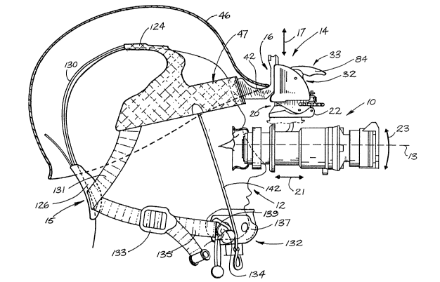
In Figure 1, the reference character 10 denotes
optical equipment, such as night goggles, mounted in a
position in front of the normal line of vision 13 of a
person, hereinafter termed the wearer 12. The optical
equipment 10 is supported in the position by a mounting
device 14 carried on the front of a head support assembly
15 worn by the wearer 12. As will be described
131?J41
-- 5
in more detail below, the head support assembly 15 is fixed
firmly to the head of the wearer, and once adjusted, the mounting
device 14, which is detachably affixed to a front portion of the
head support assembly 15, holds the optical equipment against
relat~ve mo~eme~t with respect to the head support assembly, and
thus, the wearer's head. However, the mounting device 14
includes a first guide means 16 which allows adjustment of the
optical equipment 10 in an up and down direction, or what is
normally the vertical direction. This direction, as indicated by
the arrow 17, is, therefore, perpendicular to the line of vision
13. There is further provided a second guide means 20 which
permits adjustment of the optical equipment 10 in a back and
forth or longitudinal direction, i.e, in a direction parallel to
the normal line of vision 13, as denoted by the arrow 21, this
direction being perpendicular to the direction permitted by the
guide means 16, and is, therefore, a direction which is normally
horizontal. An adjustment means 22 is also provided for the
purpose of allowing tilt or angular adjustment, in an up and down
direction in a vertical plane, i.e., about a horizontal
transverse axis, which is an axis provided by a pin 19, which is
perpendicular to the line of vision 13. Adjustment of the means
22 moves the optical equipment in the direction indicated by
curved arrow 23.
The mounting device 14 includes a housing 24, which may be a
cast or molded member having a vertical tracl< 25 formed in rear
side thereof and horizontal track 26 formed in a lower side
thereof. The tracks 25 and 26 are separated from a hollow
interior of the housing 24 by vertical back wall 27 and horizon-
tal bottom wall 28, respectively, ~Figure 3). Extending forward
from back wall 27 and upwardly from bottom wall 28 is a pair of
spaced side walls 30, 30 having curved front edges 31, 31, which,
in the main, are arcuate, extending from the top of the back wall
to the front of the bottom wall. Contained in a hollow space 32
provided between the side walls 31, 31 is a~ locking means 33 for
the guide means 16 and 20 which will be described in more detail
below.
The guide means 16 and 20 are similar in structure, each
including their respective tracks 25 and 26, which receive
slide members 35 and 36, respectively. The slide member of each
of the guide means is restricted to sliding movement in the
direction of the longitudinal axis of the track. In the case of
guide means 16, the slide member 35 is the member which is
normally stationary, at least relative to the head of the wearer,
and the track 25 moves relative to the slide member 35 during the
mounting and adjustment operation, but in any event, as will
become more apparent below, it is the selective relative movement
between the slide member 35 and the track 25 which accomplishes
the adjustment of the optical equipment 10 in the direction of
arrow 17 shown in Figure 1 and the selective relative movement
between the slide member 36 and the track 26 which accomplishes
the adjustment of the optical equipment in the direction of arrow
21.
The vertical track 25 of the guide means 16 is in the form
of a rear facing channel defined by the rear surface 38 of the
back wall 27 and a pair of rearwardly directed flanges 39, 39.
The opposed side surfaces 40, 40 provided by the flanges 39, 39
inside the channel of track 25 are V-shaped providing surfaces
40a and 40b, as best seen in Figure 6. The side slide member 35
of the guide means 16 has a main slide portion 41 and rearwardly
projecting mounting legs 42 by which the slide member 35 is
attached to the head support assembly 15. The forward ends of
legs 42 are integrally formed with a body portion 43 of the slide
member which connects at the front therewith to a pair of slide
raiJs 44, 44 separated by an elongated slot 48. The mounting
legs 42, the body portion 43 and rails 44, 44 are preferably a
single integral unit which may be molded, for example from a
tough durable plastic, such as NYLON.
The side rails 44, 44 have longi~udinally extending V-shaped
~3~2~1~
side edges 45, 45, each defined by surfaces 45a and 45b and being
shaped to be closely received in the V-shaped side wall 40 of the
track so that the movement of the slide member relative to the
track 25 is limited to a direction corresponding to the lon-
gitudinal axis of the track.
The slide member 35 may be permanently affixed to the head
support assembly to facilitate mounting and dismounting of the
mounting device on the head support assembly which would be worn
continuously by the wearer, such as under a helmet shown at 46 in
Figure 1, at a time when it is expected that the optical equip-
ment, such as night goggles, may be needed at any moment. More
specifically, the slide member 35 may be permanently affixed to a
head piece 47 of the head support assembly, the rear ends of
mounting legs being secured to a flat front surface 50 of the
head piece 47 at the very front thereof by fastening means 51,
such as screw, which are threaded into the mounting legs 42
(Figure 2). The mounting legs 42 may be of sufficient length so
that the main slide portion 41 is held in a vertical orientation
in front of the helmet, as shown in Figure 1.
~s is most apparent in Figure 3, the upper ends of the V-
shaped side edges of the side rails of the slide member have
upper portions 52 which curve smoothly inward toward each other
so as to provide a rounded upper end to the side rails. Thus,
when it is wished to install the optical equipment, the mounting
device 14, which carries the optical equipment, is grasped by one
hand of the wearer and the track 25 is slid down over the slide
member 35, the rounded portion at the upper end of the side rails
assisting in guiding the upper end of the side rails into the
channel of the track 35. Once mounted, it can be seen that the
30 movement of slide member 35 in track 25 of guide means 16 permits
vertical movement of the housing 24 relative to the head support
assembly 15 and thus to the head of the wearer.
The structure of the guide means 20 is similar to that of
` 13~ 2~1~
guide means 16 except that it need not be constructed to permit
ready assembly and disassembly because the mounting device and
the optical equipment carried thereby are usually kept as a
unit for mounting on the head support assembly as described
above. The housing 24 has a downwardly open channel providing
track 26, the track being formed by the lower surface 5~ of the
bottom wall 28 and downwardly projecting side flanges 55, 55.
The opposing opposed inner surfaces 56 of the flanges 55 are
V-shaped. The slide member 36 is mounted for sliding movement
in the direction of the longitudinal axis of the horizontal
track 26 formed by the downwardly open channel, the side edge
surfaces 57 of the slide also being V-shaped to complement the
shape of the V-shaped surfaces 56 of the flanges 55, 55. The
slide member 36, like the slide member 35 includes two
longitudinally extending slide rails 60, 60 separated by a
central slot 61, and it further has downwardly projecting
flanges 62 formed integrally with the rails and between which
is mounted a base member 63. The base member has a lower
surface 65 against which the optical device lO is secured by
fastening means 64 which may be screws which pass through
openings in the base member and are threaded into openings in
the optical equipment.
The base member 63 is connected to the flanges 62 by
previously mentioned pin 19 which allows base member 63 to
pivot about a horizontal transverse axis relative to the
housing 2~. At the front of the base member 63 there is
provided a bore 66 extending through the base ~ember. Also
extending upwardly into the base member 63 is a counter bore 67
which is coaxial with the bore 66 so as to provide a shoulder
68. A screw means for adjusting the tilt of the optical
equipment includes an externally threaded, elongated shaft 70
which extends through the bore 66 and is threaded through an
internally threaded ~ember 71 fixed to the rails 60, 60 of the
slide member 36 thereabove. The threaded shaft has fixed
thereto a knurled wheel 72 which may be turned by the thumb or
a finger of the wear~r so as to rotate the shaft 70 in either
direction and thereby adjust the amount the shaft is
1 3 ~
threaded through the internally threaded member 71. The lower
end of the threaded shaft is provided with a head 73 which bears
against the shoulder 68. A coil spring 74, which encircles the
pin 19, and has outer ends 74a and 74b, one each engaging the
slide member 36 and the base member 63, respectively, for biasing
the base member 63 in a clock-wise direction as viewed in Figure
6 so that the shoulder 68 is held against the head 73 and there
is, therefore, no slack movement of the base member about the pin
19 and relative to the slide member. It can be seen that by
tilting the optical equipment, a more convenient angle can be
obtained when the wearer is in a prone position, and in fact
allows the wearer to maintaining a more concealed position.
Locking means 33 includes individual locking devices 76 and
77 for each of the two guide means 16 and 20, respectively,
consisting of like parts. Referring particularly to locking
device 76, as shown in Figures 2, 5 and 6, it may be seen that
there is provided a pin 80 which has an elongated shank 81 which
projects through an opening 82 ~Figure 6) in rear wall 27 of
housing 24 and through slot 48 between side rails 44, 44. The
; 20 pin 80 has an inner rounded end 79 for engagement with a cam
member 83 formed integrally with a hand engagable lever 84
mounted for rotational movement about pivot pin 85 which extends
between side walls 30, 30. The cam member 83 is disposed in the
space 32 in the housing and the lever 84 projects substantially
horizontally therefrom when it is in its normal locking or rest
position. When the mounting device is grasped by the hand of the
wearer during a mounting operation, the lever, at the same time,
can be depressed by the hand to bring about unlocking of the
locking means 75 and 76, as will be described in more detail
below. The lever is biased to the raised or locking position
shown in Figures 2 and 5 by a coil spring 86 which encircles pin
85 and has tail ends 86a and 86b engaging the housing 24 and the
lever 84, respectively.
The locking means for guide means 20 has similar parts to
- 10 -
that of guide means 16 as described above, including a pin 90
having a shank 91 extending through opening 92 in bottom wall 28
of the housing. The pin 90 has an inner rounded end 89 which is
also engaged by cam member 83.
At the outer ends of pins 80 and 90 there are provided
short transverse sections 87 and 88, respectively, each of which
projects from either side of its respective pin so as to be
located behind rails 44, 44 of slide member 35, and rails 60, 60
of slide member 36, respectively. The transverse sections 87 and
10 88 of pins 80 and 90 are in the form of teeth 93 and 94, respec-
tively, on either side of the pin shank and are pointed toward
the inner end of the pin. These teeth engage with teeth provided
by a racks 95 and 97 formed in the rear sides ot the side rails
of each associated slide member. Looking at Figures 5 and 6, it
may be seen that side rails 44, 44 of the slide member 35 each
have the rack 95 on the rear surfaces thereof defining teeth 96.
Similarly, the bottom side of rails 60, 60 have the rack 97
formed therein so that there are a plurality of teeth 98 for
engagement by the teeth 94 of the pin 90.
Pins 80 and 90 have annular grooves 101 and 102, respective-
ly, encircling the shanks 81 and 91 thereof near their inner
ends. Bowed leaf springs 103 and 104 are associated with pins 80
and 90, respectively, and are slotted so as to be received in
grooves 101 and 102 at an intermediate portion of the springs.
The springs 103 and 104 each have inner ends which engage the
inside surfaces of the back and bottom walls 27 and 28 of the
housing 24. Thus, when the lever 84 has not been manually
activated so as to moved to one of two unlocking positions, as
will be described in more detail below, springs 103 and 104 bias
30 each of pins 80 and 90 to an inner position in which teeth 93 and
94 engage the teeth 96 and 98 of the slide members 35 and 36,
respectively, so that the slide members are locked against
longitudinal movement in tracks 25 and 26, respectively. In the
view shown in Figure 6, the spring 103 has been compressed by
movement of the lever 84 to an unlocking position, and teeth 93
are disengaged from the teeth of the rack 95. Because matching
teeth 93 and 96 and matching teeth 94 and 98 are wedge shaped,
the strength of the resiliency of springs 103 and 104 can be
selected to allow the matching teeth of one or both sets of teeth
to in effect cam over each other if a predetermined excessive
force is applied to the housing relative to the head support
assembly or to the optical equipment relative to the housing.
This provides as a safety feature to control the maximum force to
be transferred to the wearer in the event, for example, the
optical equipment or housing receives a severe blow.
It may be appreciated that because the teeth of the pin are
pulled towards the racks on the back or under surfaces of the
slide members the slides are pulled towards the inner surface of
the tracks in which they are contained. ~ooking at the slide 35,
as shown in Figure 6, for example, it can be seen that this
action pulls the surfaces 45b of the side edges of the slide
member against the surfaces 40b of the track side walls 40 so
that the engagement of the slanted surfaces has a wedging effect
which tightly centres the slide member in its track.
The cam 83, which is of general circular outline, has two
separate camming areas 106 and 107 spaced approximately 90 about
the periphery of the cam and disposed for engagement by the inner
ends of pins 80 and 90. Camrning area 106, which is associated
with pin 80 has a first depressed area 110 followed by a raised
area 111 as cam member 83 rotates in the direction of arrow 112,
i.e., lever 94 is pushed down from the normal locking position
shown in Figure 5. The relationship of the inner end of pin 80
and the camming area 110 is such that when the lever is in its
raised locking position, the pin is allowed to move to its full
inward position so that the teeth 93 are biased by the force of
spring 103 into full engagement with teeth 96. Accordingly, the
slide member 35 is locked against movement relative to the
housing 24, or alternatively, the hou~sing 24 can not be adjusted
in an up and down direction. As the lever 84 is pushed all the
.
~ 3 ~
way down to what might be termed a second unlocking position, the
raised area 111 rotates to a position to push the pin sufficient-
ly outward that the teeth 93 disengage the teeth 96 of the rack
95 thereby allow the relative up and down movement between the
slide member and the track 25 of the housing 24. The spacing
between the depressed area 110 and the raised area 111 is
therefore selected to accomplish the full release of the locking
means 76 when the lever is moved to the fully depressed or second
unlocking position. Camming area 107 which engages the inner end
of pin 90 has a depressed area 113 which allows pin 90 to be
biased to its fully locking position when the lever is in its
norrnal raised or locking position so that both locking means 76
and 77 are locked under normal conditions. Camming area 107 also
has a raised area 114, but the spacing between the raised area
114 and the depressed area 113 normally engaged by the inner end
of pin 90 is shorter than between the corresponding raised and
depressed area of camming area 106. Thus, when the cam member 83
is rotated iin the direction of the arrow 112 by lever 84 being
pushed downwardly, the pin 90 is pushed outwardly to an unlocking
position as the lever reaches an intermediate or first unlocking
position. When pin 90 is pushed to its unlocking position, the
teeth 94 of pin 90 fully disengage the teeth 98 of rack 97, so
that slide member 36 can move longitudinally in track 26 of the
housing 24 thereby allowing adjustment of the optical equipment
in a direction parallel to the line of vision of the wearer.
It can be seen that with the camming effect obtained by the
specific cam described above, it is possible for the wearer to
selectively operate the locking means 76 and 77 by depressing the
lever 84. The normal operation of the vertical and horizontal
adjustment arrangement for the embodiment illustrated herein
would be that on grasping the assembled optical equipment and
mounting device, the wearer would wrap his hand around the
housing 24 and squeeze to fully depress the lever 84 as he raised
the assembly to a position to slide the track 25 over the slide
member 35. When the housing has been lowered to the desired
1~2~
- 13 -
position to locate the optical equipment at the proper height
relative to the line of vision, the wearer slightly releases the
lever 84 so that the cam member 83 moves back from its second
unlocking position to its first unlocking position in which pin
80 moves to fully lock the slide member 35 and housing 24 against
further vertical movement. In the first unlocking position, the
cam member 83 retains the locking pin 90 in its unlocking
condition so that the wearer, by using his thumb, or fingers,
depending on how he has grasped the assembly can move the base
member 63 and the optical equipment carried thereby in the
longitudinal direction relative to the housing while holding the
lever in its partially depressed position.
ay utilizing a different cam profile, it would be possible,
of course, to provide allowance for independent adjustrnent in
the vertical direction while locking means 77 is in a position to
prevent adjustment parallel to the line of vision, or alterna-
tively9 an additional position could be provided to allow
simultaneous unlocking of both locking means 76 and 77 as well as
separate unlocking of each of the unlocking means. The specific
arrangement does provide a combination of unlocking conditions,
however, which allows easy mounting and rapid adjustment of the
optical equipment using a single hand.
The selection of the size and/or spacing of the teeth in the
racks 95 and 97 determine, of course, the increments of adjust-
ment which can be achieved as the engaging teeth of the pins are
moved relative to the rack from one locking position to the next
consecutive position.
In the above described embodiment, the guide means between
the housing and the head piece provides for the adjustment in the
vertical direction while the guide means between the housing and
the base member is used for accomplishing the longitudinal
adjustment. It is apparent, however, that the direction of
adjustment for the two guide means could be reversed. One
131~15
- 14 -
advantage of the embodiment illustrated is that the slide member
35 extends vertically whereas if the roles were reversed, the
slide member of the guide means between the housing and head
piece would have to project horizontally, which would be less
convenient.
The head support assembly 15 is illustrated in
Figures I and 7, and includes the head piece 47 which is more
fully illustrated in Figures B and 9. The head piece 47 is
formed of a laminated structure, as will be described in more
detail below, and includes a U-shaped band portion 120 having a
front section 121 which extends across the forehead of the wearer
and rearwardly extending leg portions 122, 122 which are disposed
along the opposite side of the head of the wearer. The head
piece 47 further includes integrally formed upper ~and sections
123, 123 extending upwardly from the leg portions and joining a
central portion 124. The upper band sections 123 and 123 and
central portion 124 have inner surfaces for overlying the crown
of the wearer. As will become more apparent from the description
below, the front section 121 includes additional reinforcing so
as to be relatively stiff and has a thickened central portion 125
to which slide member 35 is secured. The side leg portions 122,
122 and upper band sections are more resilient so as to make the
head piece more adaptable to the head of different wearers.
The head support assembly further includes a back pad 126
which is located behind the wearer's head at the base of the
skull, as can be seen from Figure 1. The back pad 126 is curved
in shape and can include a metal insert (not shown) and be
produced by injection molding using a plastic material, such as
that sold under the trade mark SANTOPRENE. The back pad 126 is
provided with a central large opening 128 and an upper transverse
upper slot 127. Top webbing or strap 130 is secured at an upper
end to the rear of the central portion 124 of the head piece and
passes through openings 126 and 127 so as to be attached thereto.
This connection makes it possible to adjust the distance between
~ 3 1 ~
, .~
the head piece 47 and the back pad 126. Side webbing is provided
which includes a pair of side straps 131, 131 connected at upper
ends to the rear ends of side leg portions 122, 122 of the head
piece 47. The side straps pass downwardly and cross over through
the back pad 126, and then extend forward on the opposite of the
wearer's head towards a chin piece 132. The side straps 131, 131
terminate at ladderblock buckles 133, 133, and adjustment straps
135, 135 of resilient material, which connect to the ladderblocks
as well, have eye means in the form of tri-rings 139, 139 secured
to the forward ends thereof for connection over protuberances in
the form of buttons 134, 134 on the opposite sides of the chin
piece 132. The buttons 134, 134 are affixed to the chin piece
132 by screws 136, 136.
The chin piece includes an outer shell part 137 preferably
molded from a strong rigid plastic material, such as a chemically
resistant and stable polyetherimide resin sold under the trade
mark U~TEM, which can be used for other parts of the mounting
device and the head support assembly. The chin piece includes a
readily replaceable insert 140 which is a molded plastic member
formed oI material such as that sold under the trade mark
SANTOPRENE. Under the lower surface of the shell part there is
provided a bore 141 which is horizontal and extends rearwardly
frorn a front opening. A hold down cord 142 is fastened at its
opposite upper ends to opposite sides of the head piece, and more
specifically to the opposite side leg portions 121, 121, forward
of the rear ends thereof, but slightly rearward Gf the front
section 121. The cord is threaded through an opening 143 in a
lock member 144 which is a cylindrically shaped plug shaped to be
received in the bore 141 so that it can be inserted when the head
support assembly is being mounted on the wearer's head so as to
tie the front piece of the head piece to the chin piece.
Because of the resilient nature of the leg portions 121, 121
and the upper band portions 123, 123, the adjustment features
provided in the webbing of the head support assembly, and the
13~2~1~
- 16 -
manner in which the side straps cross over to the opposite sides
of the head of the wearer, the head support assembly can be
adjusted to comfortably and securely attach the mounting device
to substantially any shape of head.
In forming the head piece 47, there are CUt from a carbon
textile, such as that sold under the trade mark MUTUA~ Ml 1012~
which is a 5.6 oz. plain weave, 4 pieces shown as shown at 150,
15I, 152 and 153 in Figure 8, and which, when shaped, are
generally the shape of the head piece 47. Pieces 150 and 153 are
cut at 90 to the weave and pieces 151 and 152 are cut at 45
Patches 154 and 155 are also cut frorn the carbon textile, each
cut at 45, patch 154 being longer that 155. Seven patches 156
are also cut from the carbon textile at 90. A part 157 is cut
from a polyethylene fiber sheet of the type sold by Aliied Si~nal
under the trade mark SPECTRA 900, which is 7.3 oz. - 8H satin.
The head piece 47 is formed by applying the above parts over
an appropriately shaped mold (not shown) using an epoxy and
hardener, such as that sold under the trade mark DU HEM #~015 to
bond the parts together. The additional patches 154 and 155 are
used in the front section 121 to provide the thicker area for
attachment of the slide member 35 of the mounting device. The
front section is, as a result, stiff as compared to the leg
portions 122, 122. After pieces 154, 155, and two, of patches
156, pieces 150 and 151 have been applied to the mold in that
order, side inserts 160 and top insert 161 , which are formed of
polytetrafluroethylene, sold under the trade mark TEFLON, are put
in place to provide openings to receiver side straps 131, 131 and
top strap 130. The part 157 is then installed and insertsl62 ,
also made of TEFLON, are inserted, the latter being used to
provide connection openings for attachment of the cord 142. The
remaining patches 156 are applied in the area of the inserts to
provide additional reinforcing around the openings for the straps
and cord ends. The pieces 152 and 153 are the last pieces to be
applied. As is apparent from Figure 9~ the inner pieces 150 and
151 provide an inner hard two ply carbon textile layer 1709 the
1 3 ~
part 157 provides a middle tough layer 171, and the pieces 152,
153 provide an outer hard two ply carbon textile layer 172.
This laminated structure provides a very durable head piece
which will withstand high stress and heavy blows. Should an
impact received by the head piece be sufficient to crack the
carbon textile layers, the tough middle layer is capable of
preventing a complete fracture of the head piece.
The above-described head support assembly is also
described and is claimed in applicant's co-pending divisional
application, Serial No. 616,321-1, filed ~larch 2, 1992.
Although only one embodiment of the invention has been
described, various alternatives will be apparent to those
skilled in the art without departing from the spirit of the
invention as defined in the appending clalms.
D