Note: Descriptions are shown in the official language in which they were submitted.
1- 1312473
STRENGTHENED G~PHITE-METAL
THREADED CONNECTION
Backqround of the Invention
Field of the Invention
This invention relates to threaded
connections. More particularly, it relates to ~he
increasing of the torque strength of a threaded
connection between a graphite sha~t and a metal
shaft.
DescriPtion of the Prior Art
In the refining of aluminum, a rotating
nozzle is commonly employed ~o disperse a refining
gas into a body of molten metal contained in a
refining vessel. For this purpose, a graphite rotor
that thus di~perses the reining gas into the molten
aluminum is carried on, and is driven by, a graphite
~haft. In turn, this graphite shaft is fastened to,
and is driven by, a metal ~haft, commonly comprising
Inconel alloy. These two shafts are fastened
together by a threaded connection that mu~t ho~d the
6hafts in proper alignment with each other so that
they can rotate as one unitary structure. This
joint of the two shafts must also transmit the
required driving torque from the metal shaft to the
graphite ~haft. The Pelton patent, U.S. 4,191,486,
D-lS179-1 ~e
.
..
'~ ~
...
1312~73
discloses and illustrates such a threaded connection
and the low strengths thereof encountered at
elevated temperatures becausa of the different
coefficients of thermal linear expansion of the
graphite and metal parts.
In addition to the steady average torque
required to drive the rotor in the molten aluminum,
additional unsteady shock loads are encountered as a
result of changing liguid circulation patterns
within the refining vessel and the striking of the
rotor by solid objects, undesired but sometimes
present in the body of molten metal nevertheless.
Such unsteady shock loads can be even greater than,
and add to, the normal, steady driving torque
referred to above.
The resulting overall torque loads on such
threaded connections are high, such as to frequently
result in the breaking of the metal-graphite joint.
This usùally occurs by the stripping out of the
threads of the graphite shaft. In some instances,
however, the graphite shaft becomes cracked in the
threaded area thereof. In any event, such failure
of the threaded connection is obviously undesired,
leading to costly down-time, the need for
replacement of the graphite shaft, and overall
inconvenience and expense in the carrying oùt of the
aluminum refining operation.
It is an object of the invention,
therefore, to provide an improved threaded
connection between ~aid graphite shaft and the metal
shaft employed for the driving thereof.
. D-15170-1
.
;- .
. .
,
-- 3 --
1 3 1 2473
It is another object of the invention to
provide a strengthened threaded connection between a
graphite shaft and a metal shaft.
It is another object of the invention to
provide a threaded connection between a graphite
~haft and a metal shaft having an enhanced ability
to transmit driving torque.
It is a further object of the invention to
provide a method for the achieving of a joint
between threaded graphite and metal shafts having an
enhanced ability to transit a driving torque from
said metal shaft to said graphite shaft.
With these and other objects in mind, the
invention i6 hereinafter described in detail, the
novel features thereof being particularly pointed
out in the appended claims.
SummarY of the Invention
The threaded connection of the invention
comprises said metal shaft and said graphite shaf~
fastened together after the application of a thin
layer of a refractory or like cement to the end
surface of the graphite shaft that contacts the
flange portion of the metal shaft upon the screwing
together of the two parts. The cement is allowed to
bond to the graphite, but not to the flange of the
metal s11aft. ~lternatively, a solid coating can be
deposited from a solution or colloidal dispersion of
said solid material also bonded to the graphite
surface upon drying of said ~olution or colloidal
dispersion.
:
.,
D-15170-1
:'
~'.
;
.,
- 4 - 1~12473
Brief Description of the Invention
The invention is hereinafter described with
particular reference to the accompanying
cross-sectional drawing of a typical embodiment of
the invention.
Detailed Description of the Invention
The objects of the invention are
accomplished, without the necessity for any radical
change in the design of the threaded connection or
for any increase in the size of the metal and/or
graphite shaft portions thereof, by greatly
increasing the fric~ion coefficient between the end
surface of the graphite shaft and the flange portion
of the metal shaft. This i6 achieved by applying a
thin layer of refractory cement or other suitable
coating to the end surface of the graphite shaft
where it contacts the flange of the metal shaft upon
completion of the threaded connection between the
two parts. As a result of the greatly increased
friction coefficient between the refractory or other
suitable coating placed on said graphite surface and
the flange portion of said metal shaft, as compared
r, with the friction between the uncoated graphite and
said metal shaft flange in a conventional threaded
connection between the parts, the torque strength of
the threaded connection is increased. This
advantageous feature is found to enable the threaded
connection of the invention to have a substantially
increased ability ~o transmit torque, as when the
threaded connection i6 employed for the subject
aluminum refining purposes.
D-15170-1
',
.,
~ 5 ~ l 3 1 2 4 7 3
In the process of modifying a conventional
graphite shaft to achieve the benefits of the
invention, it will thus be understood that a thin
layer of refractory cement or other suitable coating
need only be applied to the portion of the end
surface of the graphite shaft where it contacts the
flange portion of the metal shaft when the two parts
are assembled by being screwed together as a unitary
structure. While the overall upper end portion of
the graphite shaft may conveniently be coated with
the cement, such coating apart from the specific
portion of the graphite in contact with the flange
portion of the metal shaft is not required for
purposes of the invention. Attention i~ further
called to the feature of the invention whereby the
coating of cement is applied only to the graphite
surface, not to both of the contacting graphite and
metal surfaces. Thus, in the practice of the
invention, the coating placed on the graphite
surface is allowed to dry completely before the
parts are assembled. As a result, the cement or
other coating is bonded to the graphite, but not to
the metal of the shaft flange. This enables the
friction to pertain between the refractory coating
on the graphite material and the metal of the metal
shaft flange, with this friction resulting in the
strengthening of the threaded connection and the
substantial increase in the torque strength thereof.
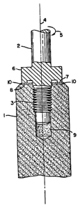
Referring to the drawing, a graphite shaft
with a female thread is represented by the numeral
l, and is connected to a metal shaft 2 having a male
thread by means of the threaded connection
D-15170-l
"
- 6 - 1312473
~herebetween represented overall by the numeral 3.
The shafts will be seen to have coincidental axes on
center line 4. In practice, metal shaft 2 is driven
in such a direction 5 as to tighten the joint
between the shafts against resistance to rotation of
graphite shaft 3. Metal shaft 2 is constructed with
a flange portion 6 that provides a lower seating
surface 7 that contacts a portion of the upper end
surface 8 of graphite shaft 1 upon fastening of the
shafts through threaded connection 3 in the opening
9 of said graphite ~haft 1.
The desired increase in torque strength of
the threaded connection is accomplished by applying
a thin layer 10 of refractory cement to the said
upper end surface 8 of graphite shaft 1 in the
portion thereof that comes into contact with lower
seating surface 7 of metal shaft 2 when the two
~hafts are screwed together to provide the desired
. threaded connection. Coa~ing 10 is allowed to dry
20 completely before the two 6haft parts are
. assembled. Thus, the cement is bonded to the
graphite surface, but not to the metal shaft flange
seating surface 7. The substantial increase in the
ability of the threaded connection of the invention
to transmit torque, as compared to such a threaded
` connection not prepared by incorporation of the
coating procedure of the invention, is caused by the
. greatly increased friction coefficient between the
refractory coating in the graphite surface and the
metal surface of 6aid flange portion ~ of the metal
flange as compared with ~he friction between the
untreated graphite 6urface and the metal shaft
~,
, D-15170-1
,
.
~ 7 ~ 1312473
flange in a conventional metal-graphite threaded
connection.
Those skilled in the art will appreciate
that any conveniently available refractory cement or
like coating material capable of providing an
increase in friction with the metal flange surface
as compared with that provided by untreated graphite
can be employed in the practice of the invention.
Illustrative of such coating materials is Zircar
Alumina Cement produced by Zircar Products Co. of
Florida, New York. This refractory cement i5
described as comprising 70% alumina in a combination
of milled fibers and sub-micron particles, together
with a small amount of an aluminum organic
derivative to enhance its bonding characteristics,
in a water-based binder composition. The cement can
be applied in its as-received condition. It has
been found somewhat easier to apply a smooth,
uniform coating, however, if the cement is ground to
break up some of the small agglomerates therein and
is then screened through about 100 mesh screening.
In either case, the cement is applied to the end of
the graphite shaft by pressing a brush of material
against the slowly rotating shaft, with a rotation
of in the ord0r of about 150 rpm having been found
convenient in particular applications. A flat
synthetic fiber artist brush is convenient and is
found to function well for this purpose. This
method of coating assures that the coating will be
of fairly uniform thickness around any circular path
and hence the application of the coating will not
destroy ~he necessary accuracy of the surface being
D-15170-1
. .
.,
- 8 - t 31 2473
coated. It should be noted that the entire upper
end surface of graphite shaft 1, i.e., upper end
surface 8, can be coated for convenience of
operation, as is shown in the drawing. For purposes
of the invention, however, it will be appreciated,
as indicated above, that it is only necessary ~o
coat the portion of said upper end surface 8 that
comes into contact with lower seating surface 7 of
said metal flange 6.
The coating of said upper end graphite
surface is usually, but not necessarily,
accomplished by applying the coating in two
operations that can be performed without any
appreciable time period ~herebetween. For example,
it is convenient to carry out such operations in
practical commercial embodiments about 1/6 to 1~2
minute apart. Some of the binder phase of the first
coating application is absorbed by the porosity of
the graphite being coated, and the second coating
application serves to replace such absorbed
material. The coating of the invention is allowed
to air dry before use, and no special drying or
baking operation is required.
The coating as applied in the practice of
the invention has typically been found to be about
1.2 to 1.4 mils thick when the cement used has been
ground and screened as indicated above, and about
1.4 to 1.9 mils thick when the cement is used in its
as-received condition from the supplier thereof.
Such thickness i~ measured over the original
graphite surface. It will be appreciated that some
penetration of the coating material into ~he pores
D-15170-1
, i
- 9 -
1 3 1 2473
of the graphite occurs 60 that the total thickness
of the coating will be greater than indicated above
in some parts of the treated surface.
Those skilled in the art will appreciate
that various changes and modifications can be made
in the details of the invention as her~in described
without departing from the scope of the invention as
set forth in the appended claims. For example, the
metal and graphite shafts used in the practice of
the invention are generally constructed as
illustrated in the drawing for practical operating
. purposes. It should be understood, however, that
the joint therebetween could also be made by
providing a graphite shaft having a male thread, and
graphite shaft having a shoulder for contact with
the metal shaft upon tightening of the joint, and a
metal shaft having a female thread. In this case,
the coating applied in the practice of the invention
would be applied to the flat contacting surface of
the shoulder of the graphite piece.
Illustrative examples of other refractory
cement compositions that can be employed in the
practice of the invention are coating materials
referred to herein as No. l Mixture and No. 2
Mixture. Both mixtures use sodium silicate as a
binder. The No. l Mixture has the following
composition:
Cab-0-Sil silica 0.5g
Sodium ~ilicate solution
(18% solids) lO.Og
Buehler levitated
alumina 6435AB 2.0g
8uehler 40-6625 AB 25u
alumina 1.Og
35 Ivory liquid l drop
D-15170-1
'
.
-- 10 --
1 31 2473
The Cab-O-Sil silica is employed to make
the coating mixture thick and easily painted on the
graphite surface. It also serves to keep the binder
liquid from being removed from the coating rapidly
by the capillary action of the porous graphite. The
alumina powders provide the high friction
characteristic desired, with the levitated alumina
also assisting in the spreadability of the mixture.
The Ivory Liquid assures wetting of all powder
particles and the wetting of the graphite by the
mixture. No special order of addition, and no
particular mixing techniques are required for the
preparation of the mixture. The coating as
conveniently applied and dried typically measures
about 0.6 mils thick over the original graphite
surface, as compared with the thicker coatings
obtained upon use of Zircar Alumina Cement. This
thickness does not include material that has
penetrated and filled the surface pores of the
graphite. As compared with said Zircar Alumina
Cement, said ~o. 1 Mixture has the disadvantage that
it tends to separate into a solid and a liquid phase
in a few hours and that it gels in a day or 60.
Thus, it should generally be freshly mixed within a
few hours of its intended use.
The No. 2 ~ixture has the following
composition:
Cab-O-Sil silica 0.5g
Sodium silicate solution
(18% solids) lO.Og
Buehler 40-6625 AB 25u
alumina 2.0g
Buehler B (Linde B Alumina) 0.5g
Buehler levitated alumina
40-6435AB 5.0g
Ivory liquid 1 drop
D-15170-1
i
- 11 - 1312473
This mixture can be mixed in the same manner as said
No. 1 Mixture and has similar properties when
applied to graphite.
Those skilled in the art will appreciate
that the material combinations referred to above are
illustrative of the types of cement that can be used
in the practice of the invention. In gsneral, the
refractory cement used for the practice of the
invention should comprise (1) a powdered material
with individual particles that do not melt,
disintegrate, or break up under the conditions of
operation; (2) a binder phase that will hold the
particles together and also bond them to the
graphite, 6aid binder retaining its strength at
operating conditions, (3) the combination of said
powdered material and binder phase being one
available in easily spreadable form, and (4) said
cement having, or being made to have, limited
absorption of the liquid binder phase into the
2Q graphite porosity. The thicXness of the coating
applied will be understood to vary somewhat
depending upon the characteristics of the particular
coating employed in any particular application with
thicknesses of from about 0.5 mil up to about 2 mils
2~ being generally satisfactory as will be seen from
the illustrative examples above.
The invention has been demonstrated in
various i1lustrative tests. It should be understood
that ~uch tests, and the results thereof, as
presented herein are for such illustrative purposes
only, and should not be construed as limiting the
scope of the invention as recited in the claims. In
:
~ D-15170-1
.,
:
. . .
- 12 - 1 ~1 2473
order to evaluate joint torque strength, an assembly
was made to provide a threaded connection as shown
in the drawing. Normally, the graphite shaft is
held stationary, while torque is applied to the
metal shaft with a torgue wrench. The torque
required to break the joint is noted. This test i8
generally made at room temperature in air for a
first evaluation. This is followed by tests at
350C or 450C in argon, or argon containing a small
amount of chlorine, to simulate actual use
conditions.
One of the factors to be considered in the
making of such tests lies in the fact that there i6
a factor of about 2 in torque strengths of joints
made with different starting graphite materials.
For example, the particular joint most frequently
used shows a room temperature torque strength
ranging from 25 to 50 foot pounds. The major
concern, of course, is with joints having torque
strengths in the low end of the scale. In order to
properly evaluate the effectiveness of the coating
~f the invention, two or more samples were made from
the same piece of graphite, wi h one sample being
tested in its untreated, as-is condition in air at
room temperature, and the other or others being
coated and tested at various conditions for
comparative purposes. The threaded connections that
` employed graphite shafts treated in accordance with
. the invention using the Zircar Alumina Cement
referred to above were found to be from about 65% to
about 115% stronger than the similar joints made
using uncoated graphite. The greatest increase in
D-15170-1
.
r,
- 13 - 1 3 1 24 73
torque strength was found to occur with respect to
the weaker starting materials. This desirable
increase in torque strength persisted when the joint
was tested a~ 350OC to 450OC in argon plus 3.6
chlorine, common temperature and atmosphere
operating conditions.
In a comparative test employing the No. 1
Mixture referred to above, a threaded connection in
which untreated graphite was employed failed at 39
foot pounds of torque at room temperature. A
comparative joint in which the contacting surface of
the graphite was coated with said mixture, measuring
0.5 mils, was tested at 350C in said argon plus
3.6% of chlorine atmosphere and was found to have a
substantially higher torque strength, said threaded
connection of the invention failing at 85 foot
pounds.
In a series of additional tests, a single
graphite piece was tested at room temperature and
was then cut into samples for high ~emperature
testing. Each set of samples tested consisted of
two pieces machined so that the threaded ends
thereof were taken from adjacent locations in the
original graphite piece. An original piece was
tested at room temperature, and ~he thread failed at
a torque of 40 foot pounds. Four pieces were cut
from thi6 original piece and were tested in two
comparative SQt& of uncoated and Zircar cement
coated pieces as ollows at 35QC in air: In Set
No. 1, the uncoated piece failed at a torque of 49
foot pounds, while the piece coated in accordance
with the in~ention reached a torque of 80 foot
D-15170-1
- 14 - 1312473
pounds without failure at the time the test was
stopped. Set No. 2 produced a similar result with
the uncoated piece failing at 40 foot pounds, while
the coated piece reached said 80 foot pounds without
failure at the time the test was stopped.
Another single graphite piece that failed
at 39 foot pounds in room temperature tests was cut
into four pieces and was tested in two additional
sets of comparative tests at 350OC in air. In the
Set No. 3 tests, the uncoated piece failed at a
torque of 40 foot pounds, and in Set No. 4, the
uncoated piece failed at 43 foot pounds. In the Set
No. 3 and the Set No. 4 tests, the coated piece did
not fail, and the tests were stopped a~ a torque of
8C foot pounds. The coated samples from Sets No.
1-4, which did not fail in said comparative tests,
were then machined to remove the coating and to
expose fresh graphite. Two of such newly prepared
samples were then coated with said Zircar cement,
and the four pieces, two coated and two uncoated,
were then tested at 350C in argon plus 3.6%
chlorine. In such tests, the uncoated samples from
Set Nos. 1 and 2 failed at a torque of S5 foot
pounds, while the corresponding coated samples
: 25 failed at 67 foot pounds. The uncoated samples from
Set Nos. 3 and 4 failed at a ~orque of 40 foot
pounds, while the coated samples reached a torque of
70 foot pounds prior to failure.
Further comparative tests were carried out
using a graphi~e piece that failed at 26 foot pounds
in room temperature tests. Four pieces were thus
cut therefrom and were tested at 350C in argon plus
. .
.,
;'
D-15170-1
,
.,.
- 15 - 1 3 1 2473
3.6% chlorine. One set resulted in torque failures
of 31 and 50 foot pounds, respectively, for the
uncoated and the Zircar cement coated samples. The
other set produced a similar result with the
uncoated and the ~ame coated samples failing at 28
and 61 foot pounds, respectively. In another such
test under the 6ame conditions and using the same
coating, a graphite piece that failed at 30 foot
pounds in air was cut into an uncoated sample that
failed at 25 foot pounds and a sample from an
adjacent location in the original piece that, as in
the other tests reported a~ove, had a substantially
higher torque strength, failing at twice the
strength, i.e. 50 foot pounds.
One graphi~e shaft that failed at 39 foot
pounds in room temperature testing was cut into
five pieces. Each piece was tested in argon plus
3.6% chlorine with ~he following results:
Piece Coating Test Temp. Torque to Failure
2 0 NQ__ Mat~ C (foot ~oundsl
: 1 Sodium silicate 35û 85
No. 1 Mixture
2 Sodium silitate 45û S0
No. 2 Mixture
2 5 3 None 450 33
4 Zircar Alumina Cement 450 90
(ground and screened) (did not fail)
Same as 4 450 80-90
Attention is specifically directed to the
alternative embodiment6 of the invention wherein a
. ~olid coating is bonded to the graphite surface,
D-15170-1
,
.,
.,
- 16 -
1 31 2473
said coating having been deposited by coating said
graphite surface with a solution or colloidal
dispersion of said material and then drying said
solution or colloidal dispersion, leaving said solid
material bonded to the graphite surface. In such
embodiments, the powdered material referred to above
and generally employed in preferred embodiments of
the invention need not be employed. That is,
solutions or colloidal dispersions, such as the
sodium silicate solutions used as a binder phase in
the illustrative examples described above, can be
employed without the incorporation of alumina
powders or other such powders used to produce the
types of cements described above with respect to
preferred embodiments of the invention.
The solid coatings employed in such latter
embodiments of the invention comprise solid material
that remains solid and is hard and adherent to the
surface of the graphite shaft under the operable
conditions of use of the thus-coated graphite shaft
in a threaded connection with a metal shaft, as in
aluminum refining operations. It will readily be
appreciated that the solid coating will not be
effective if it is of hard guality, but is only
weakly adherent to the surface of the graphite.
Likewise, if the solid coating were adequately
adherent to the graphite surface, but was of a soft
quality, it would not be effec~ive for purposes of
the invention. As with respect to the more
preferred embodiments referred to above, it should
be noted that the solid coating of such latter
embodiments is bonded to the graphite surface, not
D-15170-1
.
- 17 -
1 31 2473
to the metal shaft of the threaded connection. For
this reason, the solution or colloidal dispersion of
the solid material is coated and thoroughly dried so
as to leave the solid material bonded to the
graphite surface, prior to joining the treated
graphite shaft with a corresponding metal shaft to
complete a threaded connection therebetween.
While the sodium silicate solution used as
binder phase in the illustrative examples set forth
above can be effectively used to deposit a solid
coating bonded to the graphite surface, it should be
noted that, surprisingly, routine tests with various
commonly available solutions or colloidal
dispersions of said material have indicated that not
all of such solutions or colloidal dispersions serve
to deposit a solid material that is bonded to the
graphite to form a hard and adherent coating
suitable for use in the practice of the invention.
In most cases, the coatings that are sa~isfactory
can be determined simply by applying a coating
thereof to a graphite surface and determining that
the coating is adheren~ and not easily scraped off
from the graphite surface. By contrast in such
simple, routine experimentation, coatings from
unsatisfactory solutions or colloidal dispersions
will usually be found to be readily scraped from the
graphite surface, even under only fingernail
pressure.
; Solid solutions or colloidal dispersions
that can be effectively employed in the practice of
said latter embodiments of the invention include
sodium æilicate solutions, as indicated above,
.,
~ D-15170-1
,~,
s
.,
~ .
.,
r .
- 18 - 1 31 2473
colloidal alumina dispersions, and aluminum acetate
solutions. It will be appreciated that such
convenient materials are merely illustrative of the
broader range of solutions or colloidal dispersions
that can be determined by simple routine testing, to
be effective in forming on the graphite surface a
hard, adherent solid coating useful for purposes of
the invention. Potassium silicate and aluminum
formate solutions are examples of such other
materials. By contrast, a variety of materials ha~e
been found ineffective in pro~iding a hard, adherent
solid coating bonded to the graphite surface.
Included in this latter category are colloidal
silica, magnesium acetate, lithium 6ilicate and
sodium metaborate.
It will be appreciated that the solid
coating is very easily deposi~ed on the graphite
surface, as by painting a uniform coating of said
solution or colloidal dispersion of the desired
material on the graphite surface. The graphite
piece can conveniently be turned or rotated while
the solution or dispersion is brushed on the
graphite surface, after which said ~olution or
dispersion can be dried. As the first such
applications will tend to soak into the pores of the
graphite, the application of the solution or
colloidal dispersion i6 made repeatedly so as to
build up a thin, uniform layer of the coating on the
surface of the graphite, as in the other embodiments
described above. The concentration o the solution
or dispersion, the applicable temperature, the
porosity of the graphite ~urface, and the like will
.
D-15170-1
~'
- 19 1 3 1 2 4 7 3
be understood to affect the number of applications
that wDuld be made in any particular case to assure
a sufficient build-up of a coating thickness to
cover the surface of the graphite. In typical
applications, the coating procedure may be repeated
so as to apply from about 5 to 10 coating steps,
although either more or less such coating steps
might be employed in any particular case. It is
also within the scope of the invention to position
the graphi~e shaft in a vertical manner so that the
graphite surface to be treated is in a horizontal
plane, as in the Fig. 1 position, with ~he coating
being applied as in a puddle, 60 that the coating
can soak into the pores o the graphite and leave a
thin layer of coating on the surface in one
application.
In an example illustrating the latter
embodiment of the invention, a sodium silicate
solution containing 30% solids by weight in water
was prepared using Fisher Scientific sodium silicate
solution No. 50-5-338. This solution was applied to
the pertinent surface of a graphite shaft by
rotating the shaft and brushing the solution onto
the surface thereof. The solution was applied in
this manner four times, allowing about two minutes
! drying time between each application, thereby
forming a thin layer of solid ~oating covering all
of the graphite surface being treated. Upon drying
the last solution application, the solid coating was
baked at 800F (427C) to simulate conditions of
use. Upon testing the thus-treated graphite shaft
at room temperature, the friction torque readings
,
D-15170-1
,
.,
- 20 - 1~12473
obtained indicated that the torque strength of the
treated shaft was about 120% that of the
corresponding untreated graphite shaft.
For purposes of a similar test, a colloidal
alumina dispersion having 28% solids, i.e. alumina
rigidizer/hardener of Zircar Prod. Co., was
employed. The coating was applied by brush to a
rotating graphite shaft. The colloidal dispersion
was applied in this manner five times, with about
two minutes drying time between each application, to
build up the coating sufficient to fully cover the
treated surface of graphite. Upon drying the last
solution application, the solid coating was baked at
800F to simulate conditions of use. Upon testing
the thus-treated graphite shaft at room temperature,
the friction torque readings obtained indicated
about a 100% increase in torque strength of the
treated shaft as compared to that of the untreated
graphite ~haft.
In this illustrative example, a dilute
aluminum acetate water solution obtained by
separating the liquid binder from the solid phase of
the Zircar ~lumina Cement referred to above, was
employed~ ~he graphite shaft being treated was
- 25 coated 11 ~imes using this solution, with about two
minutes drying time between each application. Upon
~, thus obtaining a coating of the whole surface to be
treated, the coated surface was dried at 220C and
wa~ tested at room temperature. The torgue strength
increase over that of an untreated graphite shaft
appeared to be about 90%.
D-15170-1
:
- 21 - 1312473
From the various comparative tests
summarized above, it will be seen that the coating
of the portion of the upper surface of the graphite
shaft contacting the lower seating surface of the
metal shaft flange enables an improved threaded
connection to be achieved between a graphite shaft
and a metal shaft. Such coating of the graphite
contacting surface in accordance with the invention
thus appreciably ~trengthens the threaded connection
therebetween so that the ability of the connection
to transmit torgue is sub~tantially increased. The
.. invention, by enabling the torgue capacity of the
metal-graphite joint to be improved without
necessitating any radical change in design or any
increase in the size of the shafts, provides a
highly desirable advance in the aluminum refining
art. Graphite shafts coated as disclosed and
claimed herein thus enable ~he threaded connection
between metal and graphite shafts to withstand
substantially higher drivi~g torgues and shock loads
without the undue breaking of the graphite-metal
joint, or the cracking of the graphite shaft as
occurs more freguently in conventional aluminum or
aluminum alloy refining operations carried out
without benefit of the invention.
D-15170-l
.,