Note: Descriptions are shown in the official language in which they were submitted.
r~ / ~ 1 3 1 2 5 7 5
G: FLY
M~T~OD AND APPARATUS FOR EXTENDING
FL~ SECTION OF CRANE BO~M
Background of the ~nvention
This invention relates to multisection telescopic booms
such as used on mobile cranes or the like, and in particular to
means znd a method for extending and retracting the outermost
fly section of the crane which does not have its own power
source without the need for a second human operator and without
the need for the first operator to leave the cab or lower the
boom.
Various types of multisection, telescopic crane booms are
known and which need to be extended to great lengths, to handle
very heavy loads, and to be reLatively light and compact to
facilitate their mobility. Accordingly, it is customary to
design such cranes so that, in operation, the fly section is
extended and retracted by means other than power means located
in the fly section, in order to reduce the weight and expense of
the fly section. For example, Johnston, U.S. Patent No.
3,795,321, discloses a crane boom of the general type under con-
sideration, means and a method for extending a fly section
without its own power extension means, and describes a method oE
extending or retracting a fly section by connecting the movable
portion of a hydraulic ram to the fly section. To make this
connection, the crane operator must align several access and
pinning holes in the various boom sections, and because these
holes can only be visually aligned and the crane operator cannot
see the holes when controlling the boom sections from the cab,
~ ` ~ 1 3 1 2575
it is required that a second wor~er be positioned alongside the
boom sections to signal the crane operator when the holes are in
alignment.
The device of Johnston also re~uires heavy pins to connect
the fly section -to the second section when the former is retracted
or extended relative to the latter, which pins must be inserted
manually. This can be difficult even for a strong individual,
as the a~cess and pinning holes on larger cranes are often
several yards above the ground even when the boom is in its
lowermost position. This may necessitate the operator's climbing
in a ladder or otherwise being elevated to a level such tha-t the
pin can be inserted. Furthermore, the size o~ the pin con-
necting the Ely and second section or load pin is limited to the
size that an operator can lift in place. In the boom described
by the Johnston patent, where the load pin is inserted through
the sides of the fly section and the second section and is in
contact with both sections whether the fly section is extended
or retracted from the second section, the load pin must transfer
axial and bending loads. When the boom section is extended or
retracted, the load pin must transfer all axial loads from the
boom point to the rest of the boom. When the boom section is
extended, the load pin must also transfer all bending loads from
the boom point to the rest of the boom. Thus, in the extended-
or retracted position, the lift capacity of the boom is limited
by the shear strength of the pin, which in turn is limited by
the size pin the operator can lift in place.
The stop pins, which are used in the Johnston patent to
maintain the fly section's axial position relative to the base
section while other movable sections are being extended or
--2--
f 3 t 2 5 75
retracted, must also be inserted manually in Johnston, and are
thereby limited in size because of the factors listed herein-
above which limit the size of the load pins. In ord~r to fully
e~tend the fly section of Johnston's patented device, the stop
pins must be inserted therein. When the ~ly sec-tion in Johnston
has-been fully extended, the load pin must be inserted to main-
tain the fly in this extended position while the telescopable
sections are moved axially. If the stop pins are inadvertently
not removed from the fly section after the load pin has connected
the extended fly section and the second section, and the second
section is then telescoped into the third and base section,
breakage of the stop pin may result. Such breakage is more
lLkely when the stop pins are of relatively light construction,
and when access to and removal of the stop pins is relatively
difficult.
~ nother exa~ple of an apparatus for extending a non-self-
powered fly section is sho~n in Mentzer, U.S. Patent No.
4,490,951~ which discloses a latch mechanism $or remotely
operating and locking a manual fly section of a multisection
crane boom. However, the latch pin cylinder, hydraulic valve,
hoses and electrical wires are located inside the boom where
cost o service and access may be higher. ~oreover, the fly
section disclosed in that patent must be manually locked for
road travel, and manually unlocked before remotely extending the
boom. This manual operation defeats the purpose of having a
remotely operable fly section. In addition, only one latch pin
or stop pin is provided so that if this pin is inadvertently not
removed from the fly section after the load pin has connected
the extended fly section and the second section, and -the second
~;~ ~ 1312575
section is then retracted, uneven stresses, bending of the power
cylinder and even damage to the crane may result.
This invention relates to improvements over the inv~ntions
described above and to solutions to the problems raised thereby.
Summary of the Invention
A multisection telescopic boom of a mobile crane is pro-
vided with means for extendin~ a telescopic section thereo~
without power to that section and without the necessity of
anyone besides the operator in the cab to insert and remo~e the
pin means associated with the boom for locking the fly section
in certain positions. The pin means includes a load pin which
passes through the outermost powered section and engage.~ the fly
section to hold it in the re~racted posikion, such as for road
travel. An actuator mechanism is supplied to be operated re~
motely by the machine operator, for retracting the load pin and
keeping it retracted. When the outermost powered section is
fully extended together with the fly section, latch pins are
remotely actuated to engage the fly section and lock it to the
next lower boom section. The outermost powered section is then
retracted, in effect extending the fly section relative to it.
On completion of this retraction, the load pin again automati-
cally engages the fly section to lock it in its extended posi
tion with respect to the outermost powered section, and the
latch pins are remotely disengaged. A control circuit is pro-
vided so as to prevent the load pin and the latch pins from
being in their disengaged positions simultaneously, unless the
fly section is retracted in the outer section.
The invention provides a boom having a fly section which
1312575
7~2~17-1
does not have its own power extensionJretraction unit, but which
can nevertheless be fully extended and retracted, including
locking into place in either position, without any other aid to
the c~b operator.
Another aspect of the invention is to provide a boom as
described above wherein the fly section can be extended and
retracted, including locking into place in either position, with
the boom raised to any angle and even set up through a narrow
opening a~ a job site.
A more specific feature of the invention is to provide a
boom wherein the non-self-powerad fly section has a load pin which
enyayes the fly sectlon to the next section due to spring loading
automatically in both the extended and retracted pOSitiOIIS and
which is disengaged by a hydraulic cylinder or other power source
under direct control of the crane operator in the cab.
Another feature of the invention is to provide a boom
wherein the non-self-powe.red fly section is latched to a powered
section of the boom for extension, and then unlatched, by
hydraulic cylinders or other power means all under direct control
of the crane operator in the cab.
Yet another feature of the invention is to provide a
boom wherein the load pin and the latch pins are prevented from
being simultaneously disenyaged unless the fly section is
retracted within the outer powered se~tion.
Specifically, the invention provides in a crane a
telescopic crane boom including a first section, an outer section
lD~`
13125/5
74~47-1
and a fly section;
means to effect extension and retraction of said outer
section relative to said first section; and
apparatus for extending and retracting said fly section in
response to operation of said apparatus comprising:
load pin means for releasably connecting said fly section to
said outer section i.n at least two positions, including a
retracted position and an extended position;
means for locking said load pin means in either of two
positions, including an attached position wherein relative
movement between said fly section and said outer section is
prevented and released position wherein such relat:lve movement is
allowed;
release means for moving said load pin means to said released
posltion, the~eby allowing relative movement between said fly
section and said outer section;
latch pin means to releasably latch said fly section to said
first section by a plurality of latch pin power means connected to
said first section;
resetting means for resetting said load pin means from said
: released position to said attached position; and
a release power means remotely controlled and attached to
said first section;
said load pin means including a lever pivotably connected to
said outer sec~ion, and a load pin connected to said lever~ which
load pin passes through a collar connected to said outer section
~ 6
1 31 2575
74~47-1
and into engagement with a hole in said fly section when in said
a-ttached position~ and which load pin means is caused to move from
said attached position to said released position by said release
power means.
Other aspects and advantages oE the invention will
hecome apparent hereinafter.
Description of the Drawin~s
Fig. 1 is a side elevational view of a mobile crane
having a boom with a fly section which is not self-powered, but
which .is extended by the operator from the cab, constructed
accorcling ko the invention.
Fig. lA, lB ancl lC are schematlc views o~ a crane boom
constructed according to the invention in various stages of
extension.
Fig. 2 is an enlarged view of a portion of the crane
boom shown in Fig. 1 partially cut away to show the latch pin
assembly.
6a
.~
1 31 2575
Fig. 3 is a further enlarged view of a smaller portion of
the crane boom shown in Fig. 2 showing the load pin release
mechanism and support therefor.
Fig. 4 is a cross sectional view, showing the load pin
release mechanism, taken along line 4-4 of Fig. 2.
Fig. 5 is a view of the apparatus shown in Fig. ~ showing
the load pin in the release position.
Fig. 6 is a view of the apparatus showing the load pin
beariny on the bottom of the fly section of the crane boom.
Fig. 7 is a fragmentary side view, partially in sectionl of
the load pin constructed according to the invention.
Figs. 8A and 8B are fragmentary cross sectional views of
the load pin mechanism showing the spring loaded plunger in two
of its diEferent positions, taken along line 8-~ of Fig. 7.
Figs. 9 and 10 are bottoln views of the apparatus shown in
Fig. 3 and show the reset cam acting on the spring loaded
plunger to reset the load pin.
Fig. 11 is a sectional view of the latch pin assembly
showing the latch pins in the disengaged position, taken along
line 11-11 of Fig. 2.
Fig. 12 is a view similar to Fig. 11, showing the latch
pins in the engaged position.
Fig. 13 is a cross sectional view of Fig. 12, taken along
line 13-13, showing an end view of the latch pin carriage.
Fig. 14 is a cross sectional view of Fig. 12, taken along
line 14~14, showing a side view of a latch pin.
Fig. 15 is a schematic diagram of the electrical circuit
provided to ensure that the load pin and latch pins are
generally not all disengaged at the same time.
1 3 1 2 5 75
Fig. 16 is a schematic diagram of a portion of the
hydraulic circuit which works with the electrical circuit shown
in Fig. 15 to ensure that the load pin and the latch pins are
generally not all disengaged at the same time.
Descri tion of the Preferred Embodiments
Referring now to Fiy. 1, there is shown a self-propelled
crane generally at 10, carrying a telescopic crane boom 12.
Crane 10 also includes a lower section 14 on which an upper sec-
tion 16 is mounted by means of a slew ring assembly 18 ~or rota-
,
tion in either direction to an unlimited degree about a verticalaxis during crane operation. Lower section 14 comprises a
chassis 20 on which are mounted a plurality of wheel assemblies
such as 22, a Eixed ring 24 oE the aEoresaid slew ring assembly
18, four extendible outriggers such as 26 for deployment during
crane operation, a source of power such as an internal com-
bustion engine 27 for providing operating power to the crane and
for providing motive power for the wheel assemblies 22, and a
hydraulic fluid reservoir 28 for supplying operating fluid to
certain vehicle and crane components. Upper section 16 com-
prises a rotatable ring 30 of the aforesaid slew ring assembly
18 and a support frame 32 which is rigidly secured to ring 30.
A boom support assembly 34 is rigidly moun-ted on support frame
32 and telescopic boom 12 is mounted by means of a pivot
assembly 36, including a pivot pin 38, on support frame 32 for
pivotal movement such as by boom hoist cylinder 39, between
raised and lowered positions about a horizontal axis during
crane operation. In the description which follows, the word
"inner" when referring to a particular end of a boom section or
-8-
1 3 1 2 5 7 5
a particular section itself, is used to mean closer to boom
support assembly 34, while "outer" is used to mean further
from ~oom support assembly 34O Telescopic boom 12 includes a
base boom section 40, an inner boom section 42 telescopable
within the base boom section, an outer boom section 44 tele-
scopable within the inner boom section, and a manual ~ly section
56, that is, a fly section without its own power means for
extension or retraction, telescopable within outer boom section
44. Supporting frame 32 also affords support for two cable
winches such as 46, a counterweight 48 and an operator's cab 50.
Boom 12 terminates in a boom head 52~ Also located on chassis
20 is a carrier cab 54.
The operation of extending the fly section 56 of the boom
12 can be seen schematically by comparing Figs. lA, lB and lC.
The preferred details of the various components reEerred to will
be set forth after the schematic explanation. In Fig. lA, the
boom 12 is shown in the completely retracted position. Power
means ~or extending and retracting inner boom section 42 and
outer boom section 44 are shown in Fig. lA to be hydraulic
cylinders 43 and 45 respectively. These cylinders 43 and 45 are
elongated in shape and have extendable and retractable outer
portions 43a and 45a connected at their inner ends by any
suitable means such as pins 47 and 49 to inner boom section 42
and outer boom section 44, respectively. Similarly anchor por-
tions 43b and 45b of these cylinders may be connected by pins 51
and 53 to base boom section 40 and inner boom section 42,
respectively.
When the boom 12 is in the travel position as shown in Figs.
1 and lA, a load pin 58 (Fig. lA) slidably mounted via a collar
~ 1312575
60 to the outer end of outer section 44 and engages a hole
56a at the outer end of fly section 56 to prevent relative move-
ment between outer section 44 and fly section 56. Load pin 58
i5 held in engagement by an engagement-disengagement apparatus
61 which includes a lever 62 pivotably attached to the outer end
of outer section 44 and biased upward by biasing means 66. The
first step in the fly section extension operation is to dis-
engage the load pin 58 from fly section 56. This is accom-
plished by a hydraulic cylinder 70 or other power source con-
nected at the outer end of base section 40, extending and
pivoting lever 62 downward to the position shown in phantom in
Fig. lA. This in turn disengages load pin 58 from load pin hole
56a in Ply section 56. Cylinder 70 i9 in position to disengaye
load pin 58 only when the cylinder is aligned over the distal
end of lever 62. Notice that this occurs only when outer sec-
tion 44 is fully retracted with respect to base section 40~
When cylinder 70 is extended, the load pin is disengaged and
held so by a plunger 78 which is biased outward within load pin
58. Next, outer boom section 44 is fully extended by use of its
power cylinder 45 as shown in Fig. lB, carrying with it the fly
section 56 with load pin 58 locked in disengaged position by
plunger 78. The ne~t step in the process is that a latching
means 86, attached to the outer end of inner section power
cylinder 43, is caused to engage fly section 56 at a hole 56c as
shown in phantom in Fig. lB. This latching can be accomplished
by any suitable means such as a pivoting toggle assembly 110
actua-ted by a power source such as a hydraulic cylinder 126
attached to the outside of base section 40 accessing toggle
assembly 110 through access holes 44a, 42a and 56d in the
--10--
`j 1 3 1 2 5 7 5
respective section. Hence, fly section 56 is affixed to inner
boom section power cylinder 43 which is already fully retracted.
Because the inner end of cylinder 43 is connected to base sec-
tion 40, and because the latching is only accomplished when
cylinder 43 is fully retracted, it would be equivalent for
latching means 86 to affix fly section 56 to base section 40.
For this reason when the term "first seCtioD" is used herein~
after, it will be taken as referring to the base section 40 and
the inner section 42. The next step is to retract outer boom
sec~ion 44 to the position shown in Fig. lC. Since fly section
56 is now attached to inner boom section power cylinder 43, it
remains extended with the retraction of the outer boom section
44. This, in turn, causes relative movement between fly section
56 and outer boom section 44. On the occurrence of this rela-
tive movement load pin resetting means 84 pushes in plunger 78
and resets load pin 58, allowing it to move upward so that it
rides against the bottom of fly section 56, as shown in phantom
in Fig. lC, until full retraction of outer boom section 44 is
achieved~ at which time load pin 58 snaps into engagement with
the inner locking hole 56b in the bottom of fly section 56.
Flnally, the latching means 86 is disengaged from fly section 56
by cylinder 130, which is mounted on the outside of base section
40 and contacts the latching means 86 through access holes 42b
and 44b in the respective boom sections. At this point the fly
section 56 is loc~ed in extended position and the two self-
powered sections 42 and 44 may be freely extended or retracted
as needed.
The fly section 56 may be retracted by reversing the proce-
dure. In particular, inner section 42 and outer section 44 ara
--11--
~--" 1 3 1 2575
fully retracted. Cylinder 126 actuates toggle assembly 110 Yia
access holes 42a and 44c to engage latching means 86 to fly sec-
tion 56. At the same time, cylinder 70 dis~ngages load pin 58
~rom inner load pin hole 56b. Plunger 78 locks load pin 58 in
the disengaged position. Outer section 44 is then extended, in
effect telescoping fly section 56 into it~ Just before it
reaches full extension, Lesetting means 84 resets load pin 58,
which snaps upward against the bottom of fly section 56. Then,
when full extension of outer section 44 is reached, load pin 58
engages outer load pin hole 56a. Cylinder 130 then disengages
latching means 86 from fly section 56 through access holes 44d
and 42b of the respective boom sections. Then when outer sec-
tion 44 is retracted, fly section 56 is locked to it by loacl pin
58.
As can be seer., all of the above steps may be accomplished
by the operator from the cab by control of hydraulic cylinders
7U, 126 and 130 connected to the base section 4U, even with the
boom 12 positioned through a naxrow opening and at any overhead
position. Since the cylinders are connected to the base sec- ~
tion, no hose loops or hose reels are reguired. Moreover,
access holes allow visual inspection of latch pins for improved
safety and, if necessary, manual operation of the latch pins.
And the size of the various pins required can be determined
based solely upon the masses and stresses expected to be encoun-
tered in operation of the crane boom, without regard to whether
or not an operator is physically able to manipulate and handle a
pin of the particular size required.
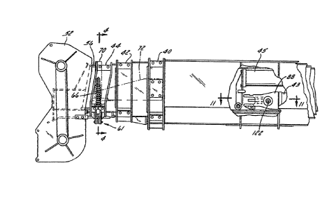
Figs. 2 through 5 show the preferred arrangement of the
load pin 58 and the apparatus 61 for releasing and engaging the
.
-12-
1 31 2~75
load pin. The purpose of the load pin 58, shown best in Fig. 4,
iq to preven~ ~ly section 56 from moving with respect to outer
boom section 44. As shown in Fig. 4, the load pin 58 passes
through a collar 60 affixed to the outer boom section 44 and
engages a hole 56a in the bottom of fly section 56. The load
pin 58 is held in hole 56a by a spring biased lever 62 having
one end pivotably attached to the frame 64 of outer boom section
44 and the other end connected via a spring strut 66 to a tab 68
which is, in turn, connected to the side of outer boom section
~4. Spring strut 66 is a telescoping strut resiliently loaded
and biased to the contracted position. As shown best in Figs. 2
and 3, lever 62 is preferably a double link which straddles the
flattened lower end 58a of load pin 58. Lever 62 engages load
pin 58 by means oE slots 62a into which are fitted a pin 58b
projecting from both of the flats of end 58a. (Slots 62a are
necessary to be slots because of the pivoting action of lever 62
combined with the sliding action of load pin 58 within its
collar 60.) In order to disengage load pin 58 from fly section
56, a means to actuate assembly 61 is required. In the embodi-
ment shown, a hydraulic cylinder 70 is connected to boom base
section 40 by a bracket 72 (Fig. 3). Bracket 72 locates
cylinder 70 so as to be over the same end of lever 62 as is con-
nected to strut 66 when outer section 44 is in its fully
retracted position. Hydraulic cylinder 70 preferably is a
double acting cylinder and a small hydraulic pressure is main-
tained on the rod side when not in use to hold the cylinder in
the retracted position. This can also`be a single acting
cylinder with a spring return (not shown). A piston 73 of
cylinder 70 terminates in a push pad 74, which is aligned to
-13-
1 2 5 7 5
contact a roller 76 at the end of lever 62. Thus when the
cylinder 70 is activated push pad 74 forces roller 76 and, in
turn, lever 62 downward. This action draws load pin 58 downward
and out of hole 56a, such tha~ fly section 56 is free to slide
or otherwise move with respect to outer boorn section 44. This
unlocked position is shown in Fig. 5. Were it not for plunger
78 described in more detail below, load pin 58 would then slide
right back into the hole 55a in the bottom of fly section 56,
since it is biased upward by strut 66. Instead, plunger 78
locks load pin 58 out of hole 56a until the fly section 56 is ~
slid far enough out of outer section 44 so that the pin 58 and
hole 56a are no longer aligned. Pin 58 is then allowed to move
upward and bear on the bottom of fly section 56, as shown in
Fig. 6, until inner load pin hole 56b is encountered, at which
point the pin will snap upward into the hole and assume the
position shown in Fig. 4, with the fly section in the extended
position.
The plunger 78 referred to above is shown in more detail in
Figs. 7, 8A, 8B, 9 and 10. As shown in Figs. 7, 8A and 8B~ a
plunger 78 is spring loaded transversely within load pin 58,
biased outward by an internal spring 80, and protrudes partially
out of the side of pin 58. Plunger 78 preferably has two
distinct diameters. The tip 78a of plunger 78 is of relatively
smaller diameter while the base 78b is of larger diameter.
Referring to Fig. 7, collar 60 has a slot 60a having a narrower
portion 60b and a wider portion 60c. When load pin 58 is in the
engaged position as shown in Fig. 4, plunger 78 is in the
narrower portion 60b of slot 60a ~Fig. 7), and only the tip 78a
protrudes outside the load pin 58 itself (Fig. 8A). When the
-14-
1 2575
load pin 5~ is in the lowered position as shown in Fig. 5,
plunger 78 has been moved to align with the wider portion 60c of
slot 60a, and base 78b of plunger 78 is allowed to reach outside
collar 60, as shown in Fig. 8B. Plunger 78 is retained within
load pin 58 by any suitable means such as a retainer plate 82
bolted or otherwise removably affixed over slot 60a and having
its own slot 82a which runs parallel to slot 60a but has only a
single width matching that of narrower portion 60b of slot 60a.
Thus retainer plate 82 allows the required vertical motion of
plunger 78 and prevents loss of the plunger. In this manner the
load pin 58 i9 allowed to move downward b~ the action of lever
6~ ~Figs. 4 and 5). Once it has done'so, plunyer 78 snaps into
the large part 60c o~ slot 60a, and prevents the load pin 58
from moving back up again due to the pressure of strut 66. 'The
only way to release load pin 58 and allow it to move back up is
to push the plunger 78 back into the load pin 58 so the body 78b
is not in the larger portion 60c of slot 60a.
Figs. 9 and 10 show a reset means 84 provided for the pur-
pose of pushing in the plunger 78 when needed. This reset means
84 is in effect a cam secured to the underside of fly section 56
by any suitable means and may be adjustable so as to actuate the
plunger to the proper extent at the proper time. Thus when load
pin 58 i5 in place in hole 56a as shown in Fig. 4, or when it is
~irst dropped out of the hole SGa as shown in Fig. 5, plunger 78
is aligned with a low area 84a of the cam of reset means 84, as
shown in Fig. 9, and the plunger is allowed to pop out as
described above with reference to Figs. 7 and 8B. Plunger 78
has thus locked load pin 58 in the disengaged position as shown
in Fig. 5. When outer boom section 44 then moves with respect
-15-
~ ~:) 1 3 1 2575-
to fly section 56, plunger 78 must pass over a high area 84b of
the cam of reset means 84, as shown in phantom in Fig. 10.
This, of course, pushes plunger 78 in and allows load pin 58
back up, but by this time load pin 58 is no longer aligned with
hole 56a in the fly section 56, and so the pin 58 rides on the
bottom of ~ly section 56 (Fig. 6) until it encounters inner load
pin hole 56b, which then engages load pin 58. Outer load pin
hole 56a is located near boom head 52, and allowing load pin 58
to snap into that hole locks fly section 56 into its retracted
or travel position. Inner load pin hole 56b is loca-ted at the
inner end of fly section 56 and cooperates with load pin 58 to
lock the fly section in the extended position.
As described earlier, after the outer section 44 and ~ly
section 56 are fully extended together, the fly section is pre-
ferably latched by latch pin means 86 to the inner boom
cylinder 43 or base section 40 temporarily so that the outer
boom section 44 can be retracted from fly section 56. The latch
pin means 86 and toggle mechanism 110 are shown in Figs. 11, 12,
13 and 14. Fig. 11 shows the latch pin means 86 in its normal,
disengaged position. The latch pin means 86 includes a U-shaped
frame 88 which is securely but removably connected to the outer
end of hydraulic cylinder 43 by suitable means such as bolts 90.
As can be seen in the sectional view in Fig. 13, the latch pin
means 86 also includes an upper horizontal plate 92 and a lower
horizontal plate 94 affixed within the curve of the U-shape oE
frame 88. Two tabs 96 and 98 are connected to the underside of
lower plate 94 and horizontally spaced apart. These tabs hold
an axle 100 on which are journaled two wheels 102 and 104 for
facilitating the back and forth movement of the latch pin means
-16-
1 31 2575
86 with respect to fly section 56 on which it rests. Referring
again to Figs. 11 and 12, a pair of pivot pins 106 and 108 are
vertically connected between plate5 92 and 94 and horizontally
spaced apart. Journaled to these pins is the toggle assembly
110 which includes two toggle plates 112 and 114. Toggle plate
112 pivots on pin 106 while toggle pla-te 114 pivots on pin 108.
The two toggle plates are joined together by link portions 112a
and 114a integrally formed near the lengthwise center of the
respective plates and which join in a pin and slot arrangement.
As shown best in Fig~ 13, link 114a is preferably a double link
while link 112a is a single link. Further, link 114a holds a
pin 116 which engages a slot 112b in link 112a (Fig. 11).
Thus whenever plate 112 is caused to rotate on pin 106 in one
directioll, for exampl~ clockwise, plate 114 is thereby caused to
rota-te on pin 108 in the opposite direction, in the example
given counterclockwise. Referriny again to Fig. 11, each of the
plates 112 and 114 terminates at one end in a slot 112c and 114b
which mates with a pin 118 and 120. These pins are held in the
clevis portions 122a and 124a of a pair of latch pins 122 and
124 which, in turn, are laterally slidably mounted in pin guide
tubes 89 welded or otherwise attached to the sides of frame 88.
At least two of these latch pins are provided, arranged sym-
metrically about the longitudinal center line of the boom so as
to provide symmetry of support in case the boom were inadvert-
ently attempted to be moved with both the latch pins and load
pin engaged, so as to prevent damage to the boom. ~ sectional
view showing a side view of latch pin 122 and associated parts
lS given at Fig. 14. When fly section 56 is fully extended with
respect to base section 40 and inner section 42 is fully
! ~ ~ 1 31 2575
retracted, latch pins 122 and 124 align with a pair of openings
56c and 56e, respectively, in the sides of fly section 56. As
referred to above, Fig. 11 shows latch pins 122 and 124 in the
disengaged position. As shown in Fig. 12, these latch pins are
toggled into engaged position, that is, a position where they
are in fly seetion openings 56c and 56e as well as pin guide
tubes 89 at a time when the openings are aligned, by a hydraulic
cylinder 126 attached to the outside of base boo~ section 40.
As there shown, the piston 128 of cylinder 126 is aligned with
access holes 40a, 42a, 44a and 56d in the respective boom sec-
tions when the sections are retracted. When piston 128 is
extended as there shown in phantom, it contacts cam end 112d of
toggle plate 112. Piston 128 then exerts a push force on cam
end 112d o~ toggle plate 112, causing it to rotate clockwise
about pin 106, thereby causing toggle plate 114 to rotate coun-
terclockwise about its pin 108, in turn forcing latch pins 122
and 124 out oE assembly 86 and into holes 56c and 56e in fly
section 56. Another hydraulic cylinder 130 is provided to dis-
engage the latch pins 122 and 1240 As shown in Fig. 11, cylinder
130 is also attached to the outside of base boom section 4Q and
aligned with latch pin 122 and access holes 40b, 42b, 44b and
56c in the respective boom sections when the sections are
retracted. Then, when the piston 132 of cylinder 130 extended
as shown in phantom in Fig. 11 r the piston contacts the near
side latch pin 122 directly and pushes it out of opening 56e in
fly section 56 which, via toggle plates 112 and 114, also draws
opposite side latch pin 124 out o the opening 56d on that side
of fly section 56. Cylinders 126 and 130 are preferably double
acting eylinders. A small pressure is maintained on the rod
-18-
1 3 1 2 5 7 5
side when not in use to hold the cylinders in the retracted
position. This feature prevents the piston from sliding out
under vibratory conditions and avoids damage to the boom sec-
tions and the piston during the boom extension and retraction
operations. These cylinders may also be single acting with a
spring return (not shown). A spring biased detent means is pro-
vided to facilitate positive engagement and disengagement of
latch pins 122 and 124 to fly section 56. This detent means
includes a pair of transverse grooves provided in each latch
pin. Thus latch pin 122 has an engagement groove 122b near its
clevis portion 122a and a disengagement groove 122c nearer the
opposite end. Similarly, latch pin 124 has an engagement groove
1~4b near its clevis portion 124a and a disengagement groove
124c nearer the opposite end. Each latch pin is provided wikh a
locking ball 134 and 136, respectively, biased in the sides of
pin guide tubes 89 against each latch pin 122 and 124, and
located so as to snap into one or the other of the grooves, and
thereby provide positive positions for engagement and disengage-
ment of the latch pins 122 and 124.
As shown in Fig. 15, the crane 10 includes an electrical
circuit 138 for controlling the various power means and
hydraulic cylinders hereinbefore described. In particular, this
circuit 138 also includes means to prevent the load pin 58 from
being disengaged during the time the latch pins 122 and 124 are
disengayed, and vice versa, and means for disabling the power
cylinder 43 for inner section 42 when the load pin hydraulic
cylinder 70 or the latch pin hydraulic cylinders 126 and 130 are
in use. The circuit 138 includes a master switch SWl, closure
of which disables the cylinder 43 by means of solenoid 142.
-19-
``- ~ 1 3 1 2575
This is done to ensure that cylinder 43 is not energized during
the fly extension operation, since to do so could result in
damage to the pins or the cylinders. Means are provided to
indicate whether the load pin 56 and latch pins 122 and 124 are
engaged, and to show whether the fly section 56 is retracted
within the outer section 44. Further, means are provided for
preventing cylinder 70 from moving load pin 58 to it~ released
position if the latch pins 122 and 124 are disengaged and the
fly section 56 is not retracted, and for preventing cylinder 130
from moving latch pins 122 and 124 to their released positions
if load pin 58 is disengaged and fly section 56 is not
retracted. In the preEerred embodiment, a pair of switches SW2
and SW3 are provided to show the status of the latch pins 122
and 124. When the latch pins are disengaged as shown in Fig.
11/ switch SW2 is closed and an indicator lamp Ll, connected in
series therewith, is lit. When the latch pins move to their
engaged positions, as shown in Fig~ 12, switch SW2 is opened and
switch SW3 is closed, in turn lighting lamp L2 and energizing a
relay Rl. ~hus when the latch pins are disengaged lamp L1 is
lit while, when they are engaged, lamp L2 is lit. Switches SW2
and S~3 may be proximity switches or any other suitable switches
activated by the position of latching pins 122 and 124. Another
switch SW4 is located on boom 12 so as to be closed when load
pin 58 is in its engaged position. An indicator lamp L3, in
series therewith, is lit when switch SW4 is closed and acts as
an indicator showing that the load pin is engaged. In addition,
when switch SW4 is closed, a relay R2 is energiæed. A safety
override switch SW5 is provided, positioned on boom 12 so as to
be closed whenever the fly section 56 is retracted as shown
-20-
2 ~ q 5
schematically in Fig. lA, or whenever outer section 44 and fly
section 56 are extended. ~his switch SW5 controls two relays R3
and R4, so that both are energized when switch SW5 is closed.
As can be seen in Fig. 15, ~he contacts of relays Rl and R4 are
connected in parallel, as are the contacts of relays R2 and R3.
Hence, closure of switch SW5 has the effect of overriding relays
Rl and R2, and allowing an operator to disengage the load pin 58
and the latch pins 122 and 124 all at the same time. This is
not undesirable since it is only allowed when the fly section 56
is retracted within the second section 44, so that no hazard is
presented thereby. Assuming switch SW5 is open, however, the
operation of the circuit 138 is as follows, reEerring to both
Figs. 15 and 16. When latch pins 122 and 124 are engaged,
switch SW3 i~ closed and relay Rl is energized. Thi~ allows
load pin switch SW6, when pressed by the operator, to energize a
valve 146 of automatic pinning valve assembly 147 and, in turn,
disengage the load pin 58 via cylinder 70. Release of switch
SW6 closes valve 146 and opens valve 148 of assembly 147,
supplying the small but constant amount of retracting pressure
on cylinders 70, 126 and 130 as referred to earlier (Fig. 16).
Then, when load pin 58 is engaged, switch SW4 closes and ener-
gizes relay R2. This allows latch pin switch SW7, when pressed
on the léft side by the operator, to energize valve 150 of
assembly 147 and, in turn, engage latch pins 122 and 124 via
cylinder 126. Or the operator can press the right side of
switch SW7, which energizes valve 152 of assembly 147 to
disengage latch pins 122 and 124. As with switch SW6, release
of switch SW7 energizes valve 148 (shown best in Fig. 16) to
provide the small amount of back pressure required to retract
-21-
1312575
the pistons of cylinder 70, 126 and 130.
Hence circuit 138 provides a means for controlling the
various power cylinders or power means and ensuring that the
load pin and both latch pins are prevented irom being disengaged
at the same timer since to allow them all to be disengaged could
result in uncontrolled movement of the fly section 56 with
respect to the outer section 44.
While the apparatus hereinbefore described is effectively
adapted to fulfill its intended objectives, it is to be under-
stood that the invention is not to be limited to the particular
preferred embodiments of method and apparatus for extending the
fly section of a crane boom herein set forth. Rather, the
invention is to be taken as including various reasonable e~uiva-
lents without departing f.rom the scope oE the appended claims.
-22-