Note: Descriptions are shown in the official language in which they were submitted.
2 13~79
BACKGROUND of the INVENTION
The present invention relates to a jig designed
for welding the mitered corners of window and door
frames fashioned from molded plastic section.
Conventionally, the sash and surround frames of
05 plastic window and door fixtures are best embodied
by effecting a flush miter between the ends of each
two joined members, which are previously cut to size
and shaped to the necessary 45 angle at either end,
and welding the joined surfaces together.
The prior art embraces welding jigs with special
clamp assemblies, mounted on sliding carriages, that
can be traversed during operation into positions
corresponding to the four corners of the frame. Each
such clamp assembly affords a substantially square
surface by which the mitered ends of the two relative
members of the frame are supported; the surface is
embodied in two distinct parts that appear as a pair
of horizontal triangular rests, associating by way
of their hypotenuses in such a way that the join
between them coincides substantially with the 45
angle of the weld line between the mitered ends of
the two frame members. Each of the single triangular
rests (of which there are eight, clearly enough) is
3 13~3779
integral with a respective fence designed to check
the relative member laterally and ensure its correct
position in the horizontal plane. More exactly, of
the eight fences, four are positioned transversely,
05 engaging the rails of the frame; the remaining four
engage the uprights, and lie parallel to the path
along which the frame exits from the jig.
Finally, each clamp assembly comprises pairs of
plates, positioned above the rests, that serve to
hold fast the members (uprights and rails) when
being positioned, and during the subsequent welding
step.
Work is fed manually to welding jigs of this
prior art type by an operator, standing alongside,
who first positions one rail, then the two uprights,
and finally, the remaining rail. The most convenient
procedure is to position the two clamp assemblies
farthest from the operator initially within reach,
so that the first rail can be introduced without
difficulty, before traversing them away through a
distance that will accommodate the length of the
uprights; the uprights are then positioned, and the
frame completed by adding the second rail.
Having proved successful as far as regards the
faultless fabrication of frames for molded plastic
13~77~
fixtures, these conventional jigs nonetheless are
beset by certain serious drawbacks.
A first drawback is that the operator experiences
no small difficulty in positioning the longitudinally
05 disposed, upright members of the frame, inasmuch as
the clamp fences are fixed, and the four transverse
fences therefore con-stitute a permanent obstacle
placed across the jig. Accordingly, to negotiate
these four transverse fences and insert the upright
members of the frame between them, parallel with the
longitudinal axis of the jig along which the welded
frame is removed, the operator has to grasp the
moldings by one end, cantilever them forward, and
man-handle them into place.
This method of proceeding gives rise to an
inherent handling difficulty, affecting the operator;
being obliged to effect the positioning operation
repeatly during continuous production, an individual
will be subjected to increasing physical strain of
an order commensurate with the length of the frame
uprights being handled.
A second drawback, likewise stemming from the
fact that the transverse fences are fixed, is that
the conventional jig can not be set up for automatic
feed through a horizontal path tangential to the
131~7~
plane occupied by the frames, precisely because of
the obstruction caused by the fences.
Accordingly, the object of the invention is one
of eliminating the aforementioned drawbacks.
SUMMARY of the INVENTION
05 The stated object is realized by adoption of a
jig according to the present invention, in which the
positioning of the upright members of the frame in
readiness for welding is rendered substantially
problem-free. In effect, one simple manual operation
only is required in offering the uprights to the
first rail; the following step, namely, longitudinal
traverse and positioning of the upright members, is
entirely automatic.
The jig disclosed provides a notable advantage,
- 15 thanks to its construction features, namely: it can
be installed in line with automatic feed equipment
set up to supply rails and uprights to the clamps
through a longitudinal path, by virtue of the simple
fact that no obstacles are encountered along the
approach toward the position occupied by the first
rail.
131377~
5a
In accordance with an embodiment of the
invention, a jig for welding mitered joints between the
members of molded plastic window and door frames is
S comprised of four clamp assemblies, occupying positions
that correspond to the four corners of the frame and
operating in pairs, of which a first pair, located
further forward along a horizontal exit path followed by
a welded frame than a second pair, can be traversed
lo forward and away from the second pair by actuator
apparatus so as to facilitate the initial step, effected
by an operator stationed near the clamps, of positioning
a first rail of the frame; four pairs of horizontal
triangular rests, one such pair to each clamp assembly,
serving to support the members of the frame, the matched
sides of which are paired together along a line parallel
with the miter line along which the frame members are
ultimately welded; four pairs of plates, one such pair
to each clamp assembly, located above the corresponding
: 20 pair of triangular rests and serving to hold the frame
members fast during the positioning and welding steps; a
plurality of upwardly projecting fences, one associated
with each of the single triangular rests, certain of
which are integral with the relative rest and serve to
check the sides of the upright frame members, ensuring
their alignment parallel with the horizontal exit path
followed by the welded frame, whilst the remainder,
B
13~ 377'3
5b
disposed transversely to the horizontal exit path of the
frames and serving to check and ensure transverse
alignment of the rail members, are embodied
S independently of the relative triangular rest and
rendered capable of movement in relation thereto through
the agency of corresponding actuator apparatus by which
they are shifted between a first limit position, in
which the rails are checked, and a second limit position
in which the rails are free to move and the fences
themselves completely clear of the transverse dimension
of the frame, in such a way that the operator can
introduce the uprights of the frame and offer them to
the first rail by effecting a simple longitudinal
IS approach movement, and similarly in such a way as to
enable installation of the jig in line with automatic
feed equipment designed to supply rails and uprights to
the clamp assemblies along the longitudinal axis of the
jig, by virtue of the fact that the uprights are able to
approach the first rail without encountering any
obstruction along their path.
6 1313~73
BRIEF DESCRIPTION of the DRAWINGS
The invention will now be described in detail,
by way of example, with the aid of the accompanying
drawings, in which:
figs 1...6 illustrate the jig, viewed in plan, in
05 the various steps of its operation; ~`
fig 7 illustrates one of the clamp assemblies of the
jig, seen in perspective, with certain parts omitted
better to reveal others;
fig 8 shows the console of a microprocessor device
by which the jig is controlled.
DESCRIPTION of the PREFERRED EMBODIMENTS
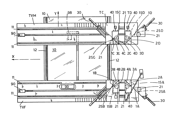
With reference to the drawings, a jig embodied
according to the invention substantially comprises a
bed 10, and two essentially longitudinal carriages
TVF and TVM disposed parallel one with the other,
which are mounted on the bed 10 and in their turn
support four clamp assemblies, arranged in sets of
two: TA-TB and TC-TD, respectively. Two of the four
clamp assemblies TA and TD occupy a fixed position
on their carriage, TVF and TVM respectively, whereas
the remaining two T8 and TC are capable of movement
7 131377~
along horizontal longitudinal tracks 11 afforded by
the top of the same respective carriages.
The first carriage TVF is anchored rigidly to
the fixed bed 10 beneath, whilst the second carriage
05 TVM can be traversed along a pair of transversely
disposed ways 12 afforded by the bed 10 beneath,
displaced parallel with its own axis, to the end of
distancing it from or drawing it toward the first
carriage TVF.
The four clamp assemblies TA, TB, TC and TD,
which are located to coincide with the four corners
of the frame, each comprise a pair of horizontal
triangular rests 3A-4A, 3B-4B, 3C-4C and 3D-4D that
serve to support the members of the frame; the two
rests of each pair are matched together along their
longest angled side, in such a way that this same
side lies parallel with the miter line along which
the frame members 1, 2, 3 and 4 will ultimately be
welded. Each one of the triangular rests 3A, 4A, 3B,
4B, 3C, 4C, 3D and 4D is provided with a relative
upwardly-projecting fence 2SA, lSA, 2SB, lSB, 2SC,
lSC, 2SD and lSD, that serves to check the side of
the relative frame member 1, 4 (rails), 2 and 3
(uprights) and to ensure its alignment through the
transverse dimension (axis 'y') and through the
8 131~7~
longitudinal (axis 'x'), respectively.
Each clamp assembly TA, TB, TC and TD also
comprises a pair of plates lA-2A, lB-2B, lC-2C and
1 D-2D that is located above the relative pair of
05 rests 3A-4A, 3B-4B, 3C-4C and 3D-4D and serves to
clamp the ends of the two relative frame members
aga~inst them until the positioning and welding steps
are completed. The plates are supported by vertical
posts 20, which also support the means 21 by which
the clamp plates are actuated.
It will be observed that the fences denoted 1 SA,
lSB lSC and lSD (see fig 7), all lie parallel with
the horizontal path followed by the frames when
exiting from the jig, and are rigidly associated
with the respective rests 4A, 4B, 4C and 4D, as well
as with the posts 20 supporting the clamp plates 2A,
2B, 2C and 2D; these four fence-and-rest components
can be shifted in relation to the remainder of the
clamp assembly by suitable first actuator means 40,
which distance them from the frame, moving at right
angles to the longitudinal axis 'x', in such a way
as to free it once the welding step is accomplished.
By contrast, the fences denoted 2SA, 2SB, 2SC
and 3SD, which are disposed parallel with axis 'y',
hence transversely to the horizontal exit path
.
9 ` 1313779
followed by the frames, are capable of movement in
relation to the relative rests 3A, 3B, 3C and 3D
which, in this instance, are rigidly associated with
the respective clamp assembly TA, TB, TC and TD.
05 These fences are therefore capable of movement
relative to the clamp assembly, and are operated by
actuator means 30 that shift them between a first
limit position, in which the rails 1 and 4 are
checked, and a second limit position in which the
rails 1 and 4 are left free to move and the fences
themselves remain clear of the transverse dimension
of the frame; accordingly, further frame members
(rails and uprights) can be fed into the jig,
tangentially to the plane occupied by the frame,
without encountering any obstruction along their
path.
RlA and RlD denote a pair of transport elements,
located beneath the uprights 2 and 3 of the frame
and between the two clamp assemblies at either side
TA-TB and TC-TD, which are capable of vertical
movement between a lowered, at-rest limit position,
and a raised, operative position in which contact
occurs with the upright members of the frame by
simple rolling friction; more exactly, such contact
occurs with the uprights 2 and 3 both during the
lO 1313~
step in which these are offered to the first rail 1
and positioned, and during the successive step in
which, clamped between the plates 2B and 2C and the
rests 4B and 4C beneath, they are carried forward by
05 traversing the relative assemblies TB and TC along
the tracks 11 through a prescribed distance that
reflects the longitudinal dimension of the frame.
The step in which the frame members are welded
together is a hot process involving the application
of pressure to the clamp assemblies; experience has
shown that a bead is left on the frame, coincident
with the miter line of the weldment, produced as a
result of the plastic material melting and-filling
the gaps between the paired rest, and clamp plates.
On the underside in particular, material penetrates
between the triangular rests and solidifies, causing
an obstruction when the moment comes to raise the
welded frame and remove it; accordingly, the jig
disclosed is provided with centralizers 60 (fig 6)
that operate within a horizontal plane on the rear
corners of the frame, considered in relation to the
direction of its removal from the jig.
More exactly, the centralizers 60 move through
: paths that converge, and are angled substantially at
45 in relation to axis 'y'; the paths described by
11 ~3~37~
the centralizers 60 do not coincide with the miter
line however, but will be marginally advanced in
relation thereto in order to ensure that the bead
formed on each weldment separates from the
05 corresponding pair of rests 3A-4A, 3B-4B, 3C-4C, and
3D-4D.
The jig thus described operates a regular cycle
of steps, as illustrated in figs 1...6, which may be
summarized as follows:
('far' and 'near' are referred to operator)
A - at the beginning of the cycle, the jig appears
as in fig 1, thus:
-clamp plates in the raised position;
-longitudinal rests 4A, 4B, 4C and 4D and relative
fences lSA, lSB, lSC and lSD spread apart at maximum
distance transversely to axis 'x';
-near transverse fences 2SA and 2SD spread at
maximum distance apart (second limit position);
-far transverse fences 2SB and 2SC drawn together at
minimum distance apart (first limit position), the
relative clamp assemblies TB and TC lying within
arm's reach of the operator to enable positioning of
the first rail 1.
B - With the first rail 1 in position (fig 2), the
operator depresses button Pl at the console 70 to
.
. . :
~137~
12
raise a first pair of locators PB and PC;
- the first actuator means 40 are operated to draw
together the far longitudinal rests 4B and 4C and
their fences lSB and lSC;
05 - the transport elements RlA and RID are raised;
- the operator introduces the two upright frame
members 2 and 3, running them forward against the
relative locators PB and PC.
C - The operator depresses button P2 at the console,
-10 causing the far clamp plates lB, 2B, lC and 2C to
descend toward the relative rests 3B, 4B, 3C and 4C,
gripping the rail 1 and the two uprights 2 and 3,
now mitered together, between them (fig 3);
- the far clamp assemblies TB and TC are traversed
longitudinally along axis 'x' away from the near
assemblies TA and TD through a prescribed distance
(entered previously) marginally greater than the
length of the uprights 2 and 3, whereupon the clamp
plates are raised to release all three members 1, 2
and 3;
- the transport elements RlA and RlD retract, and
two further locators PA and PD are raised;
- the near longitudinal rests 4A and 4D and their
fences lSA and lSD are drawn together;
- the operator positions the second rail 4, offering
13 1~3~7~
it to the locators PA and PD.
D - The operator depresses buttons P3 and P3', with
the result that the two near transverse fences 2SA
and 2SD are moved in by the relative actuators 30
05 (~i9 4);
- the far clamp assemblies TB and TC are positioned
at a distance equal to the longitudinal dimension of
the frame, whilst the moving carriage TVM shifts
toward the fixed carriage TVF (axis 'y'), shortening
the transverse distance between the respective pairs
of assemblies TC-TD and TA-TB to match the length of
the rails 2 and 3;
- all the clamp plates descénd, locking the entire
frame in position.
E - The four corners of the frame are hot welded, in
accordance with prior art methods (fig 5).
F - With the weld effected, the clamp plates are
raised, and the longitudinal rests 4A, 4B, 4C and 4D
drawn apart together with their fences lSA, lSB, lSC
and lSD,
- the far transverse fences 2SB and 2SC retract, and
a number of movements occur simultaneously: the far
clamp assemblies TB and TC are moved further along
axis 'x', parallel with one another, and positioned
at a distance from the near clamps TA and TD that is
l~ 131377~
greater than the length of the frame uprights; the
moving carriage TVM is traversed away from the fixed
carriage TVF, and positioned at a distance greater
than the length of the rails; the centralizers 60
05 are operated.
This final set of coordinated movements ensures,
on the one hand, that the welded frame separates
from the longitudinal fences lSA, lSB, lSC and lSD,
and on the other, that the beads of plastic material
separate from the four pairs of triangular rests by
which the frame is supported.
Only in these conditions, and with the two near
fences 2SA and 2SD spread apart at their maximum
distance either side of axis 'x', does it become
possible to remove the welded frame from the jig,
given that there is no further obstacle to prevent
its being lifted and traversed away from the clamps;
accordingly, cylinders CN will be activated at this
juncture to raise a pair of belt loops NTl and NT2
for the very purpose.
With the belts raised, their drive motors MNTl
and MNT2 are set in motion and the frame is conveyed
away from the jig and onto a roller table. This same
movement of the frame away from the jig will excite
transducers that trigger a general reset of the
l s
1313779
various components in readiness for the next cycle.
In a preferred embodiment of the jig, use will
be made of a micropressor 99 by which all movements
of the different drive systems and actuators can be
05 controlled according to program cycles entered using
a set of keys 81. Such microprocessor control is of
particular importance both in controlling operation
of the first actuator means 40 following the welding
step, to separate the relative triangular rests 4A,
48, 4C and 4D from the beads of plastic léft by the
weld, and in coordinating the operation of second
actuator means 98 (by which the moving carriage TVM
is `traversed, in particular during step F), of third
actuator means 91 (by which the centralizers 60 are
operated), and of the actuator means 90 by which the
far clamp assemblies TB and TC are distanced from
the near clamps TA and TD; only with these movements
faultlessly coordinated can it be ensured that the
longitudinal fences lSA, lSB, lSC and lSD separate
completely from the frame, and by the same token,
that with movement of the post-welding beads neither
impeded nor creating any impediment, the subsequent
lifting movement that precedes ultimate removal of
the frame will not be obstructed.
It will be evident from the foregoing that the
16 ~ 3 ~
jig disclosed is eminently suited to further auto-
mation, for example, the application of an automatic
feeder; adopting the conventional positioning
sequence when assembling frames, in fact, rails and
05 uprights fed automatically to the clamp assemblies
will encounter no obstacles in their path.