Language selection

Search

Patent 1313803 Summary

Third-party information liability

Some of the information on this Web page has been provided by external sources. The Government of Canada is not responsible for the accuracy, reliability or currency of the information supplied by external sources. Users wishing to rely upon this information should consult directly with the source of the information. Content provided by external sources is not subject to official languages, privacy and accessibility requirements.

Claims and Abstract availability

Any discrepancies in the text and image of the Claims and Abstract are due to differing posting times. Text of the Claims and Abstract are posted:

  • At the time the application is open to public inspection;
  • At the time of issue of the patent (grant).
(12) Patent: (11) CA 1313803
(21) Application Number: 605549
(54) English Title: SINGLE CHANNEL BALLOON UTERINE INJECTOR
(54) French Title: DISPOSITIF D'INJECTION UTERINE AVEC TUBE GONFLABLE ET CANAL UNIQUE
Status: Deemed expired
Bibliographic Data
Abstracts

English Abstract


-9-

Abstract of the Disclosure
An apparatus for injection of dye or contrast
medium into a uterine cavity. An elongated member
having a first and a second end and an intermediate
portion has a liquid impervious expandable tube
disposed around it and is sealed on each end thereof to
the exterior thereof. A first fluid passageway extends
from one end of the elongated member to a barrier and
another fluid passageway extends from the other end of
the elongated member to the barrier. A first opening
in the elongated member allows fluid communication
between the first passageway and the inside of the
balloon tube and a second opening in the elongated
member provides fluid communication between the second
fluid passageway and the inside of the balloon tube.
The second opening is substantially smaller in
cross-sectional area than the first opening whereby
fluid pressure applied to the first passageway will
remain substantially higher than the pressure in the
second fluid communication passageway, whereby fluid
pressure within the tube will cause it to expand to
seal against the inner wall of the uterine cavity,
while at the same time fluid will flow sequentially
from the first fluid communication passageway, through
the first opening, through the expanded balloon tube,
through the second opening, through the second
communication passageway and out through a discharge
opening structure on one end of the second fluid
communication passageway.


Claims

Note: Claims are shown in the official language in which they were submitted.


-6-
Claims
I CLAIM:
1. Apparatus for injection of dye or contrast
medium into a uterine cavity comprising:
an elongated member having a first end, a second
end and an intermediate portion between the first and
second ends;
a liquid impervious expandable tube disposed
around said elongated member and being sealed at each
end thereof to the exterior of said elongated member,
said tube extending over said intermediate portion of
said elongated member;
first means for forming a first fluid
communication passageway from said first end to said
intermediate portion of said elongated member;
second means for forming a second fluid
communication passageway from said intermediate portion
to said second end of said elongated member;
said first end of said elongated member being
adapted to receive a source of liquid dye or contrast
medium under pressure;
a first opening in said elongated member, said
first opening being in fluid communication with said
first fluid communication passageway with the inside of
said tube;
a second opening in said elongated member, said
second opening being in fluid communication with said
second fluid communication passageway and with the
inside of said tube;
barrier means disposed on the interior of said
elongated member to prevent direct fluid communication
between said first and second fluid communication
passageway;
discharge means disposed in said second end of
said elongated member for permitting fluid in said
second fluid communication passageway to exit
therethrough; and


-7-
said second opening being substantially smaller in
said cross-sectional area than said first opening
whereby the fluid pressure inside of said tube will be
substantially higher than the pressure in said second
fluid communication passageway whereby the fluid
pressure within the tube will cause it to expand to
seal against the inner wall of the uterine cavity while
at the same time fluid will flow sequentially from the
first fluid communication passageway, through the first
opening r through the expanded tube, through the second
opening, through the second fluid communication
passageway and out the discharge means.
2. The apparatus of claim 1 wherein said
discharge means includes a plurality of holes in the
second end of said elongated member.
3. The apparatus of claim 2 wherein a rounded
plug is disposed in the second fluid communication
passageway of said second end of said elongated member.
4. The apparatus of claim 3 wherein said
elongated member is straight except for being curved on
the second end thereof.
5. Apparatus for injection of dye or contrast
medium into a uterine cavity comprising:
an elongated member having a first end, a second
end and an intermediate portion between the first and
second ends;
a liquid impervious expandable tube disposed
around said elongated member and being sealed at each
end thereof to the exterior of said elongated member,
said tube extending over said intermediate portion of
said elongated member;
first means for forming a first fluid
communication passageway from said first end to said
intermediate portion of said elongated member;
second means for forming a second fluid
communication passageway from said intermediate portion
to said second end of said elongated member;


-8-
said first end of said elongated member being
adapted to receive a source of liquid dye or contrast
medium under pressure;
a first opening in said elongated member, said
first opening being in fluid communication with said
first fluid communication passageway with the inside of
said tube;
a second opening in said elongated member, said
second opening being in fluid communication with said
second fluid communication passageway and with the
first fluid communication passageway;
discharge means disposed in said second end of
said elongated member for permitting fluid in said
second fluid communication passageway to exit
therethrough; and
said second opening being substantially smaller in
said cross-sectional area than said first opening
whereby the fluid pressure inside of said tube will be
substantially higher than the pressure in said second
fluid communication passageway whereby the fluid
pressure within the tube will cause it to expand to
seal against the inner wall of the uterine cavity while
at the same time fluid will flow sequentially from the
first fluid communication passageway, through the first
opening, through the expanded tube, through the second
opening, through the second fluid communication
passageway and out the discharge means.

Description

Note: Descriptions are shown in the official language in which they were submitted.


~ 3~38~3
"Single Channel Balloon Uterine Injector"
Technical Field
The present invention relates generally to a
uterine injector, and more particularly to a single
channel balloon-type uterine injector.
Back~round Art
There are different instruments available for
injection of dye or x-ray contrast medium into the
uterine cavity. In order to seal the vaginal opening
of the uterus texternal os) some of the cannulas have
an acorn which is pushed against the external os and
insures leak proof application. Sometimes, however t
the sealing of the external os fails.
In an attempt to overcome this problem, another
instrument was developed. This instrument consists of
two channels, one for injection of dye or x-ray
contrast medium, and the second for inflating a balloon
inside the uterine cavity. This structure seals the
external os and prevents leaking. The disadvantages of
the cannula with balloon instrument is its cumbersome
construction and its high cost.
Disclosu~e of the Invention
~ .
- The present invention relates to an apparatus for
injection of dye or contrast medium into a uterine
cavity. An elongated member having a first and a
second end and an intermediate portion has a liquid
impervious expandable tube disposed around it and is
sealed on each end thereof to the exterior thereof. A
first fluid passageway extends from one end of the
elongated member to a barrier and another fluid


.
., '

.


;,

,

-2- 13~3~3
passageway extends from the other end of the elongated
member to the barrier. A first opening in the
elongated member allows fluid communication between the
first passageway and the inside of the balloon tube and
a second opening in the elongated member provides fluid
communication between the second fluid passageway and
the inside of the balloon tube.
The second opening is substantially smaller in
cross-sectional area than the first opening whereby
fluid pressure applied to the first passageway will
remain substantially higher than the pressur0 in the
second fluid communication passageway, whereby fluid
pressure within the tube will cause it to expand to
seal against the inner walL of the uterine cavity,
while at the same time fluid will flow sequentially
from the first fluid communication passageway, through
the first opening, through the expanded tube, through
the second opening, through the second communication
passageway and out through a discharge opening
structure on one end of the second fluid communication
passageway.
An object of the present invention is to provide
an improved uterine injector.
A further object of the present invention is to
provide an improved uterine injector which is simpler
to use than the prior art uterine injectors.
A further object of the present invention is to
provide a uterine injector which is dependable to use
and which is economical to produce.
Other objects, advantages, and novel features of
the present invention will become apparent from the
foilowing detailed description of the invention when
considered in conjunction with the accompanying
- drawings.
Brief Description of the Drawings
-
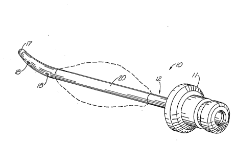
Fig. 1 is a perspective view of a single cha~nel
balloon uterine injector apparatus constructed in

~313~03
--3--
accordance with the present invention and showing in
dashed lines how the balloon-l.ike tube can be expanded;
Fi~. 2 is a top view of the uterine injector of
Fig. l;
Fig. 3 is a cross sectional view taken along line
3-3 of Fig. 2;
Fig. 4 is a view taken along line 4-4 of Fig. 2;
Fig. 5 is an enlarged cross sectional view similar
to Fig. 3 but showing the apparatus when a high
.lO pressure fluid is connected to one end of the elongated
member, illustrating how the balloon will inflate and
the fluid will flow; and
Fig. 6 is a somewhat cross sectional view of a
uterine cavity showing the uterine injector in its
operative position wherein the balloon tube is expanded
to seal against the inner wall of the uterine cav.ity,
` while at the same~time fluid is flowing into the
uterine cavity.
Fig. 7 is a cross sectional view like Fig. 5, but
2~ showing an alternate embodiment;
Best Mode for Carrying Out the Invention
Referring now to the drawings wherein like
reference numerals designate identical or corresponding
. parts throughout the several views, Fig. l shows a
; . 25 uterine injector apparatus (lO) constructed in
accordance with the present invention. Attachment
. ~ll), which fits inside the head of a Valtchev uterine
mobilizer, connects a source of li~uid dye or liquid
x-ray contrast medium to a source of such dye or x-ray
3Q medium under high pressure.
The attachment (113 is in fluid communication with
an elongated member (12). A first fluid communication
passageway ~13) extends from the passageway (14) in the
attachment (ll) to a barrier (15). A second fluid
communication passageway (16) extends from the barrier
(15) to the other end of the elongated member (12).
The extreme other end of the ~longated member (123 has

~ ~3~3~3
a plug (17) in the end thereof to force liquid through
openings (18). The plug ~17) also causes a smooth end
on the elongated member ~12) to prevent damage to the
patient.
The passageway ~13) has a sidewall opening (23)
therein and the passageway (16) has an opening (26)
therein. A tubular balloon-like member l20) ia bonded
in a groove to the elongated member ~12) at each end
thereof as can readily be seen in Fig. 5, but the
center portion of the tube ~20) is not bonded to the
elongated member (12). The elongated tube t20) is of
course sealed and is imperforate to the passage of
fluids therethrough. It can be made o~ silicone rubber
or the like.
In operation, after the cannula is inserted into
the uterine cavity to the position shown in Fig. 6, a
dye or x-ray contrast medium (21) is injected through
the passageway (13). The fluid (21) enters the balloon
cavity through the opening (23) and distends the
balloon to the position shown in Fig. 60
The distended balloon or tube (20) seals the exit
from the uterine cavity ~22). The fluid (21) then
enters from the balloon cavity (24) (Fig. 5) through a
very small opening (26~, which is several times smaller
than the cross sectional size of the opening (23), and
then the flow goes into the passageway (16) and out
through sidewall openings (18)v where it enters the
uterine cavity and the the fallopian tubes.
If there is a constant flow of fluid through the
3~ opening (23), the pressure inside the balloon (20) will
be higher than in the uterine cavity (22). This is due
to the resistance created by the smaller opening (26)
on the fluid flowing from the balloon cavity ~24) to
the passageway ~16). When the injection of fluid
ceases, the pressure in the balloon drops and its
sealing effect diminishes.
;

~313~1~3
--5--
In its preferred embodiment, the opening ~26) has
a 0.1 mm diameter round opening and the opening (23)
has a diameter of 2.0 mm in a round opening~ A 20 ml
syringe is used to inject the fluid into the passageway
(13).
The Fig. 7 embodiment 10' operates just like
embodiment 10 except that opening 26' communicates
passageway 16 directly with passageway 13. The
diameter of 26' is much smaller than opening 23 so that
it forms a restriction so that the balloon 20 will
; 10 inflate as flow goes through passageway 26'.
Accordingly, it will be appreciated that the
preferred embodiment disclosed herein does indeed
accomplish the aforementioned objects. Obviously, many
modifications and variations of the present invention
are possible in light of the above teachings. It is
therefore to be understood that, within the scope of
the appended claims, the invention may be practiced
otherwise than as specifically described.

Representative Drawing
A single figure which represents the drawing illustrating the invention.
Administrative Status

For a clearer understanding of the status of the application/patent presented on this page, the site Disclaimer , as well as the definitions for Patent , Administrative Status , Maintenance Fee  and Payment History  should be consulted.

Administrative Status

Title Date
Forecasted Issue Date 1993-02-23
(22) Filed 1989-07-13
(45) Issued 1993-02-23
Deemed Expired 2002-02-25

Abandonment History

There is no abandonment history.

Payment History

Fee Type Anniversary Year Due Date Amount Paid Paid Date
Application Fee $0.00 1989-07-13
Maintenance Fee - Patent - Old Act 2 1995-02-23 $50.00 1995-04-18
Maintenance Fee - Patent - Old Act 3 1996-02-23 $50.00 1995-12-08
Maintenance Fee - Patent - Old Act 4 1997-02-24 $250.00 1997-12-30
Maintenance Fee - Patent - Old Act 5 1998-02-23 $75.00 1997-12-30
Maintenance Fee - Patent - Old Act 6 1999-02-23 $75.00 1998-12-10
Maintenance Fee - Patent - Old Act 7 2000-02-23 $75.00 1999-01-20
Owners on Record

Note: Records showing the ownership history in alphabetical order.

Current Owners on Record
VALTCHEV, KONSTANTIN LAZAROV
Past Owners on Record
None
Past Owners that do not appear in the "Owners on Record" listing will appear in other documentation within the application.
Documents

To view selected files, please enter reCAPTCHA code :


To view images, click a link in the Document Description column. To download the documents, select one or more checkboxes in the first column and then click the "Download Selected in PDF format (Zip Archive)" or the "Download Selected as Single PDF" button.

List of published and non-published patent-specific documents on the CPD .

If you have any difficulty accessing content, you can call the Client Service Centre at 1-866-997-1936 or send them an e-mail at CIPO Client Service Centre.


Document
Description 
Date
(yyyy-mm-dd) 
Number of pages   Size of Image (KB) 
Drawings 1993-11-10 3 78
Claims 1993-11-10 3 129
Abstract 1993-11-10 1 41
Cover Page 1993-11-10 1 13
Description 1993-11-10 5 210
Representative Drawing 2000-08-11 1 12
Fees 1997-12-30 4 121
Correspondence 2000-11-27 2 98
Correspondence 2001-11-26 3 223
Fees 1998-12-10 1 75
Correspondence 2001-03-26 3 126
Fees 1998-02-02 1 42
Office Letter 1989-07-13 1 44
PCT Correspondence 1989-08-25 1 18
Prosecution Correspondence 1990-08-07 10 386
Examiner Requisition 1990-07-17 1 55
Correspondence 1997-12-30 1 17
Correspondence 1995-12-08 1 59
Correspondence 1995-04-18 1 46