Language selection

Search

Patent 1314033 Summary

Third-party information liability

Some of the information on this Web page has been provided by external sources. The Government of Canada is not responsible for the accuracy, reliability or currency of the information supplied by external sources. Users wishing to rely upon this information should consult directly with the source of the information. Content provided by external sources is not subject to official languages, privacy and accessibility requirements.

Claims and Abstract availability

Any discrepancies in the text and image of the Claims and Abstract are due to differing posting times. Text of the Claims and Abstract are posted:

  • At the time the application is open to public inspection;
  • At the time of issue of the patent (grant).
(12) Patent: (11) CA 1314033
(21) Application Number: 582659
(54) English Title: SLIT LAMP INSTRUMENT WITH FILL-IN ILLUMINATION
(54) French Title: DISPOSITIF D'ECLAIRAGE LINEAIRE AVEC ECLAIRAGE D'APPOINT
Status: Deemed expired
Bibliographic Data
(52) Canadian Patent Classification (CPC):
  • 240/183
(51) International Patent Classification (IPC):
  • A61B 3/10 (2006.01)
  • A61B 3/135 (2006.01)
(72) Inventors :
  • MULLER, ORTWIN (Germany)
  • GEISS, GUNTER (Germany)
  • STOPAR, VIKTOR (Germany)
(73) Owners :
  • MULLER, ORTWIN (Not Available)
  • GEISS, GUNTER (Not Available)
  • STOPAR, VIKTOR (Not Available)
  • CARL-ZEISS-STIFTUNG, A FOUNDATION ESTABLISHED UNDER THE LAWS OF GERMANY TRADING AS CARL ZEISS (Germany)
(71) Applicants :
(74) Agent: ROBIC
(74) Associate agent:
(45) Issued: 1993-03-02
(22) Filed Date: 1988-11-09
Availability of licence: N/A
(25) Language of filing: English

Patent Cooperation Treaty (PCT): No

(30) Application Priority Data:
Application No. Country/Territory Date
G 87 14 962.1 Germany 1987-11-10

Abstracts

English Abstract


ABSTRACT OF THE DISCLOSURE


Slit lamp instrument consisting of a stereomi-
croscope, a slit illumination device rotatable about a
vertical axis, a fill-in illumination device and a
mechanical system coupling the stereomicroscope and
illumination devices. The fill-in illumination device can
be rotated about a vertical axis independently of other
instrument components.


Claims

Note: Claims are shown in the official language in which they were submitted.


The embodiment of the invention in which an exclusive
property or privilege is claimed are defined as follows:

1. Slit lamp instrument consisting of a stereomicroscope, a
slit illumination device rotatable about a vertical axis, a
fill-in illumination device and a mechanical system coupling
the stereomicroscope and illumination devices, characterized
by the fact that the fill-in illumination device can be
rotated about a vertical axis independently of other
instrument components.

2, Slit lamp instrument according to claim 1, characterized
by the fact that the axis of rotation of the fill-in
illumination device is isocentric to the axis of rotation of
the slit illumination device.

3. Slit lamp instrument according to claim 2, characterized
by the fact that the fill-in illumination device is
connected to the instrument's mechanical system below the
head of the patient.

4. Slit lamp instrument according to claim 2, characterized
by the fact that the fill-in illumination device is
connected to the instrument's mechanical system above the
head of the patient.

- 5 -


Description

Note: Descriptions are shown in the official language in which they were submitted.


13~3~
-2-

Description:

Slit lamp instrument with fill-in illumination

The present invention relates to a slit lamp instrument
consisting of a stereomicroscope, a slit illumination
device rotatable about a vertical axis, a fill-in
illumination device and a mechanical system coupling the
stereomicroscope and the illumination devices.

Slit lamp instruments whi.ch feature a fill-in illumination
device in addition to the slit illumination device are
known as photo slit lamps and described, for example, in
the brochure "Ocular Examination with the Slit Lamp",
published by Carl Zeiss, Oberkochen. A drawback of these
known slit lamps is that the angle of incidence of the
fill-in illumination device can only be changed if this
illumination device is rotated together with the stereo-
microscope about the axis of rotation of the mechanical
system, about which the slit illumination device is also
rotatable. ~ `
: ' :
; The plane of the slit image and the focal plane of the
microscope contain the virtual extension line of this axis
of rotation. Using an instrument base, this plane can be
moved in the X, Y and Z directions to the examination area
on the eye. The mechanical mount of this common axis for
rotation for the~slit illumination device and for the
stereomicroscope can be arranged above or below the head of
the~patient, depending on the model of the slit lamp in-
strument.

The object of the present invention is to provide known
slit lamp instruments with an additional illumination
device whose direction of incidence can be changed inde-
pendently of other instrument components and of the slit
illumination device.


:~:
. . :


: .

~31~33


According to the present invention there .is provided a slit
lamp ins-trument consisting of a stereomicroscope, a slit
illumlna-tion device rotatable abo~lt a vertical axis, a fill-
in illumination device and a mechanical system coupling the
stereomicroscope and illumination devices, characterized by
the fact that the fill-in illumination device can be rotated
about a vertical axis independently of other instrument
components.

Preferably, the axis of rotation of the fill-in illumination
device is isocentric to the axis of rotation of the slit
illumination device.

Preverably, the fill-in illumination device may be connected
to the instrument's mechanical system below or above the
; head of the patient.

The particular advantage of the invention lies in the fact
; ~ that the axes of the slit illumination device and the fill-
20 ~ in illumination device can be arranged isocentrically to
each other which ensures that the luminous spot of the
additional illumination will always be situated in the
; focal plane of the slit illumination~dsvice and the
stereomicroscope. Another advantage of the invention lies
~ n the possibility of mounting a laser light source in
place of the fill-in illumination device. Such a laser slit
lamp wi~ll make it possible to select the direction oE the
laser beam independently of the viewing direction of the
mLcroscope and the di~rection of the slit illumination.
30~ ~
:Suitable embodiments of the invention are shown in the
drawings and will be described ~n detail below, in which
~ :


: :

. .

~3~033

- 3a -


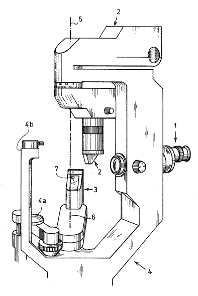
Fig. t is an Lllustration in perspective of a slit lamp
instrument with an additional fill-in lllumination
device rotatabls about a vertical axis;


Fig. 2 is a section of the slit lamp instrument shown in
Fig. l;

Fig. 3 is a section o a laser slit lamp;

Fig. 4 is sectLon of a slit lamp instrument in which the
fill-in illumination device is mounted above the
eye of the patient.


/


:` /
/
~ 25~ /
~ ; /


~ :30~ /

: ~ ~
C


~: :

13~33

-4-

In Fig. 1, (1) designates a stereomicroscope, (2) a slit
illumatlon device, (3) a fill-in illumination device and
(4) the instrument's mechanical system. (4a) designates the
chirlrest, (4b) the device for holding the headrest for the
patient. The illumination devi.ce (3) is rotatable about the
axis (6) which is isocentric to the axis of rotation (5).
~he illumination device (3) is sealed with a window (7) for
the transmission oE the illumination rays.

The section in Fig. 2 shows the optical components for the
slit lamp instrument. They are not designated as they are
generally accepted as prior art. In this illustration, (8)
designates the patient's eye, (9) the observer's eye. (10)
designates a photographic system for documentation to which
the observation beam can be directed via hinged mirror
(11), if needed. Furthermore, the same designations have
been used for the same components as in Fig. 1. ~he section
in Fig. 3 shows the same setup as Fig. 2 with the exception
of the ].aser light source (12). In this embodiment, the
radiation of the laser light source (12) can be directed
for the purpose of therapy to the patient's eye instead of
:a fill-in illumination.
:
The section in Fig. 4 shows a slit lamp instrument with a
mechanical system (14), in which the slit illumination
device (22) is mounted below the patient's eye (8) and the
fill-in illumination device (3) above the patient's eye
(8). The axis of rotation (16) of the fill-in illumination
device is isocentric to the axis of rotation of the slit
illumination device.


::
: ~ ::: :
::


. '

.

, , .
Representative Drawing
A single figure which represents the drawing illustrating the invention.
Administrative Status

For a clearer understanding of the status of the application/patent presented on this page, the site Disclaimer , as well as the definitions for Patent , Administrative Status , Maintenance Fee  and Payment History  should be consulted.

Administrative Status

Title Date
Forecasted Issue Date 1993-03-02
(22) Filed 1988-11-09
(45) Issued 1993-03-02
Deemed Expired 1995-09-04

Abandonment History

There is no abandonment history.

Payment History

Fee Type Anniversary Year Due Date Amount Paid Paid Date
Application Fee $0.00 1988-11-09
Registration of a document - section 124 $0.00 1989-02-02
Owners on Record

Note: Records showing the ownership history in alphabetical order.

Current Owners on Record
MULLER, ORTWIN
GEISS, GUNTER
STOPAR, VIKTOR
CARL-ZEISS-STIFTUNG, A FOUNDATION ESTABLISHED UNDER THE LAWS OF GERMANY TRADING AS CARL ZEISS
Past Owners on Record
None
Past Owners that do not appear in the "Owners on Record" listing will appear in other documentation within the application.
Documents

To view selected files, please enter reCAPTCHA code :


To view images, click a link in the Document Description column. To download the documents, select one or more checkboxes in the first column and then click the "Download Selected in PDF format (Zip Archive)" or the "Download Selected as Single PDF" button.

List of published and non-published patent-specific documents on the CPD .

If you have any difficulty accessing content, you can call the Client Service Centre at 1-866-997-1936 or send them an e-mail at CIPO Client Service Centre.


Document
Description 
Date
(yyyy-mm-dd) 
Number of pages   Size of Image (KB) 
Representative Drawing 2000-08-11 1 20
Drawings 1993-11-10 4 185
Claims 1993-11-10 1 33
Abstract 1993-11-10 1 26
Cover Page 1993-11-10 1 29
Description 1993-11-10 4 160
PCT Correspondence 1992-11-19 1 22
Prosecution Correspondence 1990-12-06 2 50
Examiner Requisition 1990-08-24 1 34