Language selection

Search

Patent 1314148 Summary

Third-party information liability

Some of the information on this Web page has been provided by external sources. The Government of Canada is not responsible for the accuracy, reliability or currency of the information supplied by external sources. Users wishing to rely upon this information should consult directly with the source of the information. Content provided by external sources is not subject to official languages, privacy and accessibility requirements.

Claims and Abstract availability

Any discrepancies in the text and image of the Claims and Abstract are due to differing posting times. Text of the Claims and Abstract are posted:

  • At the time the application is open to public inspection;
  • At the time of issue of the patent (grant).
(12) Patent: (11) CA 1314148
(21) Application Number: 608582
(54) English Title: FAN FOLDED ABRASIVE DISCS
(54) French Title: DISQUES ABRASIFS PLIES EN ACCORDEON
Status: Deemed expired
Bibliographic Data
(52) Canadian Patent Classification (CPC):
  • 51/155
(51) International Patent Classification (IPC):
  • B24D 11/00 (2006.01)
(72) Inventors :
  • FRY, RICHARD L. (United States of America)
  • BERGSRUD, GERALD L. (United States of America)
  • WELDON, JAMES A. (United States of America)
  • MALAND, RUSSELL J. (United States of America)
(73) Owners :
  • MINNESOTA MINING AND MANUFACTURING COMPANY (United States of America)
(71) Applicants :
(74) Agent: SMART & BIGGAR
(74) Associate agent:
(45) Issued: 1993-03-09
(22) Filed Date: 1989-08-17
Availability of licence: N/A
(25) Language of filing: English

Patent Cooperation Treaty (PCT): No

(30) Application Priority Data:
Application No. Country/Territory Date
245,462 United States of America 1988-09-06

Abstracts

English Abstract


Abstract of the Disclosure

A concatenation of circular abrasive discs each
having a layer of abrasive material on a first surface, and
means on a second surface for releasably attaching said
discs to a drive member. The discs are attached to two
adjacent discs at opposite edges by two narrow tabs along
each edge spaced by at least 0.32 centimeter (1/8 inch)
along the edge and generally equally spaced on opposite
sides of a center line extending between the centers of the
attached discs. Also the discs are separated between the
tabs and the tabs are folded to position abrasive discs in a
stack within a container with each abrasive disc in the
stack having its layer of abrasive against the layer of
abrasive of one adjacent disc, and its means for attaching
adjacent the means for attaching of the other adjacent disc.


Claims

Note: Claims are shown in the official language in which they were submitted.


-7-
The embodiments of the invention in which an exclusive
property or privilege is claimed are defined as follows:

1. A concatenation of circular abrasive discs each
including a backing having first and second major surfaces,
a layer of abrasive material on said first surface, and a
multiplicity of loops projecting from said second surface by
which said discs may be releasably attached to a drive
member having hooks adapted to releasably engage the loops,
said discs being cut from a single sheet of stock and each
disc being attached to two adjacent discs at opposite edges
by two narrow tabs along each edge spaced by at least about
0.32 centimeter (1/8 inch) along said edge and generally
equally spaced on opposite sides of a center line extending
between the centers of the attached discs, said discs being
separated between said tabs and said tabs being folded to
position said abrasive discs in a stack with each abrasive
disc within the stack having its layer of abrasive material
against the layer of abrasive material of one adjacent disc,
and its loops against the loops of the other adjacent disc.

2. A concatenation of circular abrasive discs
according to claim 1 wherein said two narrow tabs along each
edge are spaced by about 1.6 centimeter (5/8 inch) and are
each less than about 0.16 centimeter (1/16 inch) wide.

3. A concatenation of circular abrasive discs
according to claim 1 wherein each disc is attached to two
adjacent discs at opposite edges by only said two narrow
tabs along each edge, said two tabs are spaced by about 1.6
centimeter (5/8 inch) and are each less than about 0.16
centimeter (1/16 inch) wide.

4. In combination, a concatenation of circular
abrasive discs each including a backing having first and
second surfaces, a layer of abrasive material on said first
surface, and a multiplicity of loops projecting from said
second surface by which said discs may be releasably


-8-
attached to a drive member having hooks adapted to
releasably engage the loops, said discs being cut from a
single sheet of stock and each disc being attached to two
adjacent discs at opposite edges by two narrow tabs along
each edge spaced by at least 0.32 centimeter (1/8 inch)
along said edge and generally equally spaced on opposite
sides of a center line extending between the centers of the
attached discs, said discs being separated between said tabs
and said tabs being folded to position said abrasive discs
in a stack with each abrasive disc in the stack having its
layer of abrasive against the layer of abrasive of one
adjacent disc, and its loops against the loops of the other
adjacent disc; and a container enclosing said stack of
discs, said container having a bottom wall supporting the
bottom disc in said stack, and side walls projecting from
said bottom wall along the edges of the discs in said stack.

5. A combination according to claim 4 wherein
said two narrow tabs along each edge are spaced by about 1.6
centimeter (5/8 inch) and are each less than about 0.16
centimeter (1/16 inch) wide.

6. A combination according to claim 4 wherein
each disc is attached to two adjacent discs at opposite
edges by only said two narrow tabs along each edge, said two
tabs are spaced by about 1.6 centimeter (5/8 inch) and are
each less than about 0.16 centimeter (1/16 inch) wide.

7. A concatenation of circular abrasive discs each
including a backing having first and second major surfaces,
a layer of abrasive material on said first surface, and
means on said second surface for releasably attaching said
discs to a drive member, said discs being cut from a single
sheet of stock and each disc being attached to two adjacent
discs at opposite edges by two narrow tabs along each edge
spaced by at least about 0.32 centimeter (1/8 inch) along
said edge and generally equally spaced on opposite sides of

-9-
a center line extending between the centers of the attached
discs, said discs being separated between said tabs and said
tabs being folded to position said abrasive discs in a stack
with each abrasive disc within the stack having its layer of
abrasive material against the layer of abrasive material of
one adjacent disc, and its means for releasably attaching
adjacent the means for releasably attaching of the other
adjacent disc.

8. A concatenation of circular abrasive discs
according to claim 7 wherein said two narrow tabs along each
edge are spaced by about 1.6 centimeter (5/8 inch) and are
each less than about 0.16 centimeter (1/16 inch) wide.

9. A concatenation of circular abrasive discs
according to claim 7 wherein each disc is attached to two
adjacent discs at opposite edges by only said two narrow
tabs along each edge, said two tabs are spaced by about 1.6
centimeter (5/8 inch) and are each less than about 0.16
centimeter (1/16 inch) wide.

10. In combination, a concatenation of circular
abrasive discs each including a backing having first and
second surfaces, a layer of abrasive material on said first
surface, and means on said second surface for releasably
attaching said discs to a drive member, said discs being cut
from a single sheet of stock and each disc being attached to
two adjacent discs at opposite edges by two narrow tabs
along each edge spaced by at least 0.32 centimeter (1/8
inch) along said edge and generally equally spaced on
opposite sides of a center line extending between the
centers of the attached discs, said discs being separated
between said tabs and said tabs being folded to position
said abrasive discs in a stack with each abrasive disc in
the stack having its layer of abrasive against the layer of
abrasive of one adjacent disc, and its means for attaching
adjacent the means for attaching of the other adjacent disc;


-10-
and a container enclosing said stack of discs, said
container having a bottom wall supporting the bottom disc in
said stack, and side walls projecting from said bottom wall
along the edges of the discs in said stack.

11. A combination according to claim 10 wherein
said two narrow tabs along each edge are spaced by about 1.6
centimeter (5/8 inch) and are each less than about 0.16
centimeter (1/16 inch) wide.

12. A combination according to claim 10 wherein
each disc is attached to two adjacent discs at opposite
edges by only said two narrow tabs along each edge, said two
tabs are spaced by about 1.6 centimeter (5/8 inch) and are
each less than about 0.16 centimeter

Description

Note: Descriptions are shown in the official language in which they were submitted.


1 3 1 4 1 48
Fan Folded Abrasive Discs

Technical Field
The present invention relates to concatenations of
5 abrasive discs, the means by which the discs are attached
together, and the disposure of the discs in a container
prior to use.


Background Art
Various approaches described in EPO Patent No. EP
0 021 348 and in U.S. Patents No.s 3,225,916, 3,912,142 and
4,245,765 have been used to form concatenations of abrasive
discs and store the discs in containers prior to use. The
discs described in these patents are releasably attached or
15 adhered to a drive member by a layer of pressure sensitive
adhesive on the side of the disc opposite the layer of
abrasive. The discs described in EPO Patent No. EP 0 021
348 and in U.S. Patent No. 3,225,916 have release liners
over their layers of pressure sensitive adhesive and are
20 stored prior to use by having a strip or lengths of adhesive
coated tape adhered to the release liners of a plurality of
the discs with the discs spaced along the tape, and either
rolling the thus attached discs into a coil or folding the
tape between certain of the discs to position the abrasive
25 discs in a stack with each abrasive disc in the stack having
its layer of abrasive against the layer of abrasive of one
adjacent disc, and its adhesive covering release liner
adjacent the adhesive covering release liner of the other
adjacent disc; and enclosing the coil or stack of attached
30 discs in a container. The discs described in U.S. Patents
Nos. 3,912,142 and 4,245,765 have been cut from a single
sheet of stock and each have been attached to two adjacent
discs along opposite edges by one wide tab or a series of
narrow tabs along each edge so that the discs can be
35 separated by cutting or breaking the tabs and the discs are
rolled into a coil positioned in a container having means
for facilitating breaking or cutting the tabs so that single

1 3 1 4 1 ~
--2--
discs may be removed from the coil as needed. Also, such
discs having release liners over their layers of adhesive
have been stored in a stack in a container with the abrasive
of each disc in the stack adjacent the liner of the adjacent
5 disc.
While such approaches are acceptable for storing
discs adapted to be attached to a drive member by layers of
pressure sensitive adhesive, none of these approaches is
acceptable for discs which are adapted to be attached to a
10 drive member by a multiplicity of loops projecting from the
side of the disc opposite the layer of abrasive. Individual
discs placed in a box with the loops on one disc against the
abrasive of another are hard to stack one above the other
because the loops will not slide across the abrasive. The
15 use of adhesive coated tape to attach discs together would
add expense and could compress and be difficult to separate
from the loops. Rolling such discs attached together at
their edges into a coil tends to flatten the loops and
abrasive discs having coating of heavy grits can not be
20 wound on a small core (which is also a problem for pressure
sensitive adhesive coated discs).

Disclosure of Invention
The present invention provides a concatenation of
25 abrasive discs disposed in a container that can have loops
by which said discs may be releasably attached to a drive
member having hooks adapted to releasably engage the loops,
which discs are disposed in the container so that the loops
are not crushed or engaged with the abrasive and can move
30 relative to each other while in face to face engagement to
facilitate proper alignment of the discs into a stack in the
; container.
According to the present invention there is
provided a concatenation of circular abrasive discs each
35 including a layer of abrasive material on a first ~urface of
a backing and means on a second surface for releasably
attaching the discs to a drive member (which can be a

..

_3_ 1~1414~
multiplicity of projecting 1Oo2s or a layer of pressure
sensitive adhesive covered by a release liner) which discs
are cut from a single sheet of stock and are each attached
to two adjacent discs along opposite edges by two narrow
5 tabs along each edge spaced by at least 0.32 centimeter (1/8
inch) and preferably by about 0.16 centimeter (1/8 inch)
along the edge, which tabs are generally equally spaced on
opposite sides of a center line extending between the
centers of the attached discs. The discs are separated
10 between the tabs and the tabs are folded to position the
abrasive discs in a stack with each abrasive disc in the
stack having its layer of abrasive against the layer of
abrasive of one adjacent disc, and its loops or liner
covered adhesive against the loops or liner covered adhesive
15 of the other adjacent disc, which is particularly useful
with discs having loops as it allows the discs to slide
relative to each other so that they can more easily be
stacked. The stack of sheets can be enclosed in a container
which has a bottom wall supporting the bottom disc in the
20 stack, and side walls projecting from the bottom wall along
the edges of the discs in the stack, and a top structure
that facilitated dispensing the discs individually from the
container.

25 Brief Description of Drawing
The present invention will be further described
with reference to the accompanying drawing wherein like
reference numerals refer to like parts in the several views,
and wherein:
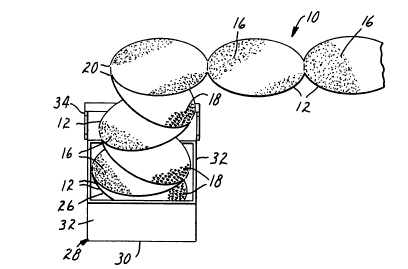
Figure 1 is a perspective view of a concatenation
of circular abrasive discs according to the present
invention; and
Figure 2 is an enlarged fragmentary view of three
discs from the concatenation of Figure 1 with one disc
35 broken away from the other two which illustrates connecting
tabs between the discs.


'

_4_ 1 31 41 4~
Detailed Description
Referring now to Figure 1 of the drawing, there is
shown a concatenation of circular abrasive discs 12
according to the present invention, which concatenation is
5 generally designated by the reference numeral 10.
Generally each of the circular abrasive discs 12
includes a backing having first and second major surfaces, a
layer of abrasive material 16 on its first surface, and a
multiplicity of loops 18 projecting from its second surface
10 by which the disc 12 may be releasably attached to a drive
member (not shown) having hooks adapted to releasably engage
the loops 18. The discs 12 are cut from a single sheet of
stock with each of the discs 12 being attached to two
adjacent discs 12 along opposite edges by two narrow tabs 20.
15 along each edge. The two tabs 20 along each edge are spaced
by at least about 0.32 centimeter (1/8 inch) and preferably
by about 1.6 centimeter (5/8 inch), and are generally
equally spaced on opposite sides of an imaginary center line
(illustrated in Figure 2 by dotted line 22) extending
20 between the centers of the attached discs 12. The discs 12
are separated between the tabs 20. Also, preferably each
pair of adjacent discs 12 is attached by only two tabs 20,
each of which tabs 20 is less than about 0.16 centimeter
(1/16 inch) wide~ Such spacing, separation of the discs 12
25 between the tabs 20, and tab width allows the tabs 20 to
easily bend or fold and reliably form a hinge that will
position the abrasive discs 12 in a stack 26 with each
abrasive disc 12 in the stack 26 having its layer of
abrasive material 16 against the layer of abrasive material
30 16 of one adjacent disc 12, and its loops 18 against the
loops 18 of the other adjacent disc 12. Also, this
engagement of similar surfaces of the discs 12 allows the
discs 12 to slide sideways relative to each other if needed
so that they can more easily be stacked.
The stack 26 of discs can be enclosed in a
cardboard container 28 which has a bottom wall 30 supporting
the bottom disc 12 in the stack 26, side walls 32 projecting

131 41 A8

from the bottom wall 30 along the edgec of the discs 12 ln
the stack 26, and which has a top structure such as the
conventional hinged cover 34 illustrated that facilitates
di~pensing the discs 12 one by one from the stack 26.
The sheet of stock from which the abrasive discs
12 and their connecting tabs 20 are cut can be formed in any
known manner including that described in U.S. Patent No.
4,609,581.
The abrasive discs 12 and their connecting tabs
10 20 can be cut from the sheet of stock in a known manner by a
rotary die assembly. It has been found that concatenations
of cut discs 12 and connecting tabs 20 formed by such dies
that have layers of larger size abrasive material (e.g., 40
or 36 grit) can be guided into the container 28 90 that the
15 discs 12 fold back and forth on themselves to form the stack
26 described above. It appears, however, that
concatenations of cut discs 12 and connecting tabs 20 formed
by ~uch dies that have layers of smaller size abrasive
material (e.g., 180 grit) will have to have the appropriate
20 bends started in the tabs 20 as by a pair of gear like
structures that guide the concatenation therebetween before
the discs 12 will fold back and forth to form such a stack
26 when they are guided into the container 28.
Attachment between discs provided by only two tabs
25 20 spaced as indicated above with the discs 12 separated
between the tabs 20 and the tab widths limited to allow the
tabs 20 to easily bend or fold and reliably form a hinge so
that the discs can be stacked is also useful for discs in
which the ~eans on a second surface for releasably attaching
30 the discs to a drive member is a layer of pre~sure sensitive
adhesive covered by a release liner rather than a
multiplicity of projecting loops. The tabs can then be
folded to position the abrasive discs in the stack with each
abrasive disc in the stack having its layer of abrasive
35 against the layer of abra~ive of one adjacent disc, and its
liner covered adhesive against the liner covered adhesive of
the other adjacent disc.


.....

-6- 1314148
The present invention has now been described with
reference to two embodiments thereof. It will be apparent
to those skilled in the art that many changes can be made in
the embodiments described without departing from the scope
S of the present invention. Thus the scope of the present
invention should not be limited to the structures described
in this application, but only by structures described by the
language of the claims and the equivalents of those
structures.


.~

:,


.,


:''

, .

Representative Drawing
A single figure which represents the drawing illustrating the invention.
Administrative Status

For a clearer understanding of the status of the application/patent presented on this page, the site Disclaimer , as well as the definitions for Patent , Administrative Status , Maintenance Fee  and Payment History  should be consulted.

Administrative Status

Title Date
Forecasted Issue Date 1993-03-09
(22) Filed 1989-08-17
(45) Issued 1993-03-09
Deemed Expired 1999-03-09

Abandonment History

There is no abandonment history.

Payment History

Fee Type Anniversary Year Due Date Amount Paid Paid Date
Application Fee $0.00 1989-08-17
Registration of a document - section 124 $0.00 1989-11-10
Maintenance Fee - Patent - Old Act 2 1995-03-09 $100.00 1995-02-10
Maintenance Fee - Patent - Old Act 3 1996-03-11 $100.00 1996-02-20
Maintenance Fee - Patent - Old Act 4 1997-03-10 $100.00 1997-02-21
Owners on Record

Note: Records showing the ownership history in alphabetical order.

Current Owners on Record
MINNESOTA MINING AND MANUFACTURING COMPANY
Past Owners on Record
BERGSRUD, GERALD L.
FRY, RICHARD L.
MALAND, RUSSELL J.
WELDON, JAMES A.
Past Owners that do not appear in the "Owners on Record" listing will appear in other documentation within the application.
Documents

To view selected files, please enter reCAPTCHA code :


To view images, click a link in the Document Description column. To download the documents, select one or more checkboxes in the first column and then click the "Download Selected in PDF format (Zip Archive)" or the "Download Selected as Single PDF" button.

List of published and non-published patent-specific documents on the CPD .

If you have any difficulty accessing content, you can call the Client Service Centre at 1-866-997-1936 or send them an e-mail at CIPO Client Service Centre.


Document
Description 
Date
(yyyy-mm-dd) 
Number of pages   Size of Image (KB) 
Drawings 1993-11-30 1 22
Claims 1993-11-30 4 153
Abstract 1993-11-30 1 21
Cover Page 1993-11-30 1 13
Description 1993-11-30 6 237
Representative Drawing 2000-08-14 1 11
Examiner Requisition 1992-03-11 1 63
PCT Correspondence 1992-12-11 1 20
Prosecution Correspondence 1992-04-06 2 58
Fees 1997-02-21 1 48
Fees 1996-02-20 1 57
Fees 1995-02-10 1 59