Note: Descriptions are shown in the official language in which they were submitted.
1314238
VARIABLE VOLUME RESERVOIR AND METHOD FOR ITS US~
Background of the Invention
This application is a division of appli-
cation Serial No. 571,377 filed July 7, 1988.
This inven~ion generally pertains to
reservoirs. More specifically, the present invention
relates to a compressible fluid reservoir having a
variable working volume and a method for its use.
The invention is particularly applicable to a
reservoir for s~oring a pressurized gas wherein the
working volume of the reservoir can be selectively
changed in order to assure that a desired quantity of
gas at a desired pressure is stored in such working
volume. However, it will be appreciated by those
skilled in the art that the invention has broader
applications and oay also be adapted for use in many
other environments where the storage of fluid under
pressure is required.
Pressurized fluid reservoirs for both liquid
and gas are known. However, all such reservoirs have a
constant or fixed storage volume. In a situation where
differing predetermined a~ounts of gas, or other
compressible fluid need to be stored at differing
predeter~ined pressures, the provision of only one
reservoir having a fixed storage voluQe is inadequate.
Several sizes of reservoirs would have to be provided in
order to allow the approximately correct size to be used
when a compressible fluid needs to be stored at
difÇering predetermined volu~es and at differing
predetermined pressures.
Hydropneumatic or gas-oil accu~ulators are
widely used in industry. These devices provide a smooth
even flow of a liquid on demand at a rel~tively constant
-` 1314238
pressure thus reducing and possibly eliminating
pulsations in liquid lines such as oil or hydraulic
fluid lines. The primary use of accumulators is to
store a liquid under pressure and the primary use of the
stored energy is to supply power at peak system demand.
This permits the use of smaller pumps in a system to
recharge the accumulator during idle cycle time. In
larger accumulators for central hydraulic systems, there
is oftentimes no barrier between the pressurizing medium
and the system liquid. In the other types of
accumulators, a separator is provided between the
pressurizing medium, ie. a gas, and the liquid which is
meant to be pressurized. Such liquid is generally an
oil, water, or the like. However, accumulators
similarly are not reservoirs having variable storage
volumes for holding a compressible fluid since the
object of these devices is to store a liquid under the
pressure provided by a gas.
Conventional reservoirs also do not allow a
compressible fluid which is initially stored at a
relatively high pressure to be reduced quickly in
pressure once the compressible fluid begins to flow out
of the reservoir by enlarging the storage volume of the
reservoir as the compressible fluid continues to flow.
This would allow an initial release of compressible
fluid at a relatively high pressure and a continuing
flow of fluid at a rapidly decreasing pressure. Such
fluid flow is considered to be advantageous in certain
processes such as gas injection molding of thermoplastic
materials.
Accordingly, it has been considered desirable
to develop a new and improved reservoir for a
compressible fluid which would overcome the foregoing
131~238
difficulties and others and meet the above-stated needs
while providing better and more advantageous overall
results.
Brief Summary of the Invention
In accordance with the present invention, a new
and improved reservoir for a compressible fluid is
provided. The reservoir advantageously has a variable
working volume.
More specifically in accordance with ~his
aspect of the invention, the reservoir includes a
storage body having a fixed storage volume and a first
inlet and exhaust means for allowing a compressible
fluid to enter and leave the storage body. A second
inlet and exhaust means is provided for allowing a
substantially incompressible fluid to enter and leave
the storage body. A first charge means is provided for
pu~ping the compressible fluid into the storage body. A
second charge means is provided for pumping the
substantially incompressible fluid into the storage body
to reduce the storage body fixed storage volume to a
desired working volume into which the compressible fluid
can be pumped by the first charge means.
In accordance with another aspect of the
invention, the storage body comprises a substantially
cylindrical body which is substantially vertically
oriented and further comprises top and bottom end plates
therefor and securing means for affixing said top and
bottom end plates to said cylindrical body. Preferably,
the top and bottom end plates each have a dished
configuration to provide a greater thickness of material
a~ the outer periphery of the respective plate than at
its center.
1314238
In accordance with a further aspect of the
invention, the reservoir further comprises a means for
separatin~ the compressible fluid from the substantia~ly
incompressible fluid.
In one embodiment, the means for separating
comprises a flexible diaphragm secured in the cylinder
body.
In another embodiment, the means for separating
comprises a floating piston having top and bottom
surfaces and a side periphery extending therebetween.
The piston has a diameter which is smaller than a
diameter of a bore of the cylinder so that a gap exists
between the piston side periphery and a wall of the
cylinder bore.
In accordance with yet another aspect of the
invention, the floating piston includes a storage means
for storing the substantially incompressible fluid.
In accordance with still yet another aspect of
the invention, the compressible fluid is a n0utral gas
such as nitrogen. Preferably, the substantially
incompressible fluid is a lubricant such as an oil or a
grease.
In accordance with yet still another aspect of
the invention, the cylinder body and the first and
second end plates of the reservoir are so firmly secured
to each other that the reservoir can withstand pressures
up to 20,000 psi.
According to another aspect of the invention,
an assembly is provided for pressuri~ing and storing gas.
In accordance with this aspect of the
invention, the assembly comprises a gas supply
container, a pump means for pressurizing gas, a first
gas line which communicates the gas supply container and
the gas pressurizing means, and a first valve means in
131~23~
-- 5
the first gas line for controlling the flow of gas
through the first gas line. The assembly further
comprises a gas reservoir for storing the gas
pressurized by the pump means with the gas reservoir
having a fixed storage volume. A second gas line, which
communicates the gas pressurizing means and the gas
reservoir, is also provided. A second valve means is
positioned in the second gas line for controlling the
flow of gas in the second gas line. A substantially
incompressible fluid charge means is provided for
varying the a~ount of a substantially incompressible
fluid in the gas reservoir thereby also varying a
working volume of the reservoir into which gas can flow.
According to still another aspect of the
in~ention, the assembly further comprises a sensor means
for sensing the gas pressure in the gas reservoir.
According to yet another aspect of the
invention, the substantially incompressible fluid is a
lubricant and the substantially incompressible fluid
charge means comprises a lubricant inlet and exhaust
means communicating with the gas reservoir, a pump for
pumping the lubricant, and a fluid line for
communicating the pump with the lubricant inlet and
exhaust means. A valve means is provided for allowing
lubricant to selectively flow through the fluid line in
either direction.
According to a further aspect of the invention,
a process is provided for producing an injection molded
product.
More particularly in accordance with this
aspect of the invention, the process includes
introducing a stream of molten plastic material into a
mold space at a relatively constant first pressure. A
quantity of gas is stored in a storage cha~ber at a
1314238
7l087-180D
second pressure which is at least as hlgh as the first pressure.
The gas is introduced into the stream of molten plastic material
immediately after the molten material has passed the position at
which the gas is introduced thereby forming a gas cavity in the
molten material. The gas exerts pressure on the surrounding
plastic material to urge the material toward the surfaces of the
mold space. Molten plastic material continues to be fed to the
mold space at the first pressure. The working volume of the
storage chamber is enlarged while gas continues to be injected
into the gas cavity thereby reducing the gas pressure in the
storage chamber. The supply of molten material is thereafter
terminated when the surface of the mold space are completely
covered by the molten material. Gas continues to be fed to the
gas cavity while the pressure within the gas cavity is reduced, as
the plastic material cools, to a final pressure lower than the
first pressure.
According to a still further aspect of the invention,
the gas is introduced at a mold sprue. Preferably, the gas is a
neutral gas such as nitrogen.
According to a yet further aspect of the invention, the
gas is introduced at a pressure approximately between 2000 psi.
and 15,000 psi. Preferably, the first pressure is approximately
1,500 psi. while the second pressure is approximately 2,200 psi.
and the final pressure is approximately 500 psi.
According to a still further aspect of the present
invention, there is provided a method for providing a reservoir
with a variable working volume to enable a predetermined amount of
gas, having a desired initial pressure and a desired final
pressure, to be delivered from the reservoir, said method
comprising: providing a reservoir having an interior storage
chamber of a set initial volume, the reservoir having a first end
including a gas inlet and exhaust means and a second end including
a lubricant inlet and exhaust means; pumping a predetermined
amount of lubricant into the reservoir through said lubricant
inlet and exhaust means to reduce the reservoir storage chamber
initial volume to a desired working volume; subseq~ently blocking
.~ >
131~238
71087-180D
the flow of lubricant through said lubricant inlet and exhaust
means to trap lubricant in the reservoir; pumping a gas into the
reservoir through said gas inlet and exhaust means; and ceasing
the pumping of gas when said gas in the reservoir working volume
is at a desired Eirst pressure.
According to a still yet further aspect of the
invention, a new and improved molded part produced by the above-
recited process is provided.
One advantage of the present invention is the provision
of a new fluid reservoir which has a fixed storage volume and a
variable working volume.
-6a-
13
13~238
- 7
Another advantage of the invention is the
provision of a fluid reservoir in which a change in the
working volume can be readily effected, in a
substantially friction free manner.
A further advantage of the invention is the
provision of a fluid reservoir which is capable of
handling pressures up to 20,000 psi (137,900 kPa~.
Still another advantage of the invention is the
provision of a variable working volume fluid reservoir
which can be provided with a means for separating a
compressible fluid from a substantially incompressible
fluid.
Yet another advantage of the present invention
is the provision of a new process for producing an
injection molded product.
A yet further advantage of the present
invention is the provision of a process for producing an
injection molded product that includes the steps of
injecting gas at a relatively high pressure from a gas
reservoir into a molten thermoplastic material to form a
gas cavity therein and then increasing the working
volume of the reservoir while continuing to inject gas
from the reservoir into the gas cavity thereby rapidly
reducing the pressure of the gas injected into the gas
cavity.
Still other benefits and advantages of the
invention will become apparent to those skilled in the
art upon a reading and understanding of the following
detailed specification.
Brief Description of the Drawin~s
The invention may take physical form in certain
parts and arrangements of parts, preferred and alternate
embodiments of which will be described in detail in this
specification and illus~rated in the acco~panying
drawings which form a part hereof and wherein:
`` 1314238
FIGURE 1 is a cross-sectional view of a ~luid
reservoir according to a preferred embodiment of the
present invention;
FIGURE 2 is a cross-sectional view of a fluid
reservoir according to a first alternate embodiment of
the present invention;
FIGURE 3 is a reduced schematic view of the
reservoir of FIGURE 1 connected to a fluid circuit and a
valve means of an injection molding machine; and,
FIGURE 4 is an enlarged cross-sectional view of
a second type of compressible fluid charge means which
can be utilized in the circuit of FIGURE 3.
Detailed Description of the Preferred
and Alternate Embodiments
1~ Referring now to the drawings wherein the
showingc are for purposes of illustrating preferred and
alternate embodiments of the invention only and not for
purposes of limiting same, FIGURE 3 shows the subject
new fluid reservoir A as utilized in a circuit which
also includes a compressible fluid charge means B and an
incompressible fluid charge means C. While the fluid
reservoir is primarily designed for use in conjunction
with the provision of a quantity of gas for a gas
injection molding machine, it will be appreciated that
the overall inventive concept involved could be adapted
for use in many other environments which utilize a
compressible fluid.
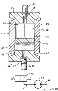
More particularly, and with reference to FIGURE
1, the present invention includes a storage body or
reservoir A which comprises a cylinder body 10 having
top and bottom end plates 12,14 respectively. A bore 15
extends through the top end plate 12 and a suitable
I314238
conventional conduit 18 is secured in the bore so as to
be in fluid communication with the interior of the
cylinder body. A similar bore 20 extends through the
bottom end plate 14 and a suitable conventional conduit
22 is secured in the bore so as to afford communication
with the interior of the cylinder. The cylinder has a
cavity defined by an interior wall 24 which, together
with an inner surface 26 of the top end plate and an
inner surface 28 of the bottom end plate defines a fixed
storage volume 30 in the cylinder. The storage volume
is capable of receiving and storing a ~luid. The size
of the fixed storage volume 30 can, however, be reduced
through the use of the incompressible fluid charge means
C.
With continuing reference to FIGURE 1, a
suitable conventional incompressible fluid storage tank
40 has extending thereinto a fluid line 42 which
communicates the tank 40 with the conduit 22 leading
through the bottom end plate 14. Positioned in the line
42 is a conventional fluid pump 44 as well as a
conventional valve 46 which controls the flow of the
incompressible fluid through the line 42. The pump can
be a uni-directional fixed displacement hydraulic pump
as illustrated or any other suitable conventional type
of hydraulic pump. The valve 46 car. be a three position
valve having a center blocked position as is
illustrated. The valve can be actuated open in either
direction by a solenoid and resiliently biased ~o the
center closed position as illustrated. However, it
should be recogni2ed that any other suitable type of
conventional valve, such as a manually actuated valve,
may be utilized in the fluid line 42 as desired. When
the pump 44 is actuated, a substantially incompressible
fluid such as a lubricant, for example an oil or a
1314238
- 10 -
grease, can be pumped into the cylinder body lO so as to
occupy a portion of the fixed storage volume 3~.
With reference now to FIGURE 3, the circuit
further comprises a compressible fluid reservoir 60
which communicates with a fluid line 62. A suitable
conventional shut-off valve 64 is positioned in the
fluid line 62 adjacent the compressible fluid reservoir
in order to regulate the outflow of compressible fluid
from the reservoir. Also positioned in the fluid line
62 is a first check valve 66 to prevent reverse flow
back into the reservoir 60. Leading from the fluid line
62 is a branch 68 which communicates with the
compressible fluid charge means B. Preferably, the
charge means comprises a suitable piston and cylinder
pumping assembly including a cylinder 70 in which a
piston 72 is adapted to reciprocate and a suitable
conventional actuation means 74 for reciprocating the
piston 72 in the cylinder 70 so as to pressurize the
compressible fluid which flows into the cylinder 70 from
the compressed fluid reservoir once the valve 64 is open.
After the compressible fluid is pressurized, it
can flow further downstream in the fluid line 62 past a
second check valve 80 but it cannot flow back through
the first check valve 66. A suitable conventional fluid
pressure sensor 82 is positioned downstream of the
second check valve 80 to provide a reading of the fluid
pressure in that portion of the fluid line 62. The
continued flow of pressurized fluid through line 62 is
regulated by a shut-off valve 84 which is preferably
air-operator actuated as illustrated. A branch 86 leads
from the fluid line 62, before ~he shut-off valve 84, to
the reservoir A. This branch 86 is in fluid
communication with the conduit 18 that extends through
the top end plate 12 of the storage body or reservoir as
131~238
illustrated in FIGURE 1. In this way, fluid which has
been pressurized by the charge means B to a pressure
higher than that of the fluid in the compressed fluid
reservoir 60 can be stored in the reservoir A.
With reference now again also to FIGURE 1, once
a bottom section of the fixed storage volume 30 of Ihe
reservoir A has been filled with a substantially
incompressible fluid, the compressible fluid can only
flow into a working volume 90 defined in the reservoir.
The working volume is smaller than the fixed storage
volume 30 by an amount depending on the quantity of
incompressible fluid pumped into the storage volume 30.
If desired, a means for separating, at least
substantially, the compressible fluid, i.e. the gas,
from the incompressible fluid, i.e. the lubricant, can
be provided. In one embodiment, a floating piston or
disk 92 can be provided in the cylinder to reduce
turbulence and the mixing of the lubricant with the
gas. The disk 92 can be made of a sin~ered metal or the
like so that it serves not only as a means for
separating but also as a storage means which can absorb
a certain amount of the lubricant. Preferably, the disk
has a loose fit within the cylinder bore such that the
disk has a smaller diameter than the diameter of the
cylinder bore. In this way, a gap exists between a side
periphery of the disk, and a wall of the cylinder bore
to allow the lubricant and the gas to flow ~hrough the
gap and prevent any type of hang-up by the disk in the
cylinder bore.
The cylinder body 10 and the top and bottom end
plates 12,14 can be secured to each other by a suitable
securing means such as weld beads 94 which are
illustrated in FIGURE 1 in order to enable the reservoir
to withstand fairly high pressures. Preferably, the
1314238
71087-lgOD
reservoir can withstand pressures up to approximately 20,000 psi
(137,900 Kpa). The reservoir A can have a storage volume capacity
of approximately 5 to 50 cubic inches (82 to 819 cm3).
~ ith reference now again to Figure 3, the adjustable
working volume compressible fluid reservoir of the present
invention is useful in providing a compressible fluid such as a
gas in a gas injection molding system. In this connection, the
fluid line 62 is in fluid connection with a nozzle means D that
comprises a housing 100 having a core portion 102. The core
portion has a bore 104 extending therethrough. A check valve 106
is provided in a bore 108 in the housing 100. The core portion
bore 104 is in fluid communication with the housing base 108
which, in turn, is in fluid communication with the fluid line 62.
In a first type of use, the valve 46 is opened and the
pump 44 is activated to allow a quantity of a substantially
incompressible fluid e.g., a lubricant, such as oil or grease, to
be pumped from the reservoir 40 into the cylinder body 10. This
pushes the disk 92 upwardly. The quantity of oil or grease which
is allowed to enter the cylinder is only enough to decrease the
working volume 90 of the cylinder to a desired predetermined
volume. This is chosen to be a volume at which the gas, when
compressed to a predetermined initlal pressure, is able to
penetrate the molten plastic injected by a suitable conventional
plastic injection molding machine to form a gas cavity therein.
The volume is also so chosen that the gas is at a predetermined
final pressure when the mold is full and the injection of
thermoplastic matsrial is finished.
If too much grease or oil enters the cylinder A, one
needs merely to energize the valve 46 and utilize
.~
~ 3~23~
- 13 -
the pressure of the gas in the reservoir A in order to
force the lubricant back into the reservoir 40 in any
suitable manner until the correct amount of lubricant is
left in the cylinder. Alternatively, if the pump were
to be a bi-directional type pump, one could energize the
pump in the opposite direction, once the valve were
open, and pump the oil out.
With continuing reference to FIGURE 3, the
valve 64, which may be a pressure reducing valve, is
opened to allow gas to flow from the storage tank 60,
which can be a commercially available tank of nitrogen
gas or the like, through the first check valve 66 and
the second check valve 80 to the storage body or
reservoir A and the compressible fluid charge means B.
The gas which is in the compressible fluid charge means
B is pressurized by pushing the piston 72 upwardly
therein. This pressurizes the gas in the cylinder 70
and urges it back into the fluid line 62 through which
- it flows into the reservoir A through the branch 86
since it cannot flow back through the check valve 66 and
flow in a forw~rd direction through the fluid line 62 is
prevented by the closed valve 84 therein. When the
piston 72 has reached its uppermost position, it trips a
conventional limit switch tnot shown) and the piston is
reversed and ~oves downwardly drawing in another load of
gas to be pressurized. When the piston 72 reaches its
lowermost position, it again trips a limit switch and
the piston is now again caused to move upwardly
compressing the gas in the cylinder 70.
The cycle is repeated until the sensor 82
indicates that the pressure of the gas stored in the
reservoir A is high enough for the particular type of
gas injection molding to be done. Since the working
volume 90 of the reservoir A has been reduced to the
131~23~
- 14 -
correct amount, the correct predeterminsd volume of gas
will thus be stored in the reservoir.
At a given signal, the directional valre 84 is
opened thereby allowing gas to flow through the fluid
line 62 into the housing bore 108 and through the core
portion bore 104 into a mold chamber E. This reduces
the pressure of the gas in the storage chamber A over
time as more and more gas flows out of it until the
pressures in a gas cavity 110 in the thermoplastic
material in the mold chamber E and in the reservoir A
~re equalized.
Another type of use of the reservoir in a gas
injection molding process en~arges the working volume of
the reservoir during the injection molding process. In
this method, a stream of molten plastic material is
introduced at a first approximately constant pressure
into a mold space. A quantity of gas is stored in the
working volume 90 of the reservoir A at a second
pressure which is at least as high as the first
pressure. The gas is then introduced into the stream of
molten plastic material immediately after the molten
material has passed the position at which the gas is
introduced thereby forming a gas cavity in the molten
material. The gas exerts pressure on the surrounding
plastic mat0rial to urge the plastic toward the surfaces
of the mold space. As molten plastic material continues
to be introduced into the mold space, the working volume
of the reservoir A is enlarged while gas continues to be
introduced into the molten material.
With reference now to FIGURE 3, the working
volume 90 of the reservoir A can be increased by
actuating the valve 46 to its return position and by
allowing the pressure of the gas in the working rolume
90 to urge the lubricant out of the reservoir A and back
131~238
- 15 -
into the lubricant reservoir 40. Alternatively with a
bi-directional pump, after the valve is actuated, the
pump can be used to begin pumping the lubricant out of
the reservoir A and back into the lubricant reservoir.
This reduces the gas pressure in the reservoir
at a fairly rapid rate. It has been found that while a
high initial gas pressure is necessary to be~in the
formation of the gas cavity in the molten thermoplastic
material, a considerably lower gas pressure is all that
is necessary to continue the enlargement of such gas
cavity. Additionally, it has been found that such
considerably lower gas pressure is advantageous since
gas at such pressure will not have a tendency to blow
completely through the molten thermoplastic during the
injection molding process. Such a blow through is
highly disadvantageous since it leads to ~he formation
of a defective injection molded produc~ which has to be
scrapped.
Subsequently, the supply of molten material is
terminated when the surfaces of the mold space are
completely covered by the molten maeerial. However, gas
flow from the reservoir to the gas cavity in the mold
space can continue as necessary. The pressure of such
gas is, however, continually reduced, as the plastic
material cools, to a final pressure. The gas fina]
pressure can be lower than the initial pressure at which
the eherlDoplastic material was introduced into the mold
caYity .
In one embodiment, the initial pressure at
which the thermoplastic material is injected into the
mold cavity is approximately 1,500 psi. The pressure at
which the gas is stored in the reservoir is
approximately 2,200 psi. initially. It is at this
pressure that the gas is introduced into the mold cavity
131~238
- 16 -
to begin the formation of a gas cavity therein. As the
size of the reservoir is increased, the gas pressure
decreases until, finally, a final gas pressure of
approximately 500 psi. is reached after the
thermoplastic material has cooled down in the mold
cavity.
Alternatively, it can be seen that if only a
small amount of gas is needed for a particular
application, the compressible fluid pressurizing means B
can itself be utilized as the reservoir of the system.
In this version of the invention, a sui~able volume of
gas is allowed to flow out of the gas storage chamber 60
and into the cylinder 70 of the compressible fluid pump
B at a pressure of approximately 500-1,500 psi (3,448 -
10,343 kPa). Then, the piston 72 in the cylinder
chamber is advanced to pressurize the gas therein to a
pressure of approximately 2,200 psi (15,169 kPa). In
order to prevent the gas from flowing through the branch
86 and into the reservoir A~ a suitable valve (not
illustrated) can be provided in the branch. When thegas in the cylinder 70 has been pressurized to the
required extent, the valve 84 can be opened to allow the
gas to flow through the nozzle means D.
Subsequently, when the pressurized gas has
begun to form the gas cavity 110 in the thermoplastic
material in the mold space, the piston 72 can be
withdrawn in the cylinder 7G to reduce the gas pressure
therein. The molten thermoplastic continues to be fed
into the mold cavity at a pressure of approximately
1,500 psi. (10,343 kPa) at the mold screw (but a
considerably lower pressure at the mold sprue due to the
high Yiscosity of the thermoplastic) while the pressure
at which the gas is fed into the gas cavity formed in
the molten thermoplastic continues to decrease. The
1314238
- 17 -
final pressure in the gas cavity may be on the order of
approximately 500 psi. (3,448 kPa).
With reference now to the alternate embodiment
of PIGURE 2, the invention is there illustrated as
utilizing a second type of reservoir F. For ease of
illustration and appreciation of this alternative, like
components are identified by like numerals with a primed
(') suffix and new components are identified by new
numerals.
In this FIGURE, the reservoir comprises a
cylinder body 10' having top and bottom end plates 120,
122. Each end plate is provided with a dished out
configuration. In other words, the respective inner
surface 124, 126 of each plate is somewhat curved so
lS that the material is thinner at the center of the plate
than around its edges where it meets the cylinder body
10'. It is believed that the provision of curved
surfaces adjacent the outer periphery of each end plate
is advantageous in that the plates will thus be urged by
the fluid pressures inside the storage body storage
volume 30' more tightly against the cylinder body 10' at
the joints thereof to seal such joints against leakage
of either of the fluids out of the storage reservoir F.
As in the embodiment of FIGURE 1, the cylinder
body 10' is secured, such as by weld beads 94' to the
top and bottom end plates 120, 122. Each of the end
plates is also provided with first and second bores 128,
130 which com~unicate with each other and together
extend transversely through the end plate. The first
bore 128 is adapted to threadedly receive a suitable
conventional conduit (not illustrated). The second bore
130 is of a smaller diameter to provide yet more
strength for the end plate while still allowing the
fluid to flow therethrough. The other end plate 122 is
similarly provided with suitable bores.
13~38
- 18 -
A diaphragm 140, made of a resilient material
such as plastic or rubber, can be secured in the
reservoir F if desired. The diaphragm can be provided
with suitable folds 142 to enable the diaphragm to
stretch more easily and accommodate the desired amount
of substantially non-compressible fluid while enlarging
or reducing the size of the working volume 90' of the
reservoir as desired. The diaphragm can be secured by
suitable conventional securing means such as a lip 144
in a groove 146 provided on an inner periphery of the
cylinder body 10'.
With reference now to the alternate embodiment
of FIGURE 47 the invention is there illustrated as
utilizing a second type of compressible fluid charge
means G. For ease of illustration and appreciation of
this alternative, like components are identified by like
numerals with a double primed (") suffix and new
components are identified by new numerals.
In this FIGURE, the compressible fluid charge
means that is positioned in the fluid line 62" is
similarly positioned between a pair of check valves 66"
and 80". The charge means G is a diaphragm pump which
comprises a pump body 160 having therein a diaphragm 162
which is reciprocated in a cavity 164 by a hydraulic
fluid pumped by a piston 166. A desired volume of
hydraulic fluid is urged through a fluid line 168 into a
chamber 170 so that it can be acted on by the piston
166. The piston pushes the hydraulic fluid upwardly out
of the chamber 170 and against a bottom surface of the
diaphragm 162 to urge the diaphragu upwardly in the
cavity 164 of the pump body 160 thereby pressurizing a
gas contained in the cavity above the diaphragm. One
such suitable diaphragm pump is manufactured by Pressure
Products Industries of Warminster, Pennsylvania. The
131~3~
~ 19 -
diaphram pump G can be used in place of the piston type
pump B in order to pressurize the gas to a suitable
pressure so that it can be stored in the reservoir.
One advantage of utilizing the charge means G
of this embodiment would be in a situation where more
than one reservoir needs to be pressurized at the same
time. The diaphragm pump is capable of supplying
pressurized gas for up to four reservoirs
simultaneously, if desired.
Example No. 1
A granular 20% chalk filled polypropylene
plastic was loaded at room temperature into the hopper
of a two stage extruder. The extruder contained a 3 1/2
inch (8.9 cm~) diameter screw with an l:d - 24:1. The
plastic material was plasticated by the extruder screw
running at 30 rpm with 200 psi. (approximately 14 bars)
back pressure.
A part which was to be molded had a varying
wall section from 1.5 mm to 25 mm ~.059 to .984 in) in
thickness and was 46 inches (116.8 cm.) long by 13
inches (33 cm.) wide and 12 (30.5 cm.~ inches high. The
part weight of plastic was to be 2,377 grams ~83.8 oz).
From tho accumulator, resin was shot at a
temperature of 460 F t238 C) into a mold cavity having
the requisite 46" x 13" x 12" volume. The mold was
maintained at 75 F (24 C).
Nitrogen gas injection started after an
injection stroke of .125 inches (.318 cm.). Gas stored
in a cylinder at approximately 2,200 psi. (152 bars) was
introduced through a directional valve to the plastic
being injected. The injection time for the plastic was
7 seconds and at the end of the plastic injection, gas
pressure had decreased to approximately 1,100 psi. (76
13~23g
- 20 -
bars). The gas pressure was held at approximately 75
bars for 60 seconds and was then released to a lower
value of approximately lS to 45 psi. (1 to 3 bars). At
this point, the mold could be opened and the completed
part removed.
The final product had a dimension of 46 x 13 x
lZ inches. The product had a solid integral shell with
a plurality of hollow channels therein in the thicker,
ribbed areas of the product.
Example No. 2
This example is the same as the first with the
exception that after the gas had been initially
introduced to the plastic being injected, and as the gas
continued to be injected the gas storage reservoir's
working volume was expanded thereby reducing the gas
pressure therein. This step also reduced the final
pressure in the molding to approximately 40 bars (580
psi.). The resulting molding was found to be of equal
quality to the higher holding pressure of Example No. 1.
Expansion of the working volume of the gas
storage reservoir was accomplished by storing the gas in
the fluid pump B. With reference now to FIGURE 3, after
decoupling the reservoir A from the fluid line 62, the
gas pressurized in the pump B will remain in the pump
and the line 62 downstream from the check valve 66 until
the valve 84 is opened. Once the valve 84 is opened and
the gas begins to flow out of the cylinder comprising
the pump, the piston 72 thereof is retracted to increase
the working volume of the cylinder thereby rapidly
decreasing the pressure of the gas in the cylinder.
1314 2 3 8 71087-180D
Example No. 3
This example is again the same as the first example
except that the starting or initial gas pressure was reduced from
approximately lS0 bars to 2,200 psi. to approximately 130 bars or
1885 psi. This reduction in initial gas pressure resulted in the
gas not being able to break into the molten plastic mass to create
a gas cavity therein during the plastic injection molding process
The resultant molding therefore has no gas cavity therein and the
mold cavity was therefore not completely filled with the injected
molten plastic. Consequently, the molded part which was produced
has to be scrapped.
Example No. 4
This example is also the same as the first example
except that the initial gas pressure was increased from
approximately 150 bars to 2,200 psi. to approximately 200 bars or
2,900 psi. This increase in initial gas pressure resulted in the
gas breaking completely through the molten plastic mass causing a
blowout of the gas into the mold cavity. The resultant molding
therefore had a gas channel extending therethrough which caused
the mold cavity to be incompletely filled with the molten plastic
The molded part produced consequently had to be scrapped.
From examples 3 and 4j it can be seen that the starting
gas pressure is critical in determining whether a gas cavity is
formed in the molten plastic material and thus whether a usable
molded part is produced. However, the starting gas pressure will
vary with the type of plastic which is injection molded and,
perhaps, with other factors as well.
~31~38
- 22 -
Although the above examples utilized
polypropylene, it should be evident that other types of
plastic ma~erials could also be utilized such as
polyvinylchloride (PVC), polycarbonate, polysulfone,
polystyrene, polyethylene, ABS, and the like as is
desired or required for a particular type of
environment. With each of these plastics, howevçr, a
different set of parameters is necessary for the
pressure and volume of the gas being injected as well as
for the temperature of the plastic being injected.
The subject inYentiOn thus provides a
compressible fluid reservoir having a variable working
volume. Such a variable working volume is necessary
when different predetermined amounts of gas need to be
pressurized to different predeter~ined pressures for gas
pressurized plastic injection molding when utilizing
different types of plastic and when the injection mold
has various different shapes. In this connection,
certain plastics such as polyvinylchloride ~PVC) require
a gas of a predetermined volume at a relatively low
pressure. On the other hand, other types of plastics
such as ABS and the like require gas at a higher
pressure and require different volumes of gas than does
PVC or similar types of plastics. The present invention
provides a reservoir in which a simple, fast, and
relatively friction free change in the working volume
can be accomplished as required instead of having to
resort to providing various sizes of fixed volume
reservoirs.
The invention has been described with reference
to preferred and alternate embodiments. Obviously,
alterations and modifications will occur to others upon
a reading and understanding of this specification. It
is intended to include all such alterations and
modifications insofar as they come within the scope of
the appended claims or the equivalents thereof.