Language selection

Search

Patent 1314303 Summary

Third-party information liability

Some of the information on this Web page has been provided by external sources. The Government of Canada is not responsible for the accuracy, reliability or currency of the information supplied by external sources. Users wishing to rely upon this information should consult directly with the source of the information. Content provided by external sources is not subject to official languages, privacy and accessibility requirements.

Claims and Abstract availability

Any discrepancies in the text and image of the Claims and Abstract are due to differing posting times. Text of the Claims and Abstract are posted:

  • At the time the application is open to public inspection;
  • At the time of issue of the patent (grant).
(12) Patent: (11) CA 1314303
(21) Application Number: 613862
(54) English Title: METHOD FOR SEPARATING GAS AND LIQUID
(54) French Title: METHODE DE SEPARATION GAZ-LIQUIDE
Status: Deemed expired
Bibliographic Data
(52) Canadian Patent Classification (CPC):
  • 302/2
(51) International Patent Classification (IPC):
  • B01D 19/00 (2006.01)
  • B01D 45/02 (2006.01)
  • F17D 1/00 (2006.01)
(72) Inventors :
  • BREKKE, KRISTIAN (Norway)
(73) Owners :
  • AKER ENGINEERING A.S (Norway)
(71) Applicants :
(74) Agent: G. RONALD BELL & ASSOCIATES
(74) Associate agent:
(45) Issued: 1993-03-09
(22) Filed Date: 1989-09-28
Availability of licence: N/A
(25) Language of filing: English

Patent Cooperation Treaty (PCT): No

(30) Application Priority Data:
Application No. Country/Territory Date
88.5302 Norway 1988-11-28
89.1194 Norway 1989-03-17

Abstracts

English Abstract


- 6 -

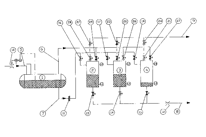
ABSTRACT: A method for the transportation and separation of
gas from liquid and solid media in one or several
stages in a manner so that the pressure in the
gaseous phase from an early separator stage or
from another gas deposit is utilized for the
transportation of the fluids produced in sub-
sequent separator stages. Gas which is separated
off at high pressure in an early separator stage
or gas from another gas deposit is led into a se-
parator which has carried out separation at a
lower pressure. The high pressure gas forces out
the ready separated fluid which is present in the
separator receiving the high pressure gas. The
separator stage which receives high pressure gas
from a preceding stage or another gas source, is
made up of several identical separators which al-
ternate in carrying out the functional phases
stated below in the sequence indicated so that
there is at all times one separator carrying out
functions within one phase.

Phase 1 Gas is separated from liquid at a pres-
sure necessary to maintain export of gas
from the process.

Phase 2 Liquid is exported out of the separator
by means of gas from a preceding separa-
tor stage or from another gas deposit.

Phase 3 The separator is decompressed by gas be-
ing let out of the separator to a gas
export line.


Claims

Note: Claims are shown in the official language in which they were submitted.


THE EMBODIMENTS OF THE INVENTION IN WHICH AN EXCLUSIVE
PROPERTY OR PRIVILEGE IS CLAIMED ARE DEFINED AS FOLLOWS:

1. A process for the transportation of gas and
liquid or solid media and the separation of gas from liquid
or solid media in a manner so that the pressure in the gas
separated off in one separator stage is used for the
transportation of separated fluids from a subsequent separator
stage, comprises the steps of:
(a) separating gas off at high pressure in one
separator stage or adding it from another gas source;
(b) directing said separated or added gas into a
separator containing fluid from which gas has been separated
at a lower pressure; and
(c) said higher pressure gas forcing out already
separated fluid present in the separator receiving said high
pressure gas.

2. A process as claimed in claim 1, wherein the
lower pressure separator comprises a plurality of
substantially identical separators, each of said separators
operating in a work cycle and alternating in carrying out in
the sequence indicated, the function phases of said process,
said process being such as to ensure that one separator
carries out is functions within one phase.

3. A process as claimed in claim 1 or 2, wherein
(a) phase 1 of the process is the separation of gas
from liquid at a pressure necessary to maintain export of gas
from the process;
(b) phase 2 is the output of liquid from the
separator to an output line by gas from a preceding separator
stage or from another gas deposit being fed into the
separator; and
(c) phase 3 is decompressing the separator be
directing gas from it to a gas output line.


4. A process as claimed in claim 1, wherein
separators in the separator stage which receives said higher
pressure gas are decompressed at constant mass flow of gas
through a decompression valve to a gas output line after
completion of the phase for transportation of oil, the
separators being decompressed sequentially.

5. A system for the separation and transportation
of gas and liquid, comprising first separator means for the
separation of gas from the liquid at a first pressure, and
second separator means for operation at a lower pressure than
said first pressure and for separation of further gas from the
liquid to be separated out in said first separator means said
second separator means including at least one separator vessel
the upper part of said vessel being connected to said first
separator means through gas and liquid supply lines and being
further connected to a gas transportation line the lower part
of said vessel being connected to a liquid transportation
line.

6. A system according to claim 5, wherein said
second separator means includes at least three separator
vessels connected in parallel.


Description

Note: Descriptions are shown in the official language in which they were submitted.


1 31 ~303


This invention relates generally to a process and
separator system for the separation of gas from liquid and
solid media and the conveyance of the gas and liquid without
the addition of energy to the separation process utilized.
5An object of the invention is to be able to retain
a substantial portion of the conveyance energy or
transportation pressure throughout the separating process.
The accompanying drawing schematically illustrates
an embodiment of the invention.
10According to the present invention a process for the
transportation of gas and liquid or solid media and the
separation of gas from liquid or solid media in a manner so
that the pxessure in the gas separated off in one separator
stage is usPd for the transportation of separated fluids from
a subsequent separator stage, comprising the steps of
separating gas off at high pressure in one separator stage or
adding it from another gas source and directing said separated
or added gas into a separator containing fluid from which gas
; has been separated at a lower pressure, said higher pressure
gas forcing out already separated fluid present in the
separator receiving said high pressure gas.
The example of the present invention described
herein is a two-stage process, in which the oil and gas are
the separated phases and in which no water is separated off
and in which there is only one line for removing gas from the
process and one line for removing oil.
The separator transportation system of the present
invention may be situated, for example, immediately downstream
of an oil/gas well or a transportation line.
3~The process carried out with the separator
transportation system has at least one separation stage. If
the process includes two or more separation stages, then in
the first stage, the contents of high pressure separator 1
will be in a steady state of separation of gas and water, if
- 35 any, from the oil at a high pressure (approximately equal to
the starting pressure in the transport line 8 mentioned
~'~
" A;~ ..

: .

1 31 /~303
.

hereinafter for stabilized oil). Any water separated off may
`~ be fed out of the high pressure separator 1 together with any
sand produced via a water transportation line. Any gas from
the high pressure separator 1 is fed to separators of a second
stage 2, 3, 4 for the purpose of forcing the already
stabilized oil from separators of the second stage 2, 3, 4
into the oil transportation line 8.
Separation in the second stage, hereinafter referred
to as the low pressure separator cycle, is effected by several
identical separators 2, 3, 4 which work in three phases. The
separators 2, 3, 4 alternate in carrying out the three phases
so that there is at all times one separator carrying out one
of the phases.
Phase 1 (SeparationL
Gas is separated from oil at the same time as gas
~ is removed at a pressure (necessary transportation pressure
`~ for exported gas) lower than that in the preceding separator.
For separator 2 to separate gas from oil`, the oil inlet valve
16 of the separator is open, its gas inlet valve 25 is closed,
its oil output valve 13 is closed, and its ~as outlet valve
l9 is open. A compression unit may optionally be installed
ahead of the export facilities for the separated gas.
Phase 2 (Trans~ortation)
Oil is transported at a high pressure which is in
part determined by the necessary transportation pressure for
~- exported oil. For separator 3 to remove oil, the oil inlet
valve 17 of the separator is closed, its gas inlet valve 26
is open, its oil outlet valve 14 is open, and its gas outlet
valve 20 is closed. Mechanical devices may optionally be
installed to reduce the contact surface area of gas and oil.
Pkase 3 (Decompression)
The separator 4 is decompressed by exhausting gas
at a constant mass flow through the decompression valve 24,
either to a dedicated gas transportation line or to the same
transportation line 9 as is used for gas separated o~f in
Phase 1. For a separator in the low pressura separator
.


.,

:,'

1314303
cycle to decompress gas to the gas expart line, its oil
inlet valve 18, gas inlet valve 27 and oil outlet valve 15
are closed, while its gas outlet valve 21 and decompression
valve 24 are Gpen.
The number of separators in the low pressure
separator cycle is determined by the ratio between the
times spent by the separators 2, 3, 4 in carrying out the
three different phases. This example is based on three
being the necessary number of separators.
One of the separators 2, 3, 4 in the low pressure
separator cycle outputs oil at any given time, while
another is in the process of decompressing and a third one
is separating.
A11 separators 2, 3, 4 of the low pressure
separator cycle are connected to the oil supply line 7 and
the gas supply line 6 from high pressure separator l or
possibly direct from oil or gas wells if the first stage or
high pressure separator 1 is waived.
The separators 2, 3, 4 of the low pressure
separator cycle are connected to output lines 8, 9 both for
oil and gas. All these lines are fitted with shut-off
valYes which are controlled, for example by a computer, on
the basis of the levels of liquid in the low pressure
separator cycle, as well as mass and balance of energy in
the separator process. For the control of pressure and
rates of flow, adjustment valves 10, 11 are fitted to the
oil output line 8, the inlet for oil to the low pressure
separator cycle, and any inlet for oil to the high pressure
separator.
The txansportation pressure which it is possible
to maintain at the same time as the desired flow volume is
maintained for output oil, is mainly determined by the
composition of the liquid and gas being separated. The
larger the proportion of light components ~gas componentS),
the higher is the pressure which it is possible ~o maintain
for output of oil.


1 A,

Representative Drawing
A single figure which represents the drawing illustrating the invention.
Administrative Status

For a clearer understanding of the status of the application/patent presented on this page, the site Disclaimer , as well as the definitions for Patent , Administrative Status , Maintenance Fee  and Payment History  should be consulted.

Administrative Status

Title Date
Forecasted Issue Date 1993-03-09
(22) Filed 1989-09-28
(45) Issued 1993-03-09
Deemed Expired 2003-03-10

Abandonment History

There is no abandonment history.

Payment History

Fee Type Anniversary Year Due Date Amount Paid Paid Date
Application Fee $0.00 1989-09-28
Registration of a document - section 124 $0.00 1992-12-31
Maintenance Fee - Patent - Old Act 2 1995-03-09 $100.00 1995-03-08
Maintenance Fee - Patent - Old Act 3 1996-03-11 $100.00 1996-02-29
Maintenance Fee - Patent - Old Act 4 1997-03-10 $100.00 1997-02-26
Maintenance Fee - Patent - Old Act 5 1998-03-09 $150.00 1998-02-23
Maintenance Fee - Patent - Old Act 6 1999-03-09 $150.00 1999-02-24
Maintenance Fee - Patent - Old Act 7 2000-03-09 $150.00 2000-02-24
Maintenance Fee - Patent - Old Act 8 2001-03-09 $150.00 2001-02-27
Owners on Record

Note: Records showing the ownership history in alphabetical order.

Current Owners on Record
AKER ENGINEERING A.S
Past Owners on Record
BREKKE, KRISTIAN
Past Owners that do not appear in the "Owners on Record" listing will appear in other documentation within the application.
Documents

To view selected files, please enter reCAPTCHA code :


To view images, click a link in the Document Description column. To download the documents, select one or more checkboxes in the first column and then click the "Download Selected in PDF format (Zip Archive)" or the "Download Selected as Single PDF" button.

List of published and non-published patent-specific documents on the CPD .

If you have any difficulty accessing content, you can call the Client Service Centre at 1-866-997-1936 or send them an e-mail at CIPO Client Service Centre.


Document
Description 
Date
(yyyy-mm-dd) 
Number of pages   Size of Image (KB) 
Drawings 1993-11-10 1 32
Claims 1993-11-10 2 78
Abstract 1993-11-10 1 35
Cover Page 1993-11-10 1 17
Description 1993-11-10 3 164
Representative Drawing 2000-08-01 1 24
Fees 2000-02-24 1 47
Fees 1999-02-24 1 49
Fees 2001-02-27 1 45
Fees 1998-02-23 1 50
PCT Correspondence 1992-11-18 1 27
Prosecution Correspondence 1992-03-12 2 73
Prosecution Correspondence 1990-07-19 1 39
Prosecution Correspondence 1990-05-07 2 65
Examiner Requisition 1991-12-19 1 53
Fees 1997-02-26 1 43
Fees 1996-02-29 1 41
Fees 1995-03-08 1 42