Sélection de la langue

Search

Sommaire du brevet 1314303 

Énoncé de désistement de responsabilité concernant l'information provenant de tiers

Une partie des informations de ce site Web a été fournie par des sources externes. Le gouvernement du Canada n'assume aucune responsabilité concernant la précision, l'actualité ou la fiabilité des informations fournies par les sources externes. Les utilisateurs qui désirent employer cette information devraient consulter directement la source des informations. Le contenu fourni par les sources externes n'est pas assujetti aux exigences sur les langues officielles, la protection des renseignements personnels et l'accessibilité.

Disponibilité de l'Abrégé et des Revendications

L'apparition de différences dans le texte et l'image des Revendications et de l'Abrégé dépend du moment auquel le document est publié. Les textes des Revendications et de l'Abrégé sont affichés :

  • lorsque la demande peut être examinée par le public;
  • lorsque le brevet est émis (délivrance).
(12) Brevet: (11) CA 1314303
(21) Numéro de la demande: 1314303
(54) Titre français: METHODE DE SEPARATION GAZ-LIQUIDE
(54) Titre anglais: METHOD FOR SEPARATING GAS AND LIQUID
Statut: Périmé et au-delà du délai pour l’annulation
Données bibliographiques
(51) Classification internationale des brevets (CIB):
  • B01D 19/00 (2006.01)
  • B01D 45/02 (2006.01)
  • F17D 1/00 (2006.01)
(72) Inventeurs :
  • BREKKE, KRISTIAN (Norvège)
(73) Titulaires :
  • AKER ENGINEERING A.S
(71) Demandeurs :
  • AKER ENGINEERING A.S (Norvège)
(74) Agent: G. RONALD BELL & ASSOCIATES
(74) Co-agent:
(45) Délivré: 1993-03-09
(22) Date de dépôt: 1989-09-28
Licence disponible: S.O.
Cédé au domaine public: S.O.
(25) Langue des documents déposés: Anglais

Traité de coopération en matière de brevets (PCT): Non

(30) Données de priorité de la demande:
Numéro de la demande Pays / territoire Date
88.5302 (Norvège) 1988-11-28
89.1194 (Norvège) 1989-03-17

Abrégés

Abrégé anglais


- 6 -
ABSTRACT: A method for the transportation and separation of
gas from liquid and solid media in one or several
stages in a manner so that the pressure in the
gaseous phase from an early separator stage or
from another gas deposit is utilized for the
transportation of the fluids produced in sub-
sequent separator stages. Gas which is separated
off at high pressure in an early separator stage
or gas from another gas deposit is led into a se-
parator which has carried out separation at a
lower pressure. The high pressure gas forces out
the ready separated fluid which is present in the
separator receiving the high pressure gas. The
separator stage which receives high pressure gas
from a preceding stage or another gas source, is
made up of several identical separators which al-
ternate in carrying out the functional phases
stated below in the sequence indicated so that
there is at all times one separator carrying out
functions within one phase.
Phase 1 Gas is separated from liquid at a pres-
sure necessary to maintain export of gas
from the process.
Phase 2 Liquid is exported out of the separator
by means of gas from a preceding separa-
tor stage or from another gas deposit.
Phase 3 The separator is decompressed by gas be-
ing let out of the separator to a gas
export line.

Revendications

Note : Les revendications sont présentées dans la langue officielle dans laquelle elles ont été soumises.


THE EMBODIMENTS OF THE INVENTION IN WHICH AN EXCLUSIVE
PROPERTY OR PRIVILEGE IS CLAIMED ARE DEFINED AS FOLLOWS:
1. A process for the transportation of gas and
liquid or solid media and the separation of gas from liquid
or solid media in a manner so that the pressure in the gas
separated off in one separator stage is used for the
transportation of separated fluids from a subsequent separator
stage, comprises the steps of:
(a) separating gas off at high pressure in one
separator stage or adding it from another gas source;
(b) directing said separated or added gas into a
separator containing fluid from which gas has been separated
at a lower pressure; and
(c) said higher pressure gas forcing out already
separated fluid present in the separator receiving said high
pressure gas.
2. A process as claimed in claim 1, wherein the
lower pressure separator comprises a plurality of
substantially identical separators, each of said separators
operating in a work cycle and alternating in carrying out in
the sequence indicated, the function phases of said process,
said process being such as to ensure that one separator
carries out is functions within one phase.
3. A process as claimed in claim 1 or 2, wherein
(a) phase 1 of the process is the separation of gas
from liquid at a pressure necessary to maintain export of gas
from the process;
(b) phase 2 is the output of liquid from the
separator to an output line by gas from a preceding separator
stage or from another gas deposit being fed into the
separator; and
(c) phase 3 is decompressing the separator be
directing gas from it to a gas output line.

4. A process as claimed in claim 1, wherein
separators in the separator stage which receives said higher
pressure gas are decompressed at constant mass flow of gas
through a decompression valve to a gas output line after
completion of the phase for transportation of oil, the
separators being decompressed sequentially.
5. A system for the separation and transportation
of gas and liquid, comprising first separator means for the
separation of gas from the liquid at a first pressure, and
second separator means for operation at a lower pressure than
said first pressure and for separation of further gas from the
liquid to be separated out in said first separator means said
second separator means including at least one separator vessel
the upper part of said vessel being connected to said first
separator means through gas and liquid supply lines and being
further connected to a gas transportation line the lower part
of said vessel being connected to a liquid transportation
line.
6. A system according to claim 5, wherein said
second separator means includes at least three separator
vessels connected in parallel.

Description

Note : Les descriptions sont présentées dans la langue officielle dans laquelle elles ont été soumises.

1 31 ~303
This invention relates generally to a process and
separator system for the separation of gas from liquid and
solid media and the conveyance of the gas and liquid without
the addition of energy to the separation process utilized.
5An object of the invention is to be able to retain
a substantial portion of the conveyance energy or
transportation pressure throughout the separating process.
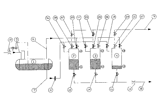
The accompanying drawing schematically illustrates
an embodiment of the invention.
10According to the present invention a process for the
transportation of gas and liquid or solid media and the
separation of gas from liquid or solid media in a manner so
that the pxessure in the gas separated off in one separator
stage is usPd for the transportation of separated fluids from
a subsequent separator stage, comprising the steps of
separating gas off at high pressure in one separator stage or
adding it from another gas source and directing said separated
or added gas into a separator containing fluid from which gas
; has been separated at a lower pressure, said higher pressure
gas forcing out already separated fluid present in the
separator receiving said high pressure gas.
The example of the present invention described
herein is a two-stage process, in which the oil and gas are
the separated phases and in which no water is separated off
and in which there is only one line for removing gas from the
process and one line for removing oil.
The separator transportation system of the present
invention may be situated, for example, immediately downstream
of an oil/gas well or a transportation line.
3~The process carried out with the separator
transportation system has at least one separation stage. If
the process includes two or more separation stages, then in
the first stage, the contents of high pressure separator 1
will be in a steady state of separation of gas and water, if
- 35 any, from the oil at a high pressure (approximately equal to
the starting pressure in the transport line 8 mentioned
~'~
" A;~ ..
: .

1 31 /~303
.
hereinafter for stabilized oil). Any water separated off may
`~ be fed out of the high pressure separator 1 together with any
sand produced via a water transportation line. Any gas from
the high pressure separator 1 is fed to separators of a second
stage 2, 3, 4 for the purpose of forcing the already
stabilized oil from separators of the second stage 2, 3, 4
into the oil transportation line 8.
Separation in the second stage, hereinafter referred
to as the low pressure separator cycle, is effected by several
identical separators 2, 3, 4 which work in three phases. The
separators 2, 3, 4 alternate in carrying out the three phases
so that there is at all times one separator carrying out one
of the phases.
Phase 1 (SeparationL
Gas is separated from oil at the same time as gas
~ is removed at a pressure (necessary transportation pressure
`~ for exported gas) lower than that in the preceding separator.
For separator 2 to separate gas from oil`, the oil inlet valve
16 of the separator is open, its gas inlet valve 25 is closed,
its oil output valve 13 is closed, and its ~as outlet valve
l9 is open. A compression unit may optionally be installed
ahead of the export facilities for the separated gas.
Phase 2 (Trans~ortation)
Oil is transported at a high pressure which is in
part determined by the necessary transportation pressure for
~- exported oil. For separator 3 to remove oil, the oil inlet
valve 17 of the separator is closed, its gas inlet valve 26
is open, its oil outlet valve 14 is open, and its gas outlet
valve 20 is closed. Mechanical devices may optionally be
installed to reduce the contact surface area of gas and oil.
Pkase 3 (Decompression)
The separator 4 is decompressed by exhausting gas
at a constant mass flow through the decompression valve 24,
either to a dedicated gas transportation line or to the same
transportation line 9 as is used for gas separated o~f in
Phase 1. For a separator in the low pressura separator
.
.,
:,'

1314303
cycle to decompress gas to the gas expart line, its oil
inlet valve 18, gas inlet valve 27 and oil outlet valve 15
are closed, while its gas outlet valve 21 and decompression
valve 24 are Gpen.
The number of separators in the low pressure
separator cycle is determined by the ratio between the
times spent by the separators 2, 3, 4 in carrying out the
three different phases. This example is based on three
being the necessary number of separators.
One of the separators 2, 3, 4 in the low pressure
separator cycle outputs oil at any given time, while
another is in the process of decompressing and a third one
is separating.
A11 separators 2, 3, 4 of the low pressure
separator cycle are connected to the oil supply line 7 and
the gas supply line 6 from high pressure separator l or
possibly direct from oil or gas wells if the first stage or
high pressure separator 1 is waived.
The separators 2, 3, 4 of the low pressure
separator cycle are connected to output lines 8, 9 both for
oil and gas. All these lines are fitted with shut-off
valYes which are controlled, for example by a computer, on
the basis of the levels of liquid in the low pressure
separator cycle, as well as mass and balance of energy in
the separator process. For the control of pressure and
rates of flow, adjustment valves 10, 11 are fitted to the
oil output line 8, the inlet for oil to the low pressure
separator cycle, and any inlet for oil to the high pressure
separator.
The txansportation pressure which it is possible
to maintain at the same time as the desired flow volume is
maintained for output oil, is mainly determined by the
composition of the liquid and gas being separated. The
larger the proportion of light components ~gas componentS),
the higher is the pressure which it is possible ~o maintain
for output of oil.
1 A,

Dessin représentatif
Une figure unique qui représente un dessin illustrant l'invention.
États administratifs

2024-08-01 : Dans le cadre de la transition vers les Brevets de nouvelle génération (BNG), la base de données sur les brevets canadiens (BDBC) contient désormais un Historique d'événement plus détaillé, qui reproduit le Journal des événements de notre nouvelle solution interne.

Veuillez noter que les événements débutant par « Inactive : » se réfèrent à des événements qui ne sont plus utilisés dans notre nouvelle solution interne.

Pour une meilleure compréhension de l'état de la demande ou brevet qui figure sur cette page, la rubrique Mise en garde , et les descriptions de Brevet , Historique d'événement , Taxes périodiques et Historique des paiements devraient être consultées.

Historique d'événement

Description Date
Inactive : CIB de MCD 2006-03-11
Le délai pour l'annulation est expiré 2003-03-10
Lettre envoyée 2002-03-11
Accordé par délivrance 1993-03-09

Historique d'abandonnement

Il n'y a pas d'historique d'abandonnement

Historique des taxes

Type de taxes Anniversaire Échéance Date payée
TM (catégorie 1, 5e anniv.) - générale 1998-03-09 1998-02-23
TM (catégorie 1, 6e anniv.) - générale 1999-03-09 1999-02-24
TM (catégorie 1, 7e anniv.) - générale 2000-03-09 2000-02-24
TM (catégorie 1, 8e anniv.) - générale 2001-03-09 2001-02-27
Titulaires au dossier

Les titulaires actuels et antérieures au dossier sont affichés en ordre alphabétique.

Titulaires actuels au dossier
AKER ENGINEERING A.S
Titulaires antérieures au dossier
KRISTIAN BREKKE
Les propriétaires antérieurs qui ne figurent pas dans la liste des « Propriétaires au dossier » apparaîtront dans d'autres documents au dossier.
Documents

Pour visionner les fichiers sélectionnés, entrer le code reCAPTCHA :


Pour visualiser une image, cliquer sur un lien dans la colonne description du document. Pour télécharger l'image (les images), cliquer l'une ou plusieurs cases à cocher dans la première colonne et ensuite cliquer sur le bouton "Télécharger sélection en format PDF (archive Zip)" ou le bouton "Télécharger sélection (en un fichier PDF fusionné)".

Liste des documents de brevet publiés et non publiés sur la BDBC .

Si vous avez des difficultés à accéder au contenu, veuillez communiquer avec le Centre de services à la clientèle au 1-866-997-1936, ou envoyer un courriel au Centre de service à la clientèle de l'OPIC.


Description du
Document 
Date
(aaaa-mm-jj) 
Nombre de pages   Taille de l'image (Ko) 
Page couverture 1993-11-10 1 15
Abrégé 1993-11-10 1 31
Revendications 1993-11-10 2 69
Dessins 1993-11-10 1 28
Description 1993-11-10 3 144
Dessin représentatif 2000-08-01 1 24
Avis concernant la taxe de maintien 2002-04-08 1 179
Correspondance reliée au PCT 1992-11-18 1 27
Correspondance de la poursuite 1992-03-12 2 73
Correspondance de la poursuite 1990-07-19 1 39
Correspondance de la poursuite 1990-05-07 2 65
Demande de l'examinateur 1991-12-19 1 53
Taxes 1999-02-24 1 49
Taxes 2001-02-27 1 45
Taxes 1998-02-23 1 50
Taxes 2000-02-24 1 47
Taxes 1997-02-26 1 43
Taxes 1996-02-29 1 41
Taxes 1995-03-08 1 42