Note: Descriptions are shown in the official language in which they were submitted.
1 3 1 45~
C~BLE SUPPORT ~SSEMBLY AND ME~I~OD OF
STRINGING WIT~ S~ME
Backqround of the Invention
This invention pertains to the art of cable support
structures and more particularly to a cable support
assembly for a fiber optic cable and method of stringing
same.
The invention is particularly applicable to an all
dielectric cable support assembly and wlll be described
with reference thereto. ~owever, it will be appreciated
that the invention has broader applications and may be
advantageously employed in supporting and stringing other
cables with equal success.
The proven performance of optical fibers has
resulted in an increasing use of fiber optic cables for
data transmission. Fiber optic cables, though, require
special handling as a result of the fragile optical fibers
contained therein. Additionally, beyond the mere
mechanical gripping problems that must be overcome, it is
necessary to protect the fiber~optic cable against
electrical degradation created by strong electrical fields
of nearby energized cables.
Suspension from poles or other support structures
subjects cables to both dynamic and static stresses. The
weight of the cable being suspended at only selected points
along its longitudinal extent is the principal component of
the static stress. I'he dynamic stress primarily arises
from oscillation of the fiber optic cable. For example,
aeolian vibration is a natural response resulting from wind
vortices passing over the suspended cable. Oscillation of
the cable can lead to fatigue damage as a result of
repeated flexural bending. Some latitude must be provided
by the support structure to permit limited oscillation of
t 3 1 ~
the cable without the adverse effect of flexural fa~igue.
Other support devices do not adequately accommodate
the stringing, initial, or final sag of the cable.
Although a cable extends axially through the support
member, it is necessary to incorporate a predetermined sag
of the cable from one pole to the next pole. The amount of
sag, and likewise the sag angle, will changQ with different
temperatures and field conditions, such as the terrain and
spacing between poles.
Ideally, a cable will extend in a straight line
whenever possible to minimize load factors on the support
members. Unfortunately, the cable must curve or deviate
from its longitudinal extent. If the deviation from a
straight line is not factored into the support member
structure, abrasion of the fiber optic cable can result.
Again, prior art devices have not adequately accommodated
for less than ideal conditions encountered in the field.
Still another difficulty encountered with prior art
support devices results from temporarily stringing the
cable before final suspension adjustments are made.
Typically, temporary supports are used for the initial
stringing of the cable. Thereafter, separate, permanent
support members are mounted to an associated structure such
as a pole to receive the cable. The temporary supports may
then be removed once the permanent support members are in
place.
This method necessarily requires that at least an
extra step be undertaken in order to suspend the cables.
That is, the temporary support must also be secured to the
pole and then removed once the permanent support members
are in place. This involves a waste of time, labor, and
material all at an increased cost to the consumer.
The subject invention is deemed to provide a
reliable support structure particularly adapted for fiber
optic cables and overcome the above-noted shortcomings of
1 31 1lt5')~',
the prior art.
Summary of the Invention
The present invention contemplates a new and
improved apparatus for supporting cables from an associated
structure, as well as an associated method of stringing
cable through use of same.
~ ccording to the present invention, there is
provided a cable support assembly having a two-part body
formed of a dielectric material. Elongated recesses are
defined in each body member to form an aperture through the
body when the body members are placed in mating engagement.
The body members are locked against relative axial movement
and means for selectively securing the body members
together is provided. A dielectric cushion member is also
formed of two mating portions and received in the recesses
of the first and second body members, respectively.
According to another aspect of the invention, means
for limiting relative axial movement between the cushion
member and body is provided.
According to yet another aspect of the invention, an
enlarged boss is formed entirel~y on one body member for
securing tlle support assembly to an associated structure.
~ ccording to still another aspect of the invention,
generally frusto-conical tapered regions are provided at
opposite ends of the body aperture.
In accordance with a method of stringing cable with
the subject apparatus, a first body member is mounted to
the associated support structure, a spacer inserted between
the first and second body membexs, and the second body
member secured in spaced relation to a first body member.
A cable is then fed between the first and second body
members and the spacer removed from therebetween. Prior to
final mating engagement of the body members, a cushion
member is positioned between the first and second body
1 3 1 '.5
members around the cable.
A principal advantage of the invention resides in
the unique mechanical performance characteristics of the
support assembly.
Yet another advantage of the invention is found i~
the ability to guard against electrical degradation of the
fiber optic cable received therein.
Still another advantage of the invention is found in
the protection against destructive bending during
unbalanced loading on the cable.
A still further advantage resides in the method of
stringing the cable.
Still other advantages and benefits of the invention
will become apparent to those skilled in the art upon a
reading and understanding of the following detailed
description.
Brief DescriDtion of the Drawin~s
The invention may take physical form in certain
parts and arrangements of parts, a preferred embodiment and
method of which will be described in detail in this
specification and'illustrated in the accompanying drawings
which form a part hereof, and wherein:
FIGURE 1 is an exploded perspective view of the
support assembly receiving a fiber optic cable shown in
phantom therethrough;
FIGURE 2A is a plan view of an interior face of a
first body member;
FIGURE 2B is a plan view of the interior face of a
second body member adapted for mating engagement with the
first body member;
FIGURE 3A is an end view of the first body member;
FIGURE 3B is an end view of the second body member
FIGURE 4A is a bottom view of the first body member;
FI GURE 4 B is a bottom view of the second body
1 3 1 4- '-) , 3
member;
FIGU~E 5 is a plan view of a cushion member portion
partially shown in cross-section;
FIGURE 6 is a top view of the cushion member
portion; and,
FIGU~E 7 is an end view of the cushion member
portion according to the subject invention.
Detailed DescriDtion of the Preferred Embodiment and Method
Referring now to the drawings wherein the showings
are for purposes of illustrating the preferred embodiment
and method of the invention only and not for purposes of
limiting same, the FIGU~ES show a cable support assembly A
receiving a cable such as fiber optic cable B therethrough.
The structural arrangement of the fiber optic cable may
ta~e various configurations, none of which form a part of
the subject invention. ~urther discussion of the structure
and function of conventional fiber optic cables is,
therefore, deemed unnecessary to a full and complete
understanding of the subject invention.
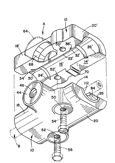
The cable support assembly includes a two-part body
defined by first and second body members 10, 12. The body
members are preferably formed of a substantially rigid
urethane material. The urethane material is preferred
because of its high strength and dielectrical properties.
It is also contemplated that certain situations may require
even higher strength properties. Incorporation of carbon
or glass fibers, or similar strengthening materials, may be
used to meet increased strength properties. Of course, it
will be understood that still other comparable dielectric
or composite dielectric materials exhibiting similar
structural and functional characteristics may be used with
equal success.
Referring now to FIGU~ES 2A, 3A, and 4A, the
particulars of the first body member 10 will be described
1 3 1 ~ 5
in greater detail. A generally planar interior face 14
includes an elongated, generally arcuate recess 16
extending axially from a first end 18 to a second end 20.
The recess 16 preferably has a smooth face for reasons that
will become more apparent below. The recess has an
intermediate, central portion 22 of generally constant
dimension and tapering regions 24, 26 increasing in
diameter as the recess extends toward the respective first
and second ends 18, 20. A first inset groove 30 is
interposed between the central portion 22 and first
tapering region 24. Likewise, a second inset groove 32 is
interposed between the central portion and second tapering
region 26. The grooves flare radially outward, i.e.
increase in depth, as they extend axially toward their
respective first and second ends. An abrupt reduction in
diameter defines a shoulder 34, 36 at the merger area of
the grooves 30, 32 with the respective first and second
tapering regions 24, 26.
A first securing means defined by an enlarged boss
44 is centrally disposed along the axial length of the
first body member. The boss is generally cylindrical in
conformation and includes an internally threaded aperture
46 adapted to receive a conventional fastener (not shown)
for securing the first body member to an associated
structure. The boss is entirely defined in the first body
member with a central axis of the aperture 46 generally
aligned with the planar interior face 14.
Approximately half of the boss, therefore, extends
outwardly from the first body member in a generally
cantilevered arrangement. ~n inwardly extending cutout or
notch 48 is also defined in the central portion of the
first body member but on an opposite side of the recess 16
from the boss. In the preferred arrangement, the notch has
a cubical conformation although other notch configurations
may be used without departing ~rom the ~cope and intent of
- 1 3 1 ~1- 5 lj
the subject invention. The function and purpose of the
notch will be described further hereinbelow.
First and second apertures 50, 52 extend generally
perpendicular to the interior face 14 and extend entirely
through the first body member. The apertures are adapted
to receive selected fasteners such as bolts 54, 56,
respectively. In the embodiment shown, the fasteners are
selectively inserted into the apertures for securing the
first and second body members together. Alternatively,
though, the fastellers may be molded into either the first
or second body members to facilitate assembly of the body.
The first and second apertures have a predetermined
positional arrangement in the body members. Specif;cally,
the apertures 50, 52 are placed on opposite sides of the
recess 16. This provides a balanced arrangement relative
to a longitudinal axis of the body. Additionally, the
apertures are positioned on opposite sides of the central
axis of aperture 46.
The second body member 12 is particularly
illustrated in FIGURES 2B, 3B and 4B. Since the second
body member is suhstantially identical to that of the first
body member, and for ease of illustration and
understanding, like elements are identified by like
numerals with a primed (') suffix and new elements are
identified by new numerals. The second body member
includes a generally planar interior face 14' and an
elongated arcuate recess 16'. First and second radially
outward tapering regions 24', 26' are defined at the
respective first and second ends 18l~ 20' of the second
body member. Interposed between the tapering regions is a
generally constant diameter central portion 22' d~fined
along a major portion of the axial length of the recess.
Interposed between each tapering region and the
central portion are defined first and second grooves 30',
32'. The grooves spread axially and radially outwardly to
r ~
define a generally rr~ to-conical configuration. In fact,
the grooves diverge more s~larply th~n the tapering regions
24, 2G to define respective shoulders 34', 36' therewith.
~ thin-walled sleeve 64 (FIGURE 1) has a generally
inllcr semi-cylindrical configuration adapted for ~ating
cngagement with the semi-cylindrical external surface of
t~le boss 4~ of tlle f;L-st body member. The thin-walled
sleeve provides minor support for the boss area of the
first body member wh~rl the hody ~nembers are placed in
mating engagement. lts primary functlon~ though, is to
facilitate alignment and orientation of the first and
second body members in the field. In fact, it is
contemplated that other cable support embodiments may be
used without incorporating a thin-walled sleeve (FIGURES
2B, 3B, and 4B). On the other hand, a recessed well 68 is
disposed between the sleeve and recess 16'. The well also
accommodates the enlarged boss 44 of the first body member
and is required to join the body members in mating
engagement.
An outwardly extending tab 70 is disposed on the
other side of the recess 16' from the well 68~ The
sidewalls of the tab are configured for mating receipt in
the notch 48. The tab and notch cooperate to prevent or
lock the first and second body members against relative
axial movement when the body members are matingly secured
together. As descri.bed above, still other conformations of
the tab and notch may be used without departing from the
scope and intent of the arrangement. First and second
apertures 50', 52' define continuations of apertures 50, 52
of the first body member. The apertures 50', 52' extend
generally perpendicularly to the longitudinal axis of the
second body member for selective receipt of the fasteners
54, ~6.
~ s is apparent from the exploded perspective view of
FIGURE l, mating engagement between the first and second
') 9 ~
body members, parti(ularly along the recesses 15, 16',
define a longit~ldin.~lly extending aperture. The thin-
walled sleeve 64 and well 68 closely receive the semi-
cylindrical surface of the boss 44 that extends outwardly
from the first body member. The tab 70 and notch 48
matingly engage to limit relative axial movement between
the body members, wh;~h mnvement is also resisted by the
bolted interconnection betweQn the body members.
With continued reference to FIG~RE 1, and additional
reference to FIGURES 5-7, a cushion member 80 is comprised
of first and second portions 82, 84. The first and second
portions are of idsntical construction so that description
of one is applicable to the other unless specifically noted
otherwise. The first cushion member portion 82 has a
generally smooth-walled arcuate surface 86 that conforms to
either one of the recesses 16, 16'~ That is; a central
region 88 of the cushion member portion has a generally
constant diameter and outward tapering regions 90, 92
disposed at the first ends 94, 96 thereof. Radially
outward extending flanges 102, 104 are defined at the
merger areas between the central region and the respective
first and second ends. The flanges have a partial,
generally frusto-conical configuration and are adapted for
mating receipt in the first and second grooves 30, 32 or
30', 32'.
Additionally, each cushion member portion has an
elongated, generally constant diameter arcuate recess 106
that gradually expands or tapers at opposed ends 108, 110.
When the first and second cushion member portions are
placed in mating engagement, they define a complete cushion
member having a bore or opening 112 (FIGURE 1) outlined by
the mating recesses 106. The bore 112 closely receives a
fiber optic cable B therethrough and the expanding,
tapering regions defined at each end of the cable support
assembly permit limited flexing of the cable~
!J ')
In the preferre(l embodiment, the recess 106 has a
rough, grit surface to facilitate gripping the external
surface of the cable. Due to the lncreased gripp~ng
action, the roughened s~rface is limited to the cen~ral
portion of recess so that the tapered ends 108, 110 have a
smooth-faced surface. It is also understood that in fiber
optic cable configurations that employ a dual strand
arrangement, i.e., one strand is defined by the strenqth
members and the second strand carries the fragile optical
fibers, only the strength member strand is subjected to the
gripping action of the rougllened surface.
It is also contemplated that recess 106 may have
different configurations to matingly receive various
external surfaces of different types of fiber optic cable.
The generally tubular flber optic cable B is easily adapted
to the simple arcuate design shown in the FIGURES. On the
other hand, a lashed messenger or figure "8"-type
dielectric fiber optic cable requires a mating
configuration by recess 106. Of course, still other
configurations of the recess for receiving different types
of fiber optic cables may be used without departing from
the scope and intent of the subject inventlion.
Each cushion member portion is received in a
respective first or second body member, particularly in the
recess 16, 16' in the completed assembly. The external
configuration of the cushion member portion closely matches
that of the associated recess so that the flanges 102, 104
are seated in respective grooves 30, 32. Cooperative
engagement between the flanges and the grooves limits
relative axial movement between the cushion member and the
body. This cooperative engagement also assists in
temporarily retaining the cushion member portions in a
respective body member during assembly.
Yet another advantageous feature is provided by
constructing the cushion member of a urethane material that
) 1 ~r ~
is substantially le~s l-igid than the uxethane construction
of the body. This .~rr~lngement provides a cushioned or
resilient gripping of the fiber optic cable that
distributes the compres~ive forces equally around the
circumference of the cable. Distribution of these forces
protects the fiber optic cable from transmission losses
that may result from over-compressing or crushing the
fibers. The bore 106 extends through a regiQn defined
between the fastener 54, 56, i.e., longitudinally
centered, between the enlarged boss 44 and the tab, and
between the body members, i.e., laterally centered.
An important feature of the subject invention is the
structural accommodation for unbalanced loading situations.
For example, if loads imposed on the cable result in the
body member rotating around the centxal axis of the boss,
extreme forces are transferred to the fiber otic cable
which can effect data transmissibility. The tapers 24, 26
and 108, 110 reduce the effect of unbalanced loading since
they accommodate s~me movement of the cable. It is
important that the central axis of boss 44 interact with
the longitudinal axis of the cable as it extends through
recess 106 to minimize the unbalanced loading effects.
According to a preferred method of stringing cable,
the first body member is secured to an associated support
structure such as a pole. The cable is received between
the body members and the first and second body members
brought into close proximity but maintained in spaced
relationship. A separate spacer block (not shown) or other
spacer member is interposed between the first and second
body members to maintain the proximal, non-mating
relationship. Adjustments to the sag of the cable from one
support assembly to another are then made. Once the
necessary adjustments are completed in stringing of the
cable, the spacer klock is removed and the cushion member
portions received axially into the recesses 16, 16' of the
11 '
1 .) 1 ~ 5
first and second body members. Thereafter the fasteners
are tightened and tlle first and second body members brought
into mating engagement. This method of strinying cable in
which a body member has a support means, such as boss 44,
defined entirely th~rein eliminates the need for separate,
temporary supports for stringing the cable.
The smooth-faced recess 16 facilitates stringing of
the cable since it reduces friction with the cable as it
passes through the closely spaced body members.
~dditionally, the tapers 24, 26 prevent damag~ to the cable
during the stringing operation since they accommodate cable
sag.
~ ccording to an alternate aspect of the method of
stringing cable, the body members may be assembled without
the cushion member portions on the ground. The assembled
body is then secured to the pole and the cable fed through
the recesses 16, 16'. Adjustments to the axial load and
sag of the cable are made and the body members separated to
receive the cushion member portions. Lastly, the fasteners
are tightened to bring the body members into engagement.
The invention has been described with reference to
the preferred embodiment and method. Obviously
modifications and alterations will occur to others upon a
reading and understanding of this specification. It is
intended to include all such modifications and alterations
insofar as they come within the scope of the appended
claims or the equivalents thereof.
12