Note: Descriptions are shown in the official language in which they were submitted.
131~50~
PROCESS FOR PRODUCTION
OF A TORSIONAL VIBRATION DAMPER
The present invention relates to a process for producing a torsional
vibration damper in which a vulcanizable rubber mixture is accommodated in the
radial gap between the rim of a hub ring and an inertial ring, the mixture
being consolidated and joined to the rings by w lcanization.
Such a process is used in making the torsional vibration damper
described in DE-AS 11 66 552, and is based on heat vulcanization of the rubber
mixture. Radially orientated shrinkage stresses arise in the formed rubber
ring during the cooling down phase after w lcanizing. The consequence of such
stresses is premature destruction of the rubber ring and limited adaptability
to the special circumstances and loading encountered in any particular
application.
It is an object of the present disclosure to provide a process of
this type 50 that the rubber layer which supports the inertial ring on the hub
ring ~8 largely free from the shrinkage stresses caused by vulcanization.
As here described, the rim of the hub ring is uniformly widened in a
radial direction following vulcanizing of the rubber mixture and/or the
inertial ring is reduced in the radial direction, i.e., is calibrated, which
can be done relatively simply with a press. This makes it possible to a large
extent to eliminate shrinkage stresses caused in the w lcanization process.
It is also possible to effect the widening or reduction to a degree which
brings about the generation of an elastic compressive pre-stress in the
intermediate rubber ring formed by the vulcanizing process. The adaptability
of the rotary vibration damper obtained by the new process to practical
applications i6 clearly improved.
Only rings, the shape of which can be varied continuously subsequent
to the w lcanization process, are bel~.eved useful in the new process
described. The use of sheet metal for hub rings that can be deep drawn,
particularly steel, has been found especially suitable.
In carrying out the new process, it is also possible to use a pan
shaped hub ring which has an outwardly oriented annular flange pro~ection in
the area of the outer edge of its rim. The annular projection and the rim of
PAT 13582-1
..5 ~
~ ' ~ ' - .
'. ` `
:' ~
~ 1315~04
the hub ring are secured by a continuous intermediate rubber layer to those
regions of the inertial ring which are respectively adjacent. To achieve
substantial elimination of all the shrinkage stresses caused by vulcanization
of the intermediate layer, the rim of the hub ring is more markedly widened in
a radial direction in the area proximate to the annular projection than it is
in the region of the other axial end of the rim.
The reduction of the radial thickness required by the manufacturing
conditions of the intermediate layer in the region of the rim of the hub ring
can be effected at the same time as the step of mutually clos~ng the
separation between the inertial ring and the annular projection in an axial
direction. This contributes to a sharp reduction of the shrinkage stresses
otherwise present. The torsional vibration damper that is ultimately obtained
has a clearly improved service life.
Particularly good characteristics are obtained if the differently
widened areas of the rim of the hub ring are configured so as to merge evenly
into each other and, especially so when a hub ring is used which has a profile
simllar to that on the internal side of the inertial ring and which
essentially conforms the annular projection shape to that of the adjacent
surface of the inertial ring. Differing configurations of the proflle of the
inertial ring and of the hub ring are possible, They can include structural
forms in which, at least in the surface areas adjacent the annular projection
and of the rim of the hub ring, the inertial ring has a rounded profile.
More particularly in accordance with the invention there is provided,
a process for the production of a torsional vibration damper in which a
vulcanizable rubber misture is accommodated in a radial space between a rim of
a hub ring and an inertial ring comprising the steps of;
consolidating and forming the misture to the rings,
vulcanizing the misture to form an intermediate rubber ring between
the first mentioned rings,
and subsequent to the vulcanizing step continuously reducing the
separation between the first mentioned rings to reduce the thic~ness of
shrin~age stresses in said rubber ring,
the reducing being effected by at least one step selected from
widening the rim of the hub ring and radially reducing the inertial ring.
PAT 13582-1
-2-
1315~0~
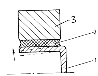
Embodiments of the invention will be described in more detail with
reference to the accompanying drawings in which Figures 1, Z and 3 each show
examples of torsional vibration dampers ready for use, in partial cross
section.
As seen in the Figures, the hub rings 1 are so shaped that
immediately after the w lcanizing step the hub ring 1 and the rubber ring 2
which joins it to the inertial ring 3 take the form indicated in esch instance
by the broken lines. After cooling ~he shape of the hub rings 1 and rubber
rings 2 are changed in the manner indicated by the arrows, so that ultimately
the configuration shown by the continuous lines ls obtained. The shrinkage
tensile stresses in the rubber rings 2 following cooling are largely
eliminated or are replaced by compression pre-stress by this reshaping. It
can be seen in Figure 3 that the inner diameter of the inertial ring 3 is
smaller in the region of rim 4 adjacent annular projection 5 than it is
adjacent the other axial end of the rim 6. The durability of the torsional
vibration dampers ultimately obtained is clearly improved.
PAT 13582-1