Note: Descriptions are shown in the official language in which they were submitted.
- 1 3 ~ 2 ``
Fall-Arre6t Safety Device
This invention relate6 to apparatu~ comprising a
rotatably mounted drum or ~pool on which a rope, cable or
other coilable tie member can be wound, and a braking
mechanism which automatically stop~ or retard6 rotation of
the drum or 6pool if its rotational speed or acceleration
rise6 above a certain value.
Apparatus of this kind can be used, for example, for
safety lowering or fall-arre6t purposes by attaching the
drum or spool holder or casing to a fixture and a~taching
the free end of a safety line, wound onto the drum or
spool, to a person or object to be protected. A
particularly important u6e of such apparatus is for the
protection of a per~on working at high levels above the
ground, u6ing a 6afety line which is attached to a
p~r~onal 6afety belt or harness. Apparatus for such
purpo~e ~u~tomarily incorporates a drum which is
self-winding by spring action so ~hat ~lack in the safety
line is au~omatically taken up and cannot accumulate and
thereby create a further 6afety hazard.
It is important for worker~ using such a fall-arrest
apparatu6 to be warned again6t working with the cable near
to the limit of its pay-out length, becau6e in the event
of a fall the pay-out limit might be reached before the
fall spead has been 6ubstantially decelerated by the
brakee in Which ca6e the fall would ba abruptly arrested
with con6equent high risk of serious personal in3ury.
It i6 known in the art to mark a tail end 6ection of
the cable length 80 that that ~ec~ion i~ vi6ually
identifiable as such as it emerge6 ~rom the drum or drum
housing. Apparatu6 i6 commercially available in which a
,,~
.
- ~ 3 ~ 2
20080-342
tail end cable section of about 1 metre in length is painted red.
The marking of the tail end section oE the cable is
efEective Eor its purpose only lf a watch is kept for its
appearance, either by the worker attached to the safety line or by
another person posted as look-out. This precaution involves
difficulty or inconvenience and it is in practice liable to be
omitted.
The present invention provides more reliable means of
warning.
According to the present invention there is provided
apparatus comprising a rotatably mounted drum on which a rope,
cable or other coilable tie member can be wound, and a braking
mechanism which automatically stops or retards rotation oE the
drum if its rota-tional speed or acceleration in the unwinding
direction rises above a certain value, characterized in that a
guide through which the tie member passes is mounted at a loca-tion
; in the vicinity of the drum; and a stop for abutting said guide is
attached to the tie member near to its tail end and serves by
abutting said guide to resist further pay-out of tie member from
the drum under pulling force up to a certain magnitude; said guide
or said stop being formed or mounted so as to yield and so allow
further pay-out of the tie member under pulling forces exceeding
such limit.
The magnitude of the resistance to pay out of the tie
member beyond the limiting position determined by the stop is a
factor to be selected with due regard to the intended use of the
apparatus. The resistance should of course be high enough to
:~31~7~2
200~0-3~2
prevent passage of the stop under normal working loacls on the
cable.
In the case oE personnel fall arrest safety apparatus,
the said resistance should be high enough -to resist any pull on
the tie member (hereaf-ter called
2a
,, ,,~., . ~ , .;
1 3 ~ 2
, ~
"cable") which the worker i6 likely to exert during normal
working in an attempt to move further away from the drum.
The resistance must thwart any 6uch attempt and therefore
give the worker 6ensible warning that he i~ at the safety
limit of the cable extension. At the same time ~he guide
and/or the stop i6 required to yield in the event of a
worker falling when the cable is at or approaching that
limit. Therefore the yield resi6tance must be overcome
by the smalle6t force which might be imposed in the event
of a worker falling when the cable is a~ or approaching
the said limit. In the case of appara~us intended to be
used as personnel fall-arrest safety apparatu~, it is
suitable for the yield resistance, expressed in term~ of
the steady load which must be applied to the cable to
overcome the resi6tance to further pay--out of the cable,
to be between 50 lbs (or 22.7 Kg) and 150 lbs (or 68 Kg)
and prefe..ably the said resistance is be~ween 80 lbs (or
36.3 Kg) and 140 lbs (or 63.6 Kg).
The yield resi6ta~ce can for example be the
resistance of the guide or the stop to bodily displacement
under pulling force on the cable. For example, the guide
can be held in place by bolts or other fa6teni.ng means
which yields by rupturing. Alternatively the material of
which the guide or the stop is formed and/or i~s geometry
can be such that it fractures or deforms to allow further
pay-out of the cable when a predetermined pulling force is
exceeded.
In preferred embodiment6 of the invention the 6top
can be forced past the guide without breakage or bodily
di~placement of the 6top or the guide or of ~lean6 holding
the 6top or guide in place. There i6 therefors in such
ca6e6 no ri6k of broken or di6placed pieces interfering
with the continued operation of the apparatus.
In the mo6t preferred embodiment~ of the invsntion
the yield occurs by ela6tic deformation of material. The
yield resi6tance can readily be predetermined by the u6e
~ - ~3~ 5~2
4 20080-3~2
o such material and it can have a useful cushioning effect at the
moment of an impact of -the stop against the cable guide.
In one very satisfactory way of carrying out the invention,
the guide comprises elastically deformable material which defines
a guide passage through which the tie member is Ereely movable but
through which said stop can pass only under a force large enough
to cause radial expansion of said passageway by said stop.
Preferably the stop is in the form of a ferrule through which
the cable extends.
The -trailing end portion of the cable, which intervenes
between the cable stop and the point at which the cable is
attached to the drum, should be of sufficient length to ensure
that a falling load can be smoothly decelerated by the drum
braking system during the unwinding of that intervening cable
portion, even if the cable stop encounters the guide right at the
beginning of the fall.
The drum braking mechanism can comprise a centrifugal clutch
via which friction braking forces are applied in the event that
the unwinding speed of the drum exceeds a predetermined value.
The mechanism can be constructed so that co-operating friction
braking components are forced together under a progressively
increasing pressure responsive to the operation of the clutch,
e.g. as described and illustrated in United l~ingdom Patent
1 552 667. Preferably however the braking mechanism comprises
relatively displaceable friction braking components which are
permanently held pressed together, at least one of such components
,~
3~7~2
-4a- 20080-342
being fixed and the other or another of them being displaceable
relative to such fixed component(s) by force which is transmitted
from the drum or spool via the centri-Eugal clutch.
~, :
-` ~L3~7~2
An embodiment of the invention, selected by way of
example, i8 illu~trated in the accompanying drawings, in
which:
Fig. 1 is a part sectional elevation of the
apparatus; and
Fig. 2 i6 a detail view 6howing the cable 6top and
guide on a larger ~cale.
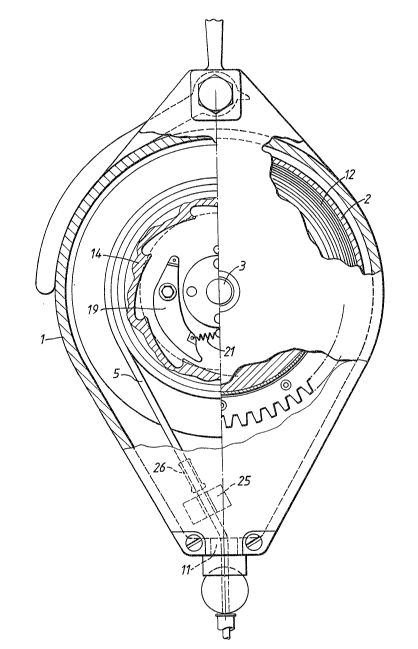
The apparatu~ i~ a so-called 6afety block. ~xcept
for the cable ~top and guide feature of the present
invention, the block i~ basically similar in construction
and function to that described in the aforesaid European
Patent Applica~ion 0 247 818. The block comprises a
casing 1 within which a cable drum 2 is mounted for free
rotation about a ~haf~ 3 the ends of which are supported
by the casing. At the top of the casing there is a
shackle by which the block can be suspended from a fi~ture.
A cable 5 is wound onto the drum 2 and leads out of
the casing via a bottom aperture 11 60 ~hat the free end
of the cable can be attached ~o a per~on or object to be
protected.
By pulling on the cable 5, the drum can be rotated in
the unwinding direction, against the action of a spiral
spring 12 housed within the drum. So long as the
unwinding speed remains below a certain level, the block
offer~ virtually no re~istance to the unwinding of the
cable other than that imposed by that spring. However if
the unwinding speed increa~es to that level, due for
example to a person attached to the cable 5 falling, the
drum becomes arre6ted by a friction brake through the
agency of a centrifu~al clutch mechani6m. This mechani~m
comprise~ pawls 6uch as 19 which are pivotally connected
to the drum. If the drum accelerates in the unwinding
direction due to the fall of a workman attached to the
cable, the pawls pivo~ under the centriEugal force,
i
6 IL ~ 2
again~t the action of 6pring6 21 into positions in which
free end~ of the pawl6 engage behind ratchet teeth of a
friction braking ring 14 which i6 in friction-braking
contact with a co-operating fixed component. The
frictional resistance to rotation of the eing 14 i6 such
that the pay-out speed of the cable is decelerated to zero
at a safe rate.
Between the drum and the cable exit aperture 11 there
is a fixed cable guide 25 through which the cable passes.
The guide define6 for the cable a pas~ageway 2~a which i~
7.0 mm in diameter. The cable diame~er is 5.0 mm. The
guide is made of an elastomeric material: synthetic
rubber, and is a one-piece moulding.
A steel ferrule 26 has been swaged onto the cable at
a position along the cable which i~ about 1.0 m from the
point at which the cable is attached to the drum. The
fe~rule has an outer cylindrical surface 7.0 mm in
diameter but its lower end is slightly enlarged so tha~
the ferrule will not pass through the passageway 25a in
the guide 25 unless the passageway is expanded by elastic
di~tention of ~he passagway wall. The resistance to this
elastic deformation is such tha~ when the ferrule is in
contact with the guide, with the lower end of ~he ferrule
against the guide, and a progre~sively increasing axial
force tending to increase the abutment pressure is applied
to the part of the cable projecting from ~he guide, the
ferrule becomes pulled through the passageway only when
the loading force reache6 100 lbs (or 45.4 Kg).
Thi6 re~i6tance impo6ed by the guide en6ure~ that the
cable will not be pulled beyond thi~ pay-out position by
force6 exerted on the cable in consequence of normal
movement6 of a worker attached to the cable. If the
worker attempt~ to move further from the drum, he will
~en6e the re6i6tance and be alerted to the fact that he i~
at the limit of the regulation working range of the cable.
. .
!
~3~7~2
Should the worker fall when the cable i~ at or near
such limit, the ferrule will be pulled ~hrough the guide
by the applied load but the fall will be decelerated by
the drum brake mechanism so that an abrupt destruction of
kinetic energy l~kely to cause very serious and possibly
fatal injury is avoided.
The trailing (upper) end of ~he ferrule may also be
slightly enlarged so that once the ferrule has been pulled
down past the guide the cable cannot very easily be
rewound without attention being drawn to the fact that the
cable has been pulled out beyond its intended working
limit and that a check should therefore be made that the
apparatus is in serviceable condition.
It will readily be perceived that as an alternative
to the illustrated arrangement, the guide 25 can be a
rigid component and the ferrule 26 can be of elastically
deformable material (which can for example be moulded onto
the cable) so that it can be forced ~hrough the guide by a
cable loading above the predetermined limit.
As a further alternative, the ferrule 26 can be
secured to the cable by pins which shear under a given
cable loading exerted while the ferrule is abutting
against the guide. In this case the guide can of course
be of rigid material.
.. .. . ..... .. .. .. ... . .