Note: Descriptions are shown in the official language in which they were submitted.
~ ~ 3 ~
The invention relates to a modular observation instrument
with rang~ finder. The invention more particularly relates
to a modular, multifunctional observation or viewing
instrument, which is able to function as a monocular
telescope or binocular field glasses, as an integrated range
finder, as a direction meter and optionally further
attachments.
Various instruments are known in a combination of field
glasses or telescope with a fitted in or on range finder, or
provided with a compass. Both types of instrument are
provided for various special purposes. However, none of them
is able to supply a complete three-dimansional information
over the absolute position of a sighted object, e.g. as a
mathematical vector, described by a direct distance
indication with respect to a reference point and two angular
readings (azimuth and elevation).
In addition, geodetic precision range finders using a laser
light source are known. Such instruments are mainly used as
an attachment to existing geodetic equipment. The use
thereof assumes the usage of a target reflector, which
reflects the laser pulses emitted by the instrument. Target
observation or the identification thereof and the actual
measuring process take place in succession.
-- 1 --
131~861
For a generally mobile use field glasses-like, usually
monocular instruments are known having a built-in range
finder. Generally the optical path of the range ~inder is
separate from that for the visual observation of the object.
Separate, complicated æpecial optics are used for each part,
i.e. for the visible light on the one hand and the
observation light, generally infrared light (IR) on the
other, so that such instruments have a relatively high
weight. The conventional restriction to a single observation
channel ~monocular) impairs the coverage for the observer and
rapidly leads to fatigue.
The problem of the present invention is to provide a modular
observation
X - la -
6 1
instrument with range finder in such a way that it also
permits the tracking of an o~ject and offers a significant
constructional simplification with the aim of an optimum
rational use of the lenses required for the system, so as to
in this way be able to save weight and provide a much lighter
instrument. In order to be able to clearly determine the
coordinates of an object to be tracked, apart from the range,
also the two angles azimuth and elevation are to be measured.
In addition, an undisturbed, continuous and easy visual
observation of an object is to be ensured and, independently
thereof, a very precise location measurement is to be
possible at any time, whose true and optionally corrected
result can be read off simply and reliably, without visual
observation having to be interrupted. To ensure the
. 15 efficiency and comfort for visual observation, a binocular
instrument is sought.
According to one aspect of the invention there is provided a
modular observation instrument comprising a casing
containing; an optical viewing device having an erecting
prism and having a first optical path defined by a plurality
of optical elements; a range finder having a second optical
path defined by said optical elements; a direction meter for
the azimuth and elevation; at least one computer module
having a keyboard for simultaneously triggering the range
finder and the direction meter; the erecting prism being
provided with selective splitting means for splitting the
light into visible light and infrared light.
A preferred embodiment of the invention comprises a modular
observation instrument with binocular field glasses and a
range finder integrated in a casing with an infrared
transmitter and an infrared receiver, in which the infrared
optical path of the range finder is passed over the same
optical elements which determine the optical path of the
field glasses, into the instrument casing are additionally
t ~ - 2 -
~31~8~i
integrated a direction meter for the azimuth and elevation
and at least one computer module for the functional control
of the measuring processes and means are provided for
simultaneously triggering the range finder and direction
meter, the optical path of the visible light remaining
undisturbed for the field glasses function during this
measuring process, so that the visual representation of the
measured object is unimpaired during the measuring phase.
Suitably means are provided for repeating the measuring
process of range, azimuth and elevation at predetermined
intervals and for calculating the vectorial object speed from
the thus obtained measured results.
In one embodiment of the present invention the instrument has
at least one erecting prism associated with the field
glasses, in
.~
- 2a -
131~
which the erectlng prism is provided with selectively reflecting
means for splitting up the combined optical path into visible and
infrared light directly upstream of the infrare~ transmitter or
the infrared receiver. Suitably a beam splitter is fit-ted to the
first reflecting face of the erecti.ng prism when considered from
objective or lens, so that the interface between the two
components is transparent for the infrared light used, whils-t the
visible light is reflected in undisturbed manner. Desirabl~ one
of the two telescope optics is set up as an infrared transmission
channel and the second telescope optics as an in~rared reception
channel, a second beam splitter being fitted to the second
erecting prism of the field glasses located in the infrared
transmission channel and by means of which takes place the direct
fading of the infrared transmission radiation into the combined
optical path in the direction of the second lens, accompanied by
the simultaneous fading of the infrared radiation out of the
optical path leading to the second eyepiece. Suitably there are
switching means for stabilizing the transmitter in order to
ensure the transmission of the directional pulse at a precisely
defined time delta t following the application of the triggering
pulse.
In another embodiment of the present invention the range finder
and the direction meter have autonomous computer modules, whose
outputs are combined in common display means. Suitably there is
a common display means re~lected into the o~tical path.
Desirably the output of the computer modules are connected with
an interface to external signal processing means. Suitably the
interface also has connections for the remote initiation of
instrument functions.
A decisive advantage of this instrument is the common optics for
visual observation and ranging. Thus, the system is simple and
is free from excess glass weight. For ranging with pulsed IR-
light, use is made of the same optics as for visual observation.
A further decisive advantage of the instrument is that its
-2b-
t~ .
~ 3 ~
multiple function, in particular -the ~hree funckions visual
observation, ranging and direction determination can be activated
precisely at the same time and not alternatively and
successively. This leads to decisive advantages, particularly
with respect to the precise tracking of moving targets. The
tracking result can be given in absolute coordinate values, if
the actual position is known. Through the combination of the
individual measures an extremely handy and easily usable
instrument is provided, which has a much higher usage value than
the hitherto known instruments. The complete combination of said
three functions in the case of corresponding design, makes this
instrument a highly accurate position finder.
The invention is described in greater detail hereinafter relative
to nonlimitative embodiments and the accompanying drawings,
wherein show:
-2c-
-
~ 3 ~
- 3 -
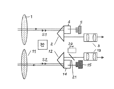
Fig. l the optical path of a binocular observation instrurnent, with
tlle representation of the most important optical components.
Fig. 2 the receiver channel according to fig. 1 in slde view.
Fig. 3 the bloclc diagrarn for the electronic par~ of the instrument
according to figs. 1 and 2.
The principle of the invention is essentially based on ~lle possibllltyof being able to integrate several functions into one instrument, said
instrument having the handiness of field glasses, so that it can be
permanently carried by the interested user. Preferably at least three
functlons are integrated lnto the instrument, namely the tradltlonal
field glasses or telescope func~lon, whlch permits a direct observation
of an object, as well as the higl-ly accurate range finding integrated
into the observation optical path and as the third function a direction
indication also integrated into the instrument and whose result, namely
azimuth and elevation~ is additionally projected in the observation
optical path. Range and direction measurements can also be transferred
to other instruments or, so as to be visible for third parties, can be
displayed on the outside of the instrument.
In the present case, a modular construction of the instrument means that
it can be designed as a monocular or binocular instrument and that the
direction meter can, if deslred, be integrated lnto the lnstrument. The
instrument concept permits an adaptation to the particular equipping level
in accordance with the desired intended use.
preferred embodiment for illustrating the invention is constituted by
the hereinafter described binocular observation instrument, in which one
visual channel is additionally used for the transmitter and the other for
the receiver of the range finder. ~ccording to fig. 1, it comprises a
conventional Eield glasses part with a lens or objectlve 1, an erecting
prism 2 for laterally correct imaging and an eyepiece 3. The second
optical path also shown in the selected e~lbodiment correspondingly cont-
ains a second lens or objective ll, a second erecting prism 12 and a
second eyepiece 13. In the two optical paths the path of the visible
1 3 ~
-- 4 --
light is indicated by double arrows Sl and SZ. Where necessary, the
participating optical faces for the visible range and ~or the range of
the measuring radiation used, l.e. in the infrared range for example
have been coated.
~dditional components provided in the first optical path are a beam
splitter 4 connected to the first erecting prism 2 and a IR-receiver 5.
The beam splitter fades the measuring radiation used ~or the ran~e Elnd-
ing out of the combined optical path, so that said part of the radiation
does not pass into the first eyepiece 3, except for a residual part which
is harmless to the eye. The arrangement of the beam splitter 4 is shown
in side view in fig. 2. The interface between beam splitter 4 and erect-
; ing prism 2 is provided with a filter layer, which is transparent for the
IR-light used, but reflects visible light, so that the traditional effect
of the erecting prism remains unchanged for the visible light. Thus,
beam splitter 4 is not only used for separating visible and ~R-llght,
but also for protecting the human eye against laser radiation.
~part from the conventional components, the second optical path contains
a trnnsmitter 15 ior emitting infrared measurement pulses, as well as a
second beam splitter 14 combined with the second erecting prism 12. The
arrangement of the second beam splitter 14 corresponds to that of the
first beam splitter 4 on the first erecting prism 2.
In the preferred embodiment, the IR-light used has a wavelength of approx-
imately 900 or 1500 nm, as a function of the laser type used. The IR-trans-
mitter comprises e.g. a pulsed or a modulated crystal or semiconductor
laser, whosc trnnsmission capacity is sclected in such a way that it
relinbly remains within the range protecting the eye, but bridges the
desired range. This is optionally achieved by a special signal processing
method, which does not form the subject matter of the present invention.
The optical path of the transmitter can in special cases, e.g. when des-
igning the instrument as a monocular observation instrument, al90 be led
to the outside by a separate optics. In the present case, the reception
channel for the IR-radiation is identical with that oE the described
instrument. Semiconductor lasers or flash lamps can be used for pumping
~5~
-- 5 --
the crystal laser.
The second beam splitter 14 ensures the direct fading of the infrared
rndi~ion in~o the conventional erecting prism 12 in thc direction of
the second lens 11, accompanied by the simultaneous fading of said
radiation out oE the visible optical beam path S2 leading to the second
eyepiece 13. By means of the second lens 11, IR-radiation is transmitted
in the direction of the object to be measured. The radiation reflected
by the object reaches the instrument via the first lens 1, from where
it is passed to the first erecting prism 2 and is faded by the first
beam splitter 4 out of the combined optical path and is passed to the
IR-receiver 5. Unlike in conventional range finders, there is no need
to supply the receiver with part of the transmission pulse for fixing
the time origin, because corresponding circuitry improvements are prov-
ided in the electronic part. These are essentially formed by stabilizing
means, which ensure that the directional pulse is always emitted at a
precisely deEined time delta t after the application of the triggering
pulse. Thus, there is no need for conventional optical cross-connections
between transmitter and receiver.
In the simplest case, the IR-receiver 5 can comprise a photodiode and can
be integrated together with an amplifier to form a hybrid. Further inte-
gration with the analog-digital converter to form an extended hybrid is
also possible.
~part from the conventional means, there is also a readout or display 20
and a partly reflecting mirror 21 for reflecting the display values of
tlle range finder and direction meter into the optical path to the eyepiece.
On the outside of the instrument it is also possible to provide an auxil-
iary display 22.
Finally, there is an assembly 30 for determining the direction of the
object to be measured and which will be explained hereinaEter relative
to fig. 3.
~3~$~
-- 6 --
~11 the aforementioned parts are placed in a common casing, which is
e.g. constructed in similar manner to a conventional casing for field
glasses. Despite the additional functions, the observation instrument
is extremely handy.
Fig. 3 shows the electronic part and also the functionaL construction
of the instrument. In the upper part is provided the range finder and
in the lower pnrt the as yet to be described assembly for determining
the direction of the sighted object. In principle, the range finder and
direction meter are autonomous and are equipped with their own computers.
Tlle outputs of the two assemblies- are led to the common display 20 which,
according to fig. 1, is faded into the optical path of preferably only
one observation channel.
The display of the measured results takes place in the viewing field ofthe observer and through the readout of the measured results the visual
observation process of the object does not have to be interrupted. The
measured results can also be displayed on the outside of the instrument.
Switching means for producing the different feed voltages, as well as the
batteries are not shown in the drawing.
There is also a keyboard 40 common to the two instrument parts and which
is fitted to the outside of the instrument at a readily accessible point.
It is used for initiating the different functions of the instrument and
for inputting data. It is positioned in such a way that the observation
process is not disturbed during operation. Finally, the instrument can
be provided with an interface connection 50 which, according to the
preerred embodiment, is also connected to the output of the two instrument
parts. The interface can e.g. be standardized and can permlt the connec-
tion of the instrument to data transmission means or directly to a computer
or mass memory. It can also be used for remotely triggering instrument
functions.
The assembly of the range finder with IR-transmitter 15 and IR-receiver5 is connected to a computer module 6, particularly a microprocessor.
~ 3 ~
It is preferably an autonomolls mini computer, which is pro~ided with aROM 7 for storing the programs for controlling the assemblies belonging
to the range finder and for the exec-ltion of the individual calculating
operations. There is also a memory area 8, which is used for the storage
oE c1a~n, wllicll c~n on ~hc onc llnn~ ~e prc(lctcr~ ncd cons~nnl:s or rc~crcncedata, e.g. reference coordinates and on the other hand storage locations
for storing measured results until they are e.g. polled by interface 50.
The IR-receiver is connected to computer 6 across an analog-dlgital
converter 9, the distance being calculated from the signal travelling
time. ~s a function of the strength of the signal, individual pulses
or pulse sequences are evaluated. Through repeated ranging at short
time lntervals, it is possible to measure the speed, particularly the
radial speed of the target object.
The second assembly, shown in the bottom part of fig. 3, is a device for
direction determination purposes, such as e.g. known from ~P-85 902 429.1.
This device, which is also known as an electronic compass, contains mag-
netic sensors 31, tilt sensors 32 and a temperature sensor 33. All three
of the latter components are connected across a multiplexer 34 and an
analog-digital converter 35 to a second computer 36, particularly a micro~
processor. The latter is also equipped with a ROM 37 and R~M 38. On
computer 36, it is possible to see the aforementioned connections to dis-
play 20, to keyboard 40 and optionally to interface 50.
In computer 36, the measured data are corrected by means of stored corr-
ection tables and by incorporating complimentary and/or redundant sensor
informations. Systematic incorrect instructions and interference as a
result o temperature influences, declination, installation environment
oE the sensors, sloping position, movement, etc., are consequently elimin-
ated. Only true quantities are displayed, e.g. the azimuth and elevation.
In addition, plausibility criteria for all the measured values are prog~
rammed in the computer system and they filter out random or temporary
disturbances. Computer 36 of the direction meter can also assume addition-
al overriding control functions. ~ digital-signal processor (~SP) is
particularly advantageous as the range Einder computer 6.
- c3 -
F~ LL~ 1. ly, Iu.! Ill~`CI!;U r.Lllg ~ llC i.l) ~ [ L~ i. I'(.'CI: i.OII Ill~!t (`1' i. ': 1)~1';(`(1
on deterrnining the terrestrial magnetic fieLd by means oE magnetic sensor
31 and to correct the measured result with the aid of slope or tilt
sensors 32. Finally, using ~he temperature sensor 33, Lhere i9 a comp-
ensation of measuring errors caused by temperature changes. 'I'he mag-
netic field sensors can be constituted by elements, which are based on
the ~lall effect, which incorporate the principle of a field plate, or
give rise to a res;stance change, which is then determined with the aid
of a bridge circuit.
Measurement with the aid of a dynamic signal is also possible, which issupplied to the sensor briefly and in alternating manner, e.g. in the
fonn of a Eurtller magnetic fielc!. The difference of the thus obtained
magnetization or the time necessary in order to assume the original
position is detennined. The result is a measure for the position of the
sensor in the terrestrial magnetic field. Thus, the components of the
terrestrial magnetic field and the gravitational field are measured and
the azimuth and elevation of the optical axis of the'instrument are
calculated therefrom in computer 36, whilst taking account of the stored
correction values.
The measured values of the magnetic field sensors are amplified, digitized
and processed in computer 36. Details of this device are described in
detail in the aforementioned EP-OS ancl are not shown again here. As des-
cribed therein, an azimuth measurement performed using said assembly is
position and also tilt-independent through the incorporation of tilt sen-
sors. In order that the measurement also takes place in an acceleration-
independent manner, as from a given rotation angle, there is an automatic
switching to the magnetic field sensors for tilt measurement purposes.
The tilt change in space can be calculated by computer 36 and namely as
a result of the identification of different and/or uniform signal changes
of the magnetic field sensors 31 and by comparison with a previously
stored desired value curve.
As a result of the time change of the sensor signals and therefore o~ the
three components of the target vector, it is possible to calculate the
~ 3 ~
vectorial speed oE the target object relative to the observer if the-re
ls an instrulnent Eollow-~lp ~y tl~e latLer.