Note: Descriptions are shown in the official language in which they were submitted.
~31 ~98~
PAR~IAL PRESS IN GRAVITY BENDING FURNACE
Back~ he Invantion
l. Field of the Invention
_
This invention relats~ to sag bending of glass sheets on
bending irons and in particular to a method and apparatus for press
bending selected portions of the glass sheets on bending irons while
moving through a heating lehr.
`~
2A. Technical Considerations
In the practice of sag bending to form shaped glass windows for
automobiles and llke, as disclosed in V.S. Patent No. 4375978 to Reese,
glass sheets are positloned on and supported by a skeletal bending mold.
The shaping rail o~ the mold has a shape and configuration similar to
that of the shaped glass sheet at a locatlon slightly inboard of its
periph~ral edge, The bending molds are then conveyed in succession
through a heating lehr where the glass sheet i8 heated to its deformation
temperature such that lt begins to sag by gravity until the glass sheet
conforms to the configuration of the shaping rail. After the glass ~heet
~` ~ i8 shaped, the mold iæ conveyed through an annealing ~one where the glass
sheet Is cooled in a controlled manner from its deformation temperature
through its annealing range to anneal the glass shePt.
; The glass sagging technique has been the method used to bend
two glass sheets, or doublets, simultaneously, which æheets are
~subsequently laminated together to form a laminated automobile
windshleld. The windshield is curved to conform and blend into the shape
of an automobile vehicle in which it is installed.
-- 1 --
~ 3 ~
A critical shape parameter of curved glass sheets used for
windshields is the approach angle of the glass sheets along the A-post of
the vehicle body. The approach angle is the angle at which the
windshield meets the vehicle body at the gerlerally vertically extending
A-posts of the window frame. It has been found that in sag bending glass
sheets with a deep sag or reverse curvature, there is a tendency for the
sheets to draw glass from thelr longitudinal end sections. As a result,
the gla~s sheets may tend to lift off the end rail sections of the
outline bending mold and have reduced curvature causing the sheets to
deviate from desired shape and tolerances. This deviation may also be
caused by overheating the outer areas of the glass sheet to achieve
proper curvature along the outer edge of the longitudinal section of the
glass sheet to achieve the desired curve confi~uration.
As automotive styllsts strive for more aerodynamic designs, the
windshields are assuming more co1nplex and deeper bend configurations. In
add:Ltion, the windshield edges are approaching the A post of the vehicle
body at a more flush fashion to provide a smoother transition between the
windshield surface and the vehicle body surface. As the windshields
design~ become more complicated with compound and reverse curvatures,
these shapes are becoming increasingly difficult to control during
conventional sag bending operationR.
It would be advantageous to develop a method of forming glass
sheets incorporating conventional sag bendlng techniques with other
shaping techniques so as to form and m~intain the desired configuratlons
required for proper vehicle assembly.
131~
2B. Patents of Interest
__
U.S. Patent No. 3,220,819 to Jenderisak teaches a hold-down
device for a glass bending mold. Glass doublets are positioned on an
outline mold and hold-down devices mounted along a selected edge of the
bending mold ex~end over the glass doublet edge and hold the peripheral
portion of the glass doublet against the underlying shap~ng rail. As the
glas* sheet is heated, the end section of the mold pivo~s relative to ~he
main portlon to shape the heat softened glass sheet while the hold-down
devices maintain the glass doublet edge agalnst the shaping rail.
U.S. Patent No. 4,265,650 to Reese et al. teaches the press
bendlng of windshield doublets between a pair of vertically aligned upper
and lower, full surface press faces. Glass sheets are positioned on an
outline shaping mold and conveyed through a heating lehr wherein the
glass sags by gravity to conform with the mold outline. The mold is then
stopped and positloncd between the press faces and the lower press face
lifts the glass sheets off the outline mold and sandwiches the sheets
aga~nst the upper press face. After shaping, the lower press face
redeposits the glass sheets on the outline mold for continued downstream
movement.
U.S. Patent No. 4,496,386 to Hymore et al teaches a method and
apparatus for bending glass sheets. The apparatus includes a lower
outline press member having an array of spaced apart shaping rail
elements mounted to pass upwardly between ad~acent conveyor rolls to
con~act and support the undersurface of the heat softened glass sheet. A
second array of shaping rails is disposed above the conveyor rolls,
mounted for movement into and out of association with the spaces between
the spaced apart lower shaping rail elements. As the glass sheet is
.
- 3 -
~3~3~
raised by the lower shaping rail and pressed against an upper shaping
rail, the second array of shaping rails contact the under~urface of the
glass sheet between the first shaplng rails to press the peripheral edge
of the glass sheet against the upper shaping mold.
U.S. Patent No. 4,501,603 to Frank et al teaches a method and
apparatus for shaping glass sheets to complicated shapes. Heat softened
glass sheets are lifted o~f o~ conveying rolls by a lower, slatted
pressing mold and pressed against a full surface upper vacuum mold. A
moveable shaping rail mounted on the upper vacuum mold engages the lower
surface of the end portion of the hot glass sheet to sandwich the latter
against a correspondlng end portion of the upper vacuum mold to shape the
glflss sheet in the desired complicated configuration.
This disclosure provides an apparatus for shaping heat softened
glass sheets supported on a shaping rail of an outline bending mold. The
apparatus includes a pressing member supported on a frame and a biasing
arrangement to move the pressing member from a first position wherein the
pressing member is spaced ~rom selected portions of the glass sheet to a
second position wherein the pressing member i9 biased against the glass
sheet. In the pre~erred embodiment of the invention, the bending mold
with the glass shee~ supported thereon is conveyed downstream through a
heating lehr and the pressing member i8 provided with an sliding
arrangement wherein the presslng member moves downstream with the glass
sheet. The movement o~ the pressing member i8 synchronized such that
there is no relative horizon~al movemen~ between the glass sheet and the
pressing member in the direction in which said bending mold is mo~ed
through said lehr when the pressing me~ber contacts the glass sheet.
~.
~31~
In one particular embodiment of the invention the pressing
member i~ supported by a pivoting frame that is linked ~o Q piston member
that rotates the frame and moves the pressing member from the first, non-
engaging positi~n to the second, glass sheet biasing position. In
additlon,a controller controls the downstream movement of the pressing
assembly and the pivoting actiorl of the frame to ensure that there is no
relative horizontal movement between the pressing member and glass sheet.
In an additional embodiment of the invention, an arrangement is
provided to translate the pressing member in a generally horizontal
direction transverse to the conveyed direction of the glass sheet through
he lehr.
o~qQ
A This~ir~we~rt also provides a method of shaping selected
portions of a glass sheet supported on a shaping rail of a bending mold.
The mold ls con~eyed through a heating lehr to heat the sheet to its
deformation temperature wherein the glass shee~ sa8s by gravity and the
perimeter the glass sheet substantially confirms to the shape of the
shaplng rails positioned slightly inboard of the glass ~heet perimeter.
A selected surface portion of the hot glass sheets is contacted with a
shaping member having a sheet engaging surface with the desired shape of
the glass sheet at the selected surface portion. The ~ember ~s biased
against the selected surface portion to conform ~he surface portion of
the glass sheet to the sheet engaging surface of the shaping member. The
shaping member is conveyed along the lehr such that there is no relative
hori~ontal move~ent between the shaping member and the glass sheet in ~he
direction in whlch the glass sheet is conveyed through the lehr as the
shaping member contacts the glass sheet.
-- 5 --
~31~9~6
Brief Desc_ption of the Drawi~E~
Figures lA and lB are longitudinal side views of a typical
bending lehr showing the loading, hPating, shaping, annealing and
unloading sections.
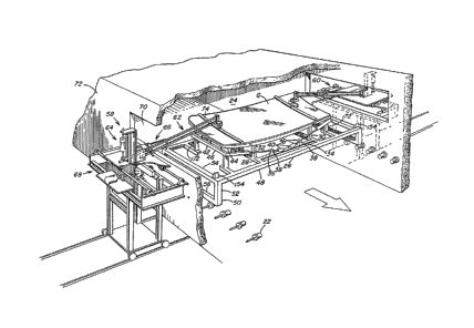
Figure 2 i9 a prospective cross sectional view taken through
the shaping station of the lehr along line 2-2, showing hot glass sheets
supported on an outllne ring mold and the preferred press assembly of the
present invention, with portions removed for clarity.
Figure 3 is a side elevational view of the press arrangement
illustrated in Figure 2 with portions removed for clarity.
Figure 4 is a rear elevational view of the press arrangement
illustrated ln Figure 2 with portions removed for clarity.
Figure 5 is a view through line S-S of Figure 3.
Figure 6 is a schematic illustrating the approach angle of the
glass sheet at the shaping rail of the outline mold, with and without the
pressing arrangement o the present invention.
Figure 7 is an alternate embodiment of the present invention.
Descr~tion of the Preferred Embodiment
Referring to ~igures lA and lB, there is shown a heating,
shaping and annealing lehr for shaping glass sheets. The lehr begins
downstream with a loading zone 10 and includes an initlal heating zone 12
of tunnel type configuration, a gravity bending zone 14 downstream of the
initial heating z~ne 129 an annealing zone 16 and a cooling zone 18 in
end-to-end relation in the downstream portlon of the lehr. An unloading
zone 20 is positioned beyond the lehr.
~ 6 --
1 3~5~
A conveyor, comprised of a plurallty of stub rolls 22 di6posed
ln transversely opposing, longitudlnally spaced relation, extend the
entira length of the lehr and defines a path of movement along a
longltudinal reference llne. As illustrated in Pigure 2, each stub roll
?2 is ~ounted on a shaft tha~ extends through a side wall of the lehr and
is connected to a conveyor drive means (not show~). The conveyor may be
divlded lnto a number of sections, each driven from its own drlva means
through conventlonal drive rod and gear means or chaln drives, or the
conveyor sectlons may be driven from a common drlve through clutches in
any manner well known in the art.
The lehr lncludes a plurality of glasq support molds 24, one of
which is sho~n in Flgure 2, each bein~ supported by a mold carrier 26.
Although not limited in the present invention, the particular mold 24
illustrated in Fi~ure 2 i9 similar to the mold disclosed in U.S. Patent
No. 4,626,267 to Reese, and is an articulating mold with pivoting end
sections. The mold 24 includes a pair of crossbars 28 which support a
number of vertical posts 30 which in turn support the ends of
longitudinal shaping rails 32. The surface contours of the shaping ralls
32 conform to the shape desired along the longitudinal edges of the glass
sheet G supported for bending on the mold 24. Longitudinal members 34
interconnect the crossbar~ 28. Mounted on members 34 are hinged support
posts 36, each of which supports a hinge 38 which includes a weighted
lever arm 40 adaptable for pivoting in a substantially vertical plane
about an axis defined by the a~sociated hinge 38.
The mold 24 i9 also provided with two pivot~ng end mold
sections 42. Each of the end mold sections 42 comprises an end rail
..
~ ~ 7 _
~31~g~
section 44 whose upper edge forms a surface conforming in elevation and
outline to the shape desired for one or the other end portion of the
glass sheet G to be shaped on tha mold 24. Each end mold seetion 42 also
includes an outrigger 46 attached to the undersurface of the end rail
section 44~ The outrigger 46 extands outward of the end mold section 42
towards one of the hinges 38 and is attached to the weighted lever arm
40. When the glass sheet becomes heat softened, the lever arm 40
pro~ides a closing pressure that causes the end mold sections 42 to pivot
from a spread position in which they support the rigid, flat glass sheet
G into a closed position where the upper edges of the end mold sections
42 form continuations of the shaping surfaces provided along the upper
edges of the shaping ralls 32 so that the shaping rails 32 and 44 form a
contlrlllous outline shaping surface to which the glass sheet conforms when
shaped.
Cross support beams 48 are mounted on mold carrier 26 with end
portions rigidly attached to rigid end frame 50, which includes vertical
posts 52, upper carriage rail 54 and lower carriage rail 56. The lower
carriage rail 56 rides on the driven stub roll6 22 of the lehr as the
rolls convey the mold 24 through the lehr as previously discussed.
Flgure 2 shows press assemblies 58 and 60, whlch are the
Bub~ect of this invention, as they are positioned in the lehr relative to
the support mold 24 and carriage 26. The assemblies 58 and 60 are
similar in conseruction. The following discussion will be directed to
the assembly 58 with the understanding that the discussion is applicable
to assembly 60 unless indicated otherwise.
Referring now to Pigures 3 and 4~ the press assembly 58
includes pressing device 62 to contact the glass sheet G, a positionlng
~ 3 ~
and biasing means 64 to maintain the pressing device 62 in contact with
the glass sheet G and actuating means 66 to activate the positioning
biasing means 64 and a support stand 68.
The pressing device 62, which contact~ glass sheet G while the
glass sheet move through the lehr supported on the mold 24, is inserted
lnto the lehr through opening 70 in lehr wall 72, and includes a glass
contacting pres~ member 74 mounted on one of the short sides of a
parallelogram ~haped linkage assembly 76. The linkage assembly 76, which
is comprised of an upper ann 78, a lower arm 80 and a press member
: support bracket 82, has corresponding ends of the upper arms 78 and lower
arm 80 pivotally connected to the bracket 82 and the supp~rt stand 68,
preferably by nut and bolt assemblies 84 and 86, respectively, such that
the upper arm 78 is generally parallel to the lower arm 80. If required,
cooling fluld (not shown) such as air may be circulated through arms 78
and 80 to control their tempera~ure while within the lehr. In the
particular embodiment illustrated in Figure 3, the braclcet 82 includes
side plates 88, only one of which is shown in Figure 3, to which nut and
bolt assemblies 84 attach tha bracket 82 to the upper arm 78 and lower
: arm 80, snd cross plate members 90. Press member 74 is preferably
pivotally connected to the lower portion of the bracket 32 in the manner
to be discussed later. If required, a spring 92 may be positioned
betwe~n upper arm 78 and lower arm 80, as shown in Figure 3, to remove
~ any slack in the assembly 76.
; Although not limited in ~he present invention, in ~he
particular embodiment illustrated in Figure 3, press member 74 is a
~ curved pipe member 94, constructed from a heat resistant material, such
:`
as stainless steel, which contacts the shaped glass shPet G along a
-- 9 --
contact line to impart additional shaps to the glass sheet. The lower
glas.s sheet contacting surface 96 of the pipe member 94 corre~ponds to
the desired curvature of the glass sheet G along the line at which the
pipe 94 contacts the glass sheet. It should bP appreciated that the
glass contacting surface 96 of pressing member 74 may be such that it
contacts large portions of the glass sheet surface and, if required, the
entire glass sheet surface. Pipe member 94 is preferably pinned to the
bracket 82 such that i~ may rotate about a horizontal axis generally
perpendicular to the longitudinal axis of the pipe member 94 whlle being
prevented from being rotated about a vertical axls at the end of the
linkage assembly 76. This pinned connection 98 allows the pipe member 94
to be self aligning as lt contacts the glass sheet G so that the press
member 94 will operate effectively even if the entire contactlng surface
96 of the pipe member 94 doe6 not contact the glass sheet G surface
simultaneously. If the curved conflguration of the glass sheet requires
that the entire contacting surface 96 of the press member 94 contact the
glass Rheet slmultarleou~ly, the press member 74 may be fl~ed to the
bracket 82 at the requlred orientation.
In the partlcular embodlment of the lnvention lllustrated in
Flgures 2 through S, the press member 74 ls a pipe section that provides
line contact between ehe glass sheet and the pipe surface. It is obvious
that the pipe member 94 may be replaced by a partial press face, as shown
ln Figure 7, with a shaping surface which contacts a selected area of the
glass sheet as will be discussed laeer. The press surface may be
con6tructed fram any heat resistant materials such as stalnless steel,
meehanit~ or ceramics.
~ 10
1 3 ~
Referring now to Flgures 3 and 4, the support stand 68 includes
a pair of spaced channel members 100 with upper arm 78 and lower arm 80
rotatably positioned therebetween to allow pivotlng movement about nut
and bolt assembly 86. The channels 100 are positloned on mount1ng plate
102, which is secured to sliding base plate 104 in any conveni~nt
fash1on. The llnkage assembly 76 ls pivoted by the positioning and
blasing means 64, whlch preferably is a pneumatlc or hydraulic cylinder
106 mounted from support plate 108 of the support stand 68, with piston
rod 110 of cylinder 106 plnned to an extended portlon of upper arm 78.
As the piston rod 110 of the cylinder 106 retracts, arms 78 and 80 rotate
about nut and bolt assemblies 86, translating into a clockwise rotation
of the linkage assembly 76 about the support stand 68 and a downward
movement of press member 74 as shown in Flgure 3. When the piston rod
110 moves out of the cyllnder 106, the previously described action is
reversed and the linkage assembly 76 pivots counterclockwise about nut
and bolt assemblies 86.
Although cylinder 106 is preferably a pneumatic or hydraulic
cylinder, it ls obvious to one skilled in the art that other positioning
and biasing me~ns may be used, i.e., a cam and spring or a motor drlve
arrangement.
With continued reference to Figures 3 and 4, support stand 68
further includes a support carriage 112 which includes post members 114,
slidlng rail suppor~ members 116 and 118, and shaft suppGrt blocks 120
mounted on support members 118 to support sliding rails 132. The rails
122 extend in a longitudinal, downstream direction relative to the lehr
and are slidably captured by shaft collar members 124 mounted to the
bottom of slidlng base plate 104. Plllow blocks 126 are muunted to the
top of two of the posts 114 to support drlve shaft 128 of press assembly
drive arrangement 130. The drive shaft 128 includes a gear 132 which
meshes wi~h gear rack 134 secured to the underside of sliding base plate
104. Motor 136 drives shaft 128 so that base plate 104 supporting
pressing device 62 and positioning and biasing means 64 of the press
assembly 58 mo~es longitudinally along rails 122. The motor 136 of drive
arrangement 130 is preferably a reversible drive which is capable of
driving the base plate 104 bo~h upstream and downstream relative to the
lehr. As an alternative, multlple motors or a clutch arrangement may be
used move ~he press assembly 58 along the lehr.
Posts 114 are mounted on wheels 138 which ride on rails 140
which are generally perpendicular to the lehr. This arrangement allows
the press assembly 58 to be moved ;Eurther into or wlthdrawn from the lehr
so a8 to properly position the press members 74 relative to the traveling
glass shee~ G,
Due to the geometric properties of ~he linkage assembly 76
which i8 a parallelogram, i.e., a four-sided figure with opposite sides
parallel and equal, as the linkage assembly 76 is rotated by cylinder
116, it maintalns ~ parallelogram shape and the orientation of press
Dember 74 remalns constant. The nut and bolt assemblies 84 and 86
maintain corresponding points on the upper arm 78 and lower arm 80 at
support stand 68 ln an orientation, one vertically disposed abo~e the
other so that the orientation of bracket 82 also remalns vertical as the
assembly 76 rotates. Since the press member 74 is pinned to the bracket
82 as discussed supra, the orien~ation of the member 74 remains fixed.
It should be noted that press member 74 may also be pinned to
the bracket 82 such that lt freely rota~es about a horizontal a~is
~ 12 -
generally aligned with the longltudinal axis of the lehr. With such a
mounting arrangement, the configuration of linkage assembly 76 may be
such that bracket 82 does not have to remain vertical when assembly 76
rotates since the press member may pivot about the axis and maintain the
proper orientation for engagement with the glass sheet G.
As an alternative to the parallelogram shaped arrangement of
linkage assembly 76, a single pivoting arm member may replace arms 78 and
80 with the press member 74 being pinned to th~ end of the single arm
(not shown). Sllch a member must be sufficiently rigid to support press
member 74 for accurate tracking of and ~ngagement by the press member 74
relative to the movlng glass sheet G.
The cy1inder 106 is activated by actuator means 66 which
initiates the pressing cycle. In the particular embodiment illustrated
in the Figures 3 and 5, elongated, L-shaped, pivoting trlp arm 142 is
mounted to the underside of base plate 104 by pillow blocks 144. End 146
of the trip arm 142 i8 positioned within the lehr and extends downward
with a tip portion 148 generally aligned with and terminating ad~acent ~o
the upper surface 150 of the upper carriage rail 54 of the rigid end
frame 50. As the mold carriage 26 is conveyed through the lehr, the tip
portion 148 contacts a trip plate 154 mounted at the do~nstream end of
the upper rail 54 of the carriage 26 causing the trip arm 142 ~o rota~e
clockwise, as viewed in Figure 5, about an axis defined by the pillow
blocks 144. This rotation of the ~rip arm 142 rotates a tab 156 of the
trip arm 142 into contact with the microswitch (not shown) positioned in
close proximi~y to the tab 156, which in ~ur~ activates a timing sequence
in con~roller 160 (shown in Figure 3 only). The controller 160 controls
the downstream movement of the press assembly 58 via motor 136 and the
- 13 -
plvoting action of the linkage assembly 7S via cylinder 106 as the mold
24 continues to move through the lehr with the heat softened glass sheets
G supported thereon, as will be discussed later.
It is obvious ~o one skilled ln the art that there are other
ways well known in the art to activate the cylinder 106 and motor 136
rather than using a trip arm 142. For example, light or temperature
sensors may be used to locate the e~act position of the support carriage
26 within the lehr and initiate a timing sequence to activate and
deactivate cylinder 106 as well a activate and reset the drive
arrangement 130.
The press asflembly drive arrangement 130 moves the linkage
asse~bly 76 with the pressing member 74 attached thereto along with the
moving mold 24. The controller 160 matches the speed of sliding base
plate 104 with the n~old support carriage ~6 as it travels through the
lehr so that there is no relative movement between the press member 74
and the glass sheet G. In glass sheet configuratlons where it is
critical that the press member 74 contact the glass sheet G at a precise
location on the glass sheet, the mold 24 with the glass sheet supported
thereon may be aligned and squared wl~hin the lehr prior to it being
contacted by the pressing member 74. The mold 24 may be aligned in any
convenient fashion, such as that disclosed in U.S. Patent No. 4,290,796
to Reese et al.
As discussed earlier, the heat softened glass sheets G tend to
draw glass for the longitudinal end portlons durlng sag bending. As a
result, the peripheral portions of the glass sheet G tend to flatten out,
i.e. the curvature of the glass sheets about its periphery, and in
particular along the A post, is reduced. Referring ~o Figure 6, line 164
- 14 -
~ 31 ~
represents the curvature of the glass sheet from a conventional sag
bending operation. As taught of the present invention, selected por~ions
of the glass sheet may be contacted by the press member 74 to urge the
glass sheet downward so as to conform the glass sheet to ~he desired
configuration, as shown by line 156. As a result of this pressing
action, the edge 168 of the glass sheet G rotates upward, i.e., counter
clockwise as viewed in Figure 6, increasing its approach angle 170 to
that required for proper installation and resultant aerodynamics of the
vehicle,
In operatlon, glass sheets are positioned on the shaping rail
of the glass support mold 24. In a preferred embodiment of the
inventlon, overlaying gla~s sheets, or glass doublets, are serially
conveyed through the lehr on mold carriages 26 and heated to their heat
deformation temperature so that the glass sheets sag by gravity into
conformance with the shaping rails 32 and 44. As the mold carriage 26
continues downstream in the lehr, tip 148 of the trip arm 142 contarts
trLp plate 154 which initiates the shaping sequence by the controller
160. Motor 136 is activated and mo~es sliding basP pl~te 104 with
linkage assembly 76 and pressing member 74 mounted thereon, dow~stream at
the same rate of travel as the mold carrlage 26. Cylinder 106 retracts
piston rod 110, causing linkage assembly 76 ~o rotate rlockwise, thus
lowering pressing member 74 into contact wi~h the upper major ~urface of
the glass doublets on the mold 24. The cyli1~der 106 provides a pressing
force so as to insure that the glass sheets conform to the shape
contacting surface 96 of the pressing member 74. After a predetermined
time interval of contact between the pressing member 74 and the glass
doublets G, the cylinder 106 extends the plston rod 110 to rotate linkage
.
15 -
~ 3 ~
assembly 76 in a counterclockwise direction to lift pressing member 74
off the glaes doublet. The motor 136 then reverses direction and moves
sllding base plate 104 along rails 140 back to its original position to
await the next mold carriage 26.
The amount of pivoting movement by the linkage assembly 76
depends on the final glass sheet shape and the orientatlon of the press
member 74. In an arrangement where ~he press member 74 generally
parallels the longltudinal axis of the lehr, the amount of movement that
will remove the press member 74 from the glass sheets G and allow the
mold 24 to continue downstream without interference is minimal. When the
press member 74 is skewed as shown in Figure 2 such that the member 74
will interfere with the curved end portions of the shaped glass sheet,
the press member 74 must be raised above the mold 24 a distance
sufficient to allow the shaped glass sheets to proceed downstream through
the lehr without interference from the pressing member 74.
~ .i .
A Xt is understood that although the presen~ e~t~h~ teaches a
traveling press arrangement, as an alternative, the mold carriage 26 may
be stopped and pressed by a stationary partial press asse~bly. Although
such an arrangement would ellmlnate the need for the rail mounted sliding
base plate 104, it would increase the cycle time within the lehr by
requlring the molds to stop and be aligned (if necessary) prior to
pressing, and restarted to continue through the lehr.
Depending on the shaped gl8ss shape configuration, the downward
force exerted by the cylinder 106 on the pressing member 74 to press the
glass sheet surface may be sufficlent to overcome the closing pressure
provlded by the counterweighted lever arm 40 of the end mold sections 42
wlth the result that the end mold sections 42 open. To prevent this, a
- 16 -
~ 3 ~
hinged locking member 172 is attached to the mold end sections 42 to lock
it in a closed position after it ha~s closed normally (see Figure 2).
This allows the pressing member 74 ~o press the glass against a rigid
mold rail.
Although not limiting in the present inventlon, the pressing
assemblies 58 and 60 ar~ placed at the beginning of the annealing zone
16. At this point the glass is soft enough to be formed by the pressing
member 74, yet it hardens quickly as the pressing assemblies 58 and 60
and enter the annealing zone 16.
If required, a positive ad~ustable stop 174 may be mounted on
the assembly 76 to fur~her limit the downward movem~nt of the pressing
member 74. Though not limited in the present invention, stop 174 may
includ0 a nut 176 rigidly secured to the upper arm 78 and a threaded bolt
178 pa~sine therethrough such that the lower tip 180 of the bolt 178
abuts mounting plate 102. The downward travel of the pressing member 74
is ad~usted by rotating ~hreaded bolt 178.
Figur~ 7 illustrates an alternate embodiment of the present
invention. In ~his par~icular arrangement the pressing member does not
pivot in a vertical plane but rather moves transversely relative to the
lehr~ i.e., outward relative to the longitudinal axis of the lehr, to
provide additional pressing action in the shaping operationO Pressing
member 182 is moun~ed on arm members 184, bo~h of which are custom built
for each g;ass sheet pattern. The arms 184 are coupled with collars 186
from which rod members 188 extend lnto and are slidably secured within
pivot block 19~. Cylinder 192 is pinnsd at one end to pivot block 190
with piston rod 194 pinned to cro 6 member 196 connecting collars 186.
The exten~lon and retraction of piston rod 194 moves pressing member 182
17 -
~3:~3~
supported on arms 184 in a transverse direction across the lehr, relative
to the downs~ream movement of the glass sheets. The pivot block 190 is
mounted on sliding block 198 and is provided with an angle ad~ustment
arrangement 200 to position the press member 182 in a correct orientation
which may be manùally adjustable as shown in Figure 7 or automatically
adiustable via a drive means, e.g., cylinders or motors (not shown).
Rail member 202 is mounted on support plate 204 and extends through boss
members 206 of sliding block 198. Threaded shaft 208 which is connected
to motor 210 extends thro~lgh boss members 212 so that rotation of shaft
208 by motor 210 will move the sliding block 198 upstream and downstream
relative to the lehr. A ~support platform (not shown) supports the
pressing arrangement at the proper elevation alongside the lehr. The
act:Lvation and control of cyllnder 192 and motor 210 may be slmilar to
that described, supra.
In light of the teachings herein, it would be obvious to one
skilled in the art to combine the pressing assembly 58 as lllustraeed ln
Figure 2 with the embodiment illustrated in Figure 7. In particular, the
linkage assembly 76 may be modified such that the length of arms 78 and
80 are ad~ustable so that the pressiDg member 74 may be moved in a
directlon transverse to the mold 24 movement through the lehr as shown in
Figure 7.
In addition, it would be ob~ious to use mul~iple pressing
assembl1es along each side of the heating lehr if the desired shape
required a difficult curved configuration.
r-~q,~
A The~ provides a posi~ive means for shaping
heat softened glass sheets G on an outline mold as they are conveyed
through a heating lehr. As compared to using additional heat to
- lo -
accomplish the same ends, which in turn affects a larger portion of the
glass sheet making it more difficult to control sag as well as making the
overall process less energy efficient, or stopping the downstream
movement of the glass sheet through the lehr to allow pressing of the
glass sheets between upper and lower shaping surfaces, the pressing
assemblie~ here described precisely shape the glass sheets at
a localized area without changing conveying rates or adversely effecting
the curvature or other portions of the glass sheet.
The forms of this invention shown and described ln this
disclosure represent preferred embodiments and it is understood that
various changes may be made without departing from the scope of the
invention.
.
:
~ ~ 1 9 -