Note: Descriptions are shown in the official language in which they were submitted.
~31~3
1 54,572
G~ RBI~
.. ~
$ This invention relates generally to a gas turbine
based system ~or ~enerating rotat~ng sha~t power utilizing a
solid ~u~l such a~ coal andO ~ore particularly, to a system
which co~b~ne~ evaporativ~-reganerativa h~ating o~
co~pre-~so~ discharge air with combustion of coal~ or a
carbonaceou~ char produced ~ro~ coal, ln a pre surized
fluidized bed co~bu~tor.
T~e high efficiency, low capital cost and short
lead time of ga~ turbine based sy~tems maka the~
particularly attractlve to electric utilities a~ a means for
produ~in~ electric~l power. However, traditionally, ga~
: turbina operation has been llmited to expen~iv0, someti~es
scarce, fuels - chie1y distillete oil and naturel ge~. As a
re~ult o~ th~ ready availa~illty and low co~t o~ coal9
considerable ef~ort ha~ bee~ expended toward developing a
gas turbin~ system for generat~ng electrical power wh~ch can
utillze coal a3 its primary fuel. 4ne are~ ~n which these
efforts have focused concernæ ~yste~s in which th~
combustion oP coal is c~rxied out in a pressurized ~luidized
bed co~bustor, hereinaft~r P~BC, using th0 co~pres~or
di~charg~ as co~bu~t~on air. Sinc~ to achieve adequate
.; ther~odynamic e~ciency in ~uch a sy~te~ it i~ necessary to
recover heat ~ro~ the exhaust o~ th~ g~s turbine, it had
been thought that a stea~ botto~ing syste~ ba~d on a heat
~ recovery steam generat~r, ~er~inaft~r H~SG, wa~ a necessary
:; 30 component ~r ~uch ~ ~yste~0 ~owever, the C05t and
.... .
'
~ 3 ~ 3
2 54,572
complexity of a steam bottoming system has a substantial
negative impact on the economic viability of such coal fired
syste~. This invention discloses a means or the racovery
of heat from the exhaust of the gas turbine in such a coal-
fired system which, it is anticipated, will achieve thethermodynamic efficiency of a system incorporating steam
bottoming but at a substantially lower cost and with
significantly reduced complexity.
DescriPtion of the Prior ~E~
one of the methods considered for utilizing coal
in a gas turbine based system involves com~ustion of coal in
a PFBC. Under the simplest version o~ this approach,
ambient air, compress~d in the gas turbine compre~sor in the
traditional manner, serves to fluidize the bed and provides
combustion air for the PFBC. After combustion in the PFBC,
the air, now at a high temperature and vitiated by the
products of co~bustion and entrained particulate matter, is
exhausted from the PFBC. The air then flows through a
cyclone separator wherein much of the particulate matter is
removed ~ollowed by expansion through a turbine, wherein
useful shaft power is produced. After expansion, the
vitiated air exhausted from the turbine is vented to
atmo~phere.
The e~ficiency of such systems, however, are
restrained by a limitation on the pressure ratio of the
turbine. This limitation is necessary to avoid compressor
surge as a result of deposition in the turbine of
particulate matter (termed fouling), carried over from the
PFBC but not removed in the cyclone separator, which
increases the back pressure on the compressox driving it
into surge, Hence, as disclosed in U.S. Patent No.
4,476,674 it has been proposed that the turbine be split
into high and low pressure components and an indirect heat
exchanger added to the PFBC. The air discharging from the
compressor is heated in the heat exchanger, thus avoidiny
direc contact with the coal, so that only clean air flows
through the high pressure ~urbine. Following partial
expansion ~n the ~gh pressure turbine, the air underyoes
3 ~ 3~59~3 54,572
reheating by entering the PFBC directly, fluidizing the bed
and supplying the oxygen necessary for combustion of the
coal. After leaving the PF~C the vitiated air is partially
cleaned in a cyclone ~eparator and expands through a low
pressure turbine, yielding additional useful work, before
venting to the atmosphere as before.
The thermodynamic ef~iciency of such a system is
still poor, however, since the gas leaYing the low pressure
turbine is at a r~latively high temperature, so that much of
the heat released by the coal is wasted in thermal pollution
of the atmosphere. Consequently, as discussed in
aforementioned U.S. Patent No. 4,~76,674, to achieve a
viable thermodynamic ~ficiency it had been thought
necessary to include a steam system, such as a HRSG, to
recover~sensible heat from the turbine exhaust gas prior to
venting the gas to atmosphere. 5team produced in the HRSG
is utilized in a steam turbine to produce additional power.
The HRSG steam system will be discussed further below.
A further e~iciency detractor associated with
PFBC systems results ~rom the need to limit the bed
temperature, and hence the temperature of the air entering
the turbine, to 1600 F in order to optimize aapture of the
sulfur in ~he coal and avoid carryover of harmful alkali
vapors in~o the turbine. Hence to achieve maximum
efficiency, it has been proposed, in NA High Per~ormance PFB
System for Utility Application~, American Society of
Mechanical Engineering.Paper No. ~7GT36 by P. Berman and J.
Hynds presented at the International Gas ~urbine show at.
Anaheim, CA in ~une 1987, to employ a topping combustor to
raise the temperature o~ the air leaving the PFBC heat
exchanger to the temperature required for maximum ef~iciency
ln the high pressur~ turbine~ Although the topping
combustor may be fired on oil or natural gas, to maximize
coal util i2ation the addition of a pyrolysi~ treatmant
operation (carbonizer) to the system has be~n proposed. ~he
carbonizer converts coal to a low BTU gas and a solid,
carbonaceous char. The low BTU gas is burned in a topping
co~bustor ~nd the ~har is burned in the PFBC.
~ 3 ~
4 54,572
Although the system proposed above offers the
possibility of efficient use of coal in a gas turbine b~sed
system, the cost and complexity of the system is adversely
af~ected by the need, as mentioned previously, to employ a
steam bottoming system to recovar sensible heat from the
turbine exhaust gas prior to venting it to atmosphere. The
steam system components include the HRSG itself, which
typically comprises a low pre~sure evaporator to provide
steam for de-aeration, an economizer for feedwater heating,
a high pressure ~vaporator for steam generation, and a
superheater. In addition, a deaerator, boiler feed pump,
condensate pump, steam turbine, condenser and cooling tower
will be required along with a substantial amount of
interoonnecting piping, foundations, etc~ As a result, the
total cost of the syste~ will be signi~icantly increased by
the presence of the stea~ bo~toming system for exhaust gas
heat r~covery. In addition; control of the various steam
cycle parameters and components will add considerable
complexity to the operation of the coal burning system.
It i~ therefore desirable to provide a scheme for
improving the efficiency of a coal fired system by
recovering sensible heat from the turbine exhaust gas
without resorting to a steam bottoming system. In the past,
evaporative aooling follow~d hy regenerative heating of the
compressor discharge air has been used as an alterna~ive
mQthod of recovering heat from the exhaust gas in
conventional gas turbine systems burning liquid or gaseous
fuel. Such a scheme for improving tha power output and
efficiency o~ a conventional gas turbina system burning
liquid or gaseous fuel is described in ~Water Injection Can
Add 50% to Gas Turbine Power~ by R. MacKay, et al, published
in May-June 1987 ~ ~nl~hiC _-U l~ PP- 34-41-
Althou~h the evaporative r~g~nerative schemedescribed above has been proposed as a mean~ for improving
the power output and efficiency of a conventional gas
turbine system burning liquid or gaseous fuel, it is the
belief o~ the inventor that its potential for use in a solid
fuel PFBCi~as tur~ne system has not been discerned and ~hat
~ 3 ~ 3
5 54,572
such use will represent a substantial step in the effort to
realize the commercial potential of solid ~uel PFBc gas
turbine systems ~or generating electrical power from coal.
5~MM~RY QF IH~ INVENTION
Accordingly, it is the general object of the
present invention to provide a means for improving the
thermodynamic efficiency of a solid fuel gas turbine system
withou~ the cost and complexity of the steam bottoming
system taught by the prior art.
More specifically, it is an object of the present
invention to provide a method for improving the efficiency
of a solid fuel gas turbine system by a regenerative-
evaporative scheme.
It i another ob~ect of the invention to integrate
the regenerative-evaporative scheme into advanced solid fuel
systems featuring reheat, topping combustion and
carbonization.
Briefly, these and other objects of the present
invention are accomplished in a gas turbine system utilizing
a compressor, turbine, PFBC, spray evaporator and
regenerator. In accordance with the invention the mass flow
of the compressor air discharging from the compressor is
increased by vaporizing water into the gas in a spray
evaporator. Heat recovered from the turbine exhaust gas in
the regenerator i~ utilized to offset the cooling e~fect of
the vapor~zation by heating the cooled moisture-laden
compressed gas prior to its entry into the PFBC, thereby
minimizing the additi~nal fuel consumption required to
achieve the desired gas temperature entering the turbine.
As a result of the increase in ~ass flow the power produced
by the turbine is increased and as a rPsult of adding the
addikional mass ~low to the gas ~low a~ter compression the
power absorbed by the compressor is not similarly increased,
thus freeing all the additional turbine power for use
out~ide the system~. Therefore, the increase in fuel
consumption is prvportionately less than the increase in
power production and the thermal efficiency o~ the system is
substantia~ly imp~æved.
6 ~ 3~ 54,572
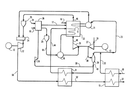
Figuxe 1 18 a ~chematic diagra~ o~ a ~a8i6 ~olid
- Puel ~vaporatlv~ regener~tiv~ ga~ turbln0 ~y8t~
P~igure 2 i~ a ~c:hemat1c dlagraDI of a solid ~uel
S eYaporative-regen~rativa ga~ turbine ~y~te~ with reheat.
Figure 3 i8 ~ h~mz~tic dias~ram o~ a solld fuel
evaporative-regerlerativ~ ga~ turbine ~ystem with re~at, a
~ol?ping combu8tor and a carboJaizer.
Referri~g to the dra~ings, wherein lik~ numeral~ repre~ent
like elements, there is lllustrated in Figure 1 a basic 601id fuel
ev~p~ra~ive-regenerative gas turbine syste~. An oxygen-bearing gas 26,
such as ambi~nt air, enter~ a compressor 27 which may be of the axial
flo~ type and i8 compressed. According to ~n important aspect of the
invention, the compressed ga~ 38 then flows through a spray evaporator
29 where it undergoes ~vaporative coolin~. The spray evaporator
comprises a chamber, water from a high pres~ure supply 30 is sprayed
into the chamb~r and mixes with the compressed gas flowlng through the
chamber. As a result of compreg~ion the gQ8 iS hot, he~ce the wat~r
spray is vaporized .~n the gas. The water latent he~t of vaporization
slgnif~c~ntly lo~ers the temper~ture o~ the gas while the molstur~
carri~d by the g~s incresses it~ m~s flo~.
2 S In ~ccordanca with another important a~pect o~ the
invention~ the cool moisture-laden coDlpre~sed gaQ 40
prodlucad by the spray evaporator th~n flows through a
regeneratGr 31. Expanded vltiated gas 42 produced by a
turbine 14 also flows through the regener~tor. The
3 0 regenerator i8 a cha~nber in which barriers are di~posed
whlch creat~ two group~ Or pa~sageway~3. Th~ cool gas fro~n
the spray evaporator ~lc)w8 through OrlQ group of passageways
a!lnd the gas ~rom th~ tur~ine ~lows thrc)ugh the second group.
Th~ barrier~ prevent mixing o~ the two ga3es a~ they ~low
throu~h the regenera~or but allow the transfer o~ heat
be~ween the ~wo gase . S ince, a~ a re~ult o~ the
~vaE~orativ2 cooling in the spray evapora~or, the temperature
of the compressed ~a~ ~ro~ th~ ~pr2l~f evaporator i8
.
.~ , . ~ , . . .
7 ~3~9~3 54,572
significantly lower than that of ~he expanded vitiated gas
from the turbine, there is considerable heat transfer
between the two gases and an attendant significant rise in
the temperature of the co~pressed gas. The heated
compressed gas 44 produced by the regenerator then flows to
a PFBC 33~ The PFBC consumes a solid fual 10, such as coal,
and a sulfur sorbent 34. The PFBC comprises a combustion
chamber in which the solid fuel is maintained in a
pressurized fluidized bed to promote combustion. The heated
compressed gas 44 fluidizes the bed and supplies the oxygen
necessary for combustion of the solid fuel in the
pressurized fluidized bed (hereinafter PFB); the temperature
of the gas is raised by the tran~fer of heat released by the
burning fuel. The amount of solid fuel-burned in the PFBC
depends on the desired gas temperature.
The hot gas 46 thus produced by the PFBC, now
vitiated by the combustion products, flows through a turbine
wherein the hot vitiated gas expands, thereby producing
power in the rotating shaft of the turbine. Prior to
entering the turbine the hot gas from the PFB flows through
a cy~lone separator 25, wherein much of the particulate
matter entrained in the air is removed, thu~ minimizing
erosion and fouling in the turbine. The expanded vitiated
gas 42 produced by the turbine 14 flows through the
regenerator 31 a~ explained previously, transferring to the
cool compressed gas much of its sensible heat remaining
after expansion. The cooled vitiated gas produced by the
regenerator is then discharged to atmosphere through vent
32.
Although a portion of the power produced by the
turbine is used to drive the compress~r 27, a significant
excess o~ rotating shaft power is produced and may be used
ta generate electrical power by driving the ~haft of a
dynamoelectric machine 13.
The thermodynamic efficiency of the system thus
described can be de~ined as the ra~io of the net power ~the
portion of the power produced by the turbine available for
work outsi~e the o~cle, i.e. a~ter3*he power absorbed by the
~ 13~9~ 54,572
compressor is accounted ~or) to the thermal en~rgy available
in the fuel consumed (the heat that would be generated by
complate combustion o the quantity of fuel consumed). Thus
the thermodynamic efficiency is optimized by minimizing the
fuel consumed and maximizing the net power produced. An
inherent aspect of the gas turbine cycle is that the
temperature of the gas after expansion in the turbine,
although reduced as a result of the expansion, is still
relativ~ly high. Thus, if the gas from the turbine is
merely vented to atmosphere, no power will be produced by
the portion of the thermal energy released by the fuel in
order to raise the temperatur~ of the gas entering the
combustor to its temperature aPter expansio~ in ~he turbine,
causing a reduction in the e~ficiency of the æy~tem.
In the solid fuel system described, the invention
disclosed solves the problem discussed above by utilizing
the regenerator 31 to recover much of the thermal energy
still available in the expanded gas from the turbine 14.
The sensible heat thus rscovered is utilized in the system
by transferring it to the compressed gas from the compressor
prior to its entry into the PFBC thus reducin~ the fuel
consumption required to achieve the desired gas temperature
entering the turbine.
Another inherent aspect of the gas turbine cycle
is that the power produced by the turbine is propoxtional to
the mass flow of the gas expanded through it. Hence
increasin~ the mass flow increases the power produced.
However, ~ince the power absorbed by the compressor in
compressing the gas and the fuel consumed in the combustor
in heating the gas is also proportional to the mass flow,
increases in mass flow do not improve e~ficiency. The
invention disclosed circu~ents this limitation and improves
the efficiency of the solid ~uel system described by more
than that achieved by regeneration alone b~ combining
regeneration with incr~ased mass flow ~rom evaporativ~
cooling. Since, according to the invention disclosed, the
mass ~low of the gas is increas~d by vaporization of water
into the g~s afte~compression, the power absorbed by the
9 ~ 3 ~ 3 54,572
compressor is not increased, thus freeing all o~ the power
produced for use outside of the system. Further, while
merely vaporizing water in this manner would increase the
powex produced in the turbine, the cooling effect of the
S vaporization would increase the fuel consumption required in
the combustor to achieve the desired temperature of the gas
entering the turbine. However, since the amount o~ heat
transferred in the regenerator is proportional to the
temperature difference between the compressed and expanded
gases, the cooling of the compressed gas as a result o~
vaporization increases this heat transfer, thus of~setting
the required increase in fuel consumption. Consequently,
the invention disclosed substantially improves efficiency of
the solid fuel system described by increasing the net power
produced in the tur~ine with only a proportionately smaller
increase in solid fuel burned in the PFBC. This improvement
in efficiency can be obtained at lower cost and with less
complexity than by the use o~ the steam bottoming system as
indicated by the prior a.rt.
The benefits of the evaporative~regenerative
scheme in a solid fuel system according to the invention
disclosed is not limited to the basic ~olid fuel system
illustrated in Figure 1 and discussed above. ~ccordingly
Figure 2 illustrates a solid fuel ~vaporative-regenerative
gas turbine system with reheat. In this system the turbine
has been split into high and low pressure sections 35 and 12
respectively (alternatively, separate high and low pressure
turbines may be used), and the heated compressed gas 44
produced by the regenerator 31 flows through an indirect
heat exchanger 11 disposed in the combustion chamber of the
PFBC 33 prior to entering the high pressure section of the
turbine 35. In the indirect heat exchangPr the te~perature
o~ the gas is raised by tran~ferring heat released by the
burning solid fuel as in the basic system, except that there
is no direct contact betwe~n the gas and solid ~uel. Hence
compressor surge due to ~ouling of the high pressure section
of the turbine is avoided as prsviously discussed. The hot
compressed ~as frd~ the indirect heat exchanger undergoes
~3~5~3
54,572
partial expansion in the high pr~ssure section of the
turbine 35. The partially expanded gas 48 produced by the
high pressure section of the turbine then en~ers the
pressurized fluidized bed portion of the PFBC ~3, this time
mixing with and fluidizing ths solid fuel, supplying ths
oxygen ~or combustion of the ~uel and absorbing heat as in
the basic system previously discussed~ This heating of the
gas between the high and low pxessure sections o~ the
turbine is referred to as reheating. The gas ~6 produced by
the PFBC, now vitiated by the products of combustion,
completes its expansion process in the low pressure section
of the turbine 12. The expanded vitiated gas 50 produced by
the low pressure section o~ the turbine then flows through
the regenerator 31 and the cooled vitiated gas is vented to
atmosphere as before. In this system power is produced by
both the high and low pressure sections o~ the turbine.
Since this system allows the use of a higher compression
ratio in the compressor 27 becau-qe of the elimination of the
fouling induced surge problem of the system in the Figure 1,
the temperature of the ga~ fro~ the compressor will be
: hotter and approach that of the gas from the turbine. Thus,
": the spray evaporator becomes increasingly important as a
means for recovery oP exhaust heat.
The power produced by a turbine is proportional to
the temperature drop across the turbine, as well as the mass
flow through it. Hence, the higher the temperature of the
gas entering the turbi~e the greater the power produced.
However, as pr~viously discussed, the firing of the PFBC is
limited to 1600 F to optimize sulfur capture and avoid
carryover of harmful alkali ~apors into the turbine. This
limitation may be overcome by the use of a topping combustor
burning a non-solid (gaseous or liquid) ~uel. As in the
previously discussed system the gas from the regenerator 31
is heated in an indirec~ heat ex~hanyer 11, however, after
the indirect heating the temperature of the hot compressed
gas is further increased in a topping co~bustor, wherein the
non-solid fuel is mixed and burned in the hot compressed
gas. The ~as supp~ios the oxygen necessary for combustion
~3~ 5~3~
11 54,572
and absorbs heat released by the burning non-~olid fu~l.
After discharging from the topping combustor, the gas
partially expands in the high pressure sec~ion of ~he
turbine a~d then en~ers the PFB as in the system pr~viously
S discussed. Since raising the temperature of the gas
entering the turbine raises the temperature of the gas
exhausting from the turbine as well, the need to recover
exhaust heat in the regenerator to optimize efficiency
becomes increasingly important when a topping combus~or is
used.
Figure 3 illustrates the use of a topping
combustor 16, as well a~ other aspects of the integration of
the evaporati~e~regeneratiYe scheme into an advanced solid
fuel gas turbine system utilizing coal. Tha coal is
converted to a carbonaceous char and a hydrocarbon-based
gas, typically low BTU gas, in a carboniæer 36 using a
pyrolysis process. The carbonaceous char 17 is burned in
the PFBC 33 and, after cleanup in a cyclone separator 25,
the hydrocarbon based gas 18 is ~urned in the topping
combustor 16, allowing the maximum utilization of coal. In
addition to coal 10 and sulfur sorbent 34, the carbonizer 36
requires a supply o~ high pressure oxygen. Such oxygen is
obtained by a bleed 20 which directs a portion of th~ gas
discharged from the spray evaporator 29 to a boost
compressor 19 and thence to the carbonizer. Since it is
more efficient to use the energy available in the coal in a
topping combustor than.in the PFBC~ it is desirable to
maximize the ratio of gas to char production in the
carbonizer. Thus, in accordance with another aspect o~ the
invention in a carbonizing/topping combustor cycle, the
moisture in the high pre~sure air supplied to the carbonizer
as a result of the spray evaporator will incrPase the ratio
of gas to char produced by the carbonizer, thus further
improving the efficiency of such a system.
A steam generator 21 is required, in addition to
the indirect heat exchanger 11, to control the temperature
of the PFBC. The ~team generator is supplied with feed
water 23 a~d its ~at transfer surfaces are disposed inside
~ 3 ~
12 54,572
the PFBC, whereby they absorb heat to convert the ~eed water
to steam. Under the prior art the steam generated in this
manner was combined with that generated in the HRSG and
utilized in a steam tur~ine. Since, according to the
invention, the HRSG/steam turbine scheme is no longer
required, Figure 3 discloses the incorporation of a steam
injection system 24 into the system. The steam injection
system mixes the steam generated in the steam generator with
the gas entering the low pressure section of the turbine
thereby producing additional power in the turbine.
Alternatively, the steam could be utilized in the hiyh
pressure section of the turbine by either injecting it into
the gas to produce additional power, or distributing it, in
a steam cooling system, to the portions of the high pressure
1~ turbine exposed to the gas to cool such portions o~ the
turhine. While the use of the regenerator removes much of
the excess sensible heat from the turbine exhau~t gas, a
portion still remains. Hence Figure 3 discloses another
aspect of the invention wherein water 30 and the cooled
vitiated gas 52 from the regenerator flow through a
gas~water heater 15, wherein the gas transfers a portion of
its sensible heat to the water. The gas from the gas/water
heater i5 then discharged to atmosphere through vent 32. A
portion o~ the heated water 22 then supplies the spray
evaporator 29 and the remainder 23 supplies feed water to
the steam generator 21, thereby returning the heat to the
sy~tem.