Note: Descriptions are shown in the official language in which they were submitted.
~ l - 13~02
Improved rapi~ fastener of the bayonet type
The mechanical assembly of t~o parts or elements may be
achieved in many various ways. One of the simplest ways
which takes up the smallest amount of space is the use of a
coupling of the bayonet type comprising on one of the ele-
ments a projecting pin, and on the end of the other element
a socket having a slot for receiving and locking the pin.
- ~ Couplings of this type are well known and employed in
many fields. However, they are reserved for the connection
of elements intended to remain stationary since they can only
ensure with difficulty the reliable transmission of a
torque, above all if the latter is large.
For the purpose of ensuring an assembly of complete relia-
bility,the most currently employed means are for example :
collars, screw-and-nut systems or other systems. Their draw-
backs are that they requir~e precise moving operations and the
application of well-determined clamping forces which create
'
possible errors~in the positioning.
An object of the present invention is to overcome these
drawbacks and to provide a rapld fastener which, while having
the advantages of a coupling of the bayonet type, ensures a
connection with no axial or angular cl;earance permitting, on
- one hand, the transmission of even large torques and, on the
other hand, the establishmént of the connection by a single
shiftlng and being capable of being disassembled a~ any moment.
The invention indeed provides a rapid fastener of the
bayonet type comprising, on one hand, a female socket having
' ~ .
~160~2
at least one helical slot and, on the other hand, a male
stem carrying at least one laterally projecting pin capable
of being disposed in the slot of the socket, and guiding and
locking means carried by the socket and elastically biasing
the pin into the bottom of the helical slot and locking the
pin in this position.
The object of the inven-tion is also to provide a
rapid fastener of the bayonet type for connection of two
elements, comprising a socXe-t terminating the first element,
a stem terminating the second element, the socket having an
open end for receiving a stem, a laterally proiecting pin on
the outer surface of said stem, a slot in the socket, said
slot having an open entrance end for -the entrance of said
projecting pin, guiding and locking means comprising a ring
axially slidable along the socket but rotating with said
socket, spring means for biasing said ring toward the open
end of said socket, a longitudinal slot formed in said ring
and having an open end toward the open end of the socket,
and two lateral walls progressively diverging toward said
open end of the longitudinal slot; said longitudinal slot
: open end being laterally offset relative to said open
entrace end of the socket slot and having an end edge which
partly closes said entrance end of the socket slot and which
is urged back by the pin as the stem penetrates in said~ 25 socket, said socket slot having an helical shape which
causes helical relative motion of said penetrating stem and
said socket and guides the pin to the entrance end of the
longitudinal slot so that the end edge of said longitudinal
slot is released and the rin~ is biased to a locking
position in which the pin is trapped by edges of the two
slots.
. .
- 2a -
~316002
According to a preferred embodiment, the guiding and
locking means cbmprise a ring mounted to be axially slidable
along the socket but biased toward the open end of the sock- -
$ ket by a spring, said ring comprising in facing relation toeach o the helical slots of the socket an open longitudinal
slot which is laterally offset relative to the entrance of
: the helical slot.
With this arrangmeent, a mere axial force exerted on ei-
ther of the elements to be interconnected constrains each of
the driving pins to urge back the slidable ring so as to enter
the helical slot and then, under the combined action of the
edges o the two slots, to efect the angular displacement
required for the locking thereof and the return of the ring
~ to the locking position. The two ele~ents are then assembled .
: in a sure manner and with no.angular clear.ance and are capa-
~; ~le of transmitting torques in either direction whatever be
the magnitude thereo~.
The following description o an embodiment given by way
of a non-limitative example and shown in the accompanying
drawings~ will being~out ~the advantages and ~eatures of the
invention.
~ ' :
. _
.
~ 3 ~ 2
-- 3 --
In the drawings : .
F1g. l is an exploded perspective view of a rapid faste-
ner according to the invention ;
Fig. 2 is an elevational view of the assembled rapid
fastener ,
Fig. 3 is an elevational view of a modification of the
assembled rapid fastener.
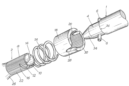
; The rapid fastener according to the invention lS adapted
to interconnect two elements, and in particular two coa~ial
shafts l and 2, the shaft l of which has at its end an elon-
gated stem 4 of substantially cylindrical shape which carries
at least one driving pin 6 and preferably two pins, as shown
in Fig~ l. The element 2 terminates in a hollow, also cylin-
drical, socket 8 which is open at its entrance end lO and in
the wall of which are provided two slots 12 each capable of
~eceiving one of the pins 6.
Each of the slots 12 has a curved shape, i.e. lt inclu-
des, following on a substantially axial entrance portion 14,
:: a substantially hel1cal portion 16.
~ 20 Slidably mounted on the socket 8 is a ring l~ which is
; connected to rotate with the socket by any suitable means,
such as flat faces, a polygonai shape or,as shown, longitu-
dinal splines 20 provided on its inner surface and cooperat-
.
ng with complementary splines 22 on the outer surface of the
socket 8. A coil spring 24 is also mounted around the socket
8. It bears, on one hand, against -the edge of the slidable
ring 18, and,on the other hand~agsinst an outer shoulder~or a
. ,
.
~3~L6~2
-- 4
projection 26 on the element 2 so that it tends to bias the
ring 18 outwardly, i.e. in the direction toward the open
end.10 of the socket 8.
The ring 18 further comprises two slots 28 extending
generally longitudinally and oFen at the end of the ring which
i5 remo~e from the spring 24. Each of the slots 28 has suf-
ficient width to permit the entry of the pin 6 of the element
l. Preferably, these slots 28 have a divergent shape, their
width increasing progressively in the direction toward their
open end (Fig. l.).
As is shown more particularly in Fig. 2, each of the
slots 28 is disposed on top of one of the slots 12 of the
socket 8, but is laterally offset relative to the entrance 14
of the slot 12 so that the end edge 30 of the'ring 18 partly
closes this entrace of the slot 12.
I One or m~ore lugs 32 formed for example by a press opera-
;~ tlon or by a formlng-over operation on the material of the
socket 8, after the mounting of the ring 18, retain this ring
on the socket. At rest, i.e. before the assembly of the rapid
~20 fastener, the ring 18 is thus biased by the spring 24 against
the lugs 32 in a well-determined angular position.
.
When it is desired to achieve the connection between the
elements l and 2, it is sufflcient to introduce the elong.a-
ted stem 4'inside the socket 8 in placing each of the pins 6
.
: ~ '25 in front of the entran.ce 14 of one of the slots.l.~.. An axial.
~ force on either of the elements l and 2'then enables the pin
,
6 to urge back the edge 30 of the ring 18 against the action
1316~2
of the spring 24 and thus to enter the slot 12. However,
owing to the force exerted by the spring 24 and the inclina-
tion of the lower edge of the portion16 of the slot 12, the pin 6
is progressively laterally urged back by -the edge of the
slot 28 so that, as it axially advances in the socket, it is
angularly displaced relative to the entrance of the slot 12
and approaches the inner end of the latter. It then slides
along the oppopsed edges of the two slots and thereby enables
the rlng 18 to progressivley resume its initial position.
At this moment, as shown clearly in Fig. 2, the pin 6 is
trapped between edges of the slots 12 and 28 so that at any
moment the return movement thereof is precluded.
Preferably, an outer shoulder 36 is formed at the junc-
tion between the element 1 proper and the stem 4 and the
abutment of this shoulder against the edge 10 of the socket
8 corresponds to the locking positlon, which facilitates the
positioning of the fastener.
The element.s 1 and 2 -are then clbsely locked together.
Thmlr axial displacement is precluded by the contact of the
pin 6 with the edges of the slot 12 while their relatlve
displacement ln rotation is precluded by the contact of the
pin 6 with the edges of the two slots 12 and 28. The inter-
locklng of the elements 1 and 2 is without clearance, as the
.
angular and/or axlal clearances are automaticàlly taken up
by the compression spring, irrespective of the manufacturing
tolerances and the wear of the assembly.
Such~a connection is achieved by a simple axial force,
.
131~B2
-- 6 --
the angular displacement occurring automatically under the
effect of the exerted pressure. Furthermore, it does not re-
quire any precise handling, since a slight original offset
of the pin 6 relative to the slot 12 is corrected automatical-
ly by-a relative angular displacement of the two elements,
while a larger of f set preventing the connection is immediately
detected, the two elements remaining independent. Thus, the
slightest torque exerted on one of the elements confirms the
locking or indicates its absence, The connection is therefore
extremely reliable and safe.
This connection may also be very easily dismantled by
urging the ring 18 against the action of the spring 24, which
instantaneously releases the pins 6 and the element 1.
The rapid fastener is consequently most particularly
adapted to the connection of elements which are difficult of
access, or even to connections achieved automatically or
remote controlled, whether the elements to be connected are
solid or hollow, the stem 4 being if desired hollow.
Preferably, the positioning of the fastener is facili-
ZO tated by the presence at the end of the stem 4 of a conicalportion 34 which facllitates the centering and the entry in
the socket 8. ~
It will be understood that the stem 4 and the inner sur-
face of the socket 8 preferably have a cylindrical shape with
: , . . ~
a circular base, but they may have any o~her suita~l~e profile.
.
They may in particular have complementary prismatic profiles
defining therebetween a sufficient clearance to permit the
,
13~6~2
-- 7 --
locking but ensuring a positive driving in the event of a
breakage of the driving pin. Furthermore, the driving pins
may have a cylindrical shape with a circular base, as shown,
or have suitable slopes corresponding to the bearing against
the edges of the slots so as to increase the contact surfaces.
It will be clearly apparent that the number of driving
pins, helical slots and locking slots may vary in accordance
with the utili~ation and the magnitude of the forces to be
transmitted.
In some cases, moreover, it is advantageous to employ as
a coil spring 24, a spring formed by a flat strip wound into
a helix instead of a wire. The spring then forms around the
socket a protective sheath against impurities or other exte-
rior attack.
; 15 A still greater protection against impurities may be
obtained by constructing the fastener according to the modi-
fication shown in Fig. 3. Indeed, in ~his case, the gu1ding
and locking ring 38 is slidably mounted inside the socket 40
of the element 2. It is connected to rotate with the socket
by splines 20, 22 or by any other suitable profile. A spring
24 is also disposed inside the socket between the inner end
42 of the inner bore of the socket and the ring 38. Radial
lugs 44 formed at the open end of the socket 40 radially pro-
ject inside the socket to prevent the ring 38 from moving out
.
2~ of the soc~et.
The ring 38 includes, as the ring 18, divergent longitu-
dlnal slots 28 which are laterally offset relative to the
~ 3 ~ 2
entrance 14 of each of the slots 12 of the sccket 40.
The stem 4 o~ the element 1 has, in this case, a profile
and dimensions which are complementary to those of the ring
38 in which it must penetrate.
The assembly is achieved in the same way as with the
fastener shown in Figs. 1 and 2. By inserting the stem 4 in
the ring 38, the pins 6 are made to urge this ring back so as
to enter the slots 12 and then the edges of the slots 28 of
the ring urge back these pins 6 to the inner end of the slots
12 and lock them in this position.
As shown in Fig. 3, all the elements of the fastener are
then protected and isolated from the exterior by the socket
which abuts against the shoulder 36 of the element 1. They
can be neither attacked nor damaged by exterior action.
:
.
: . '
:
, '
.