Note: Descriptions are shown in the official language in which they were submitted.
1 3 ~
TRANSVERSE CONNECTOR FOR
SPINAL COLUMN CORRECTIVE DEVICES
Back~round of the Invention
Technical Field
The present invention relates to a transverse connector
for interconnecting spinal column corrective devices and,
in particular, to a transverse connector which enables the
spac1ng of the corrective devices at different distances
~ ~ apart and at different orientations.
::' :
;~ Description of the Prior Art
:
Transverse connectors for interconnecting spinal column
corrective devices are known. U.S. Patent No. 3,693,616
di~scloses a pair of bars for correcting curves of the
spinal aolumn. Each of the bars have a plur~ality of
openings extending therethrough. The bars are located on
opposite sides of the spinous processes and are connected
to the splnal column by a lacing wire extending through the
openings around portions of the spinal column. Spacers are
:
-2- ~3~
loca~ed between the bars and each spacer has axial end
portions connectecl with the bars to block relative movement
of the bars.
Transverse connectors for interconnecting a pair of rods
which are connectable with the spinal column are also known.
One such transverse connector, referred to as a "Transverse
Fixator", includes a pair of clamp halves. A pair of spaced
apart recesses are located in each of the clamp halves at a
fixed distance apart. The clamp halves cooperate so facing
recesses receive a portion of one of the rods therebetween.
A fastener is inserted through an opening in one clamp half
and is tightened in a threaded opening in the other clamp
half. The clamp halves, thus, grip around respective
portions of the rods and block relative movement of the
.
rods.
Another transverse connector for rods, available from
Stuart in Greensburg, Pennsylvania, includes an elongate
threaded rod with a pair of clamps~ A clamp half of one of
the clamps is fixed to an end of the threaded rod. The
other clamp half of the one clamp is movable along the
::
~ threaded rod toward the fixed clamp half to grip around a
.: ~
portion of a corrective rod. Another one of the clamps
grips around a portion of the another corrective rod and is
movable along the threaded rod to allow the corrective rods
~ to be spaced apart at different distances.
s Another such transverse connector for rods, availabie
from Danek in Memphis, Tennessee, includes a plate having a
-3~
pair of rectangular openings. The plate also has a pair of
parallel extending recesses located at a fixed distance
apart for receiving a portion oE respective rods. An
eyebolt is received on a portion of a rod and is received
in the rectangular opening in the plate. When a nut is
tightened on the eyebolt, the rods are drawn into the
recesses to clamp the rods and block relative movement of
the rods.
~`
summarY of the Invention
~ he present invention is directed to a transverse
connector for interconnecting a pair of members, such as
spine plates or rods, which are connectable with vertebrae
of a spinal column. Each spine plate has a plurality of
openings for receiving a fastener to connect the spine
plate to a vertebra. The transverse connector comprises a
member extendable between the spine plates in a direction
transverse to the axes of the openings in the spine plates.
First attaching means connects a first portion of the
member with one of the spine plates. Second attaching
means connects a second portion of the member with the
other of the spine plates. The locations of the first and
second attaching means along the member may be changed to
enable the member to interconnect the spine plates which
can be spaced different distances apart.
In one embodiment of the present invention, the member
comprises an elongate plate with an elongate opening. Each
4- ~ 3 ~
of the Eirst and second attaching means comprises a fas~ener
which attaches the elongate plate to a spine plate and
includes a portion extendable -through the elongate opening
in the elongate plate and through an opening in ~he spine
plate. The fastener is movable along the length of the
elongate opening in the elongate plate to change the
location at which the fastener attaches the spine plate to
the elongate plate.
- In another embodiment, the member comprises an elongate
rod having threaded axial end portions. Each of the first
and second a-ttaching means comprises a clamp connectable
with a respective threaded end portion of the rod. Each
clamp includes a first portion receivable in an opening in
one of the spine plates. A second portion of the clamp
cooperates with the first portion to apply a clamping force
to a portion of the spine plate. Each of the clamps are
movable along the~rod to change the location at which the
clamps attach the spine plates to the rod.
In yet another embodiment, the member comprlses an
elongate rod having end portions which are threaded. Each
of the first and second attaching means comprises a clamp.
Each clamp includes a portion with an internally threaded
opening for threaded engagement with one of the threaded
end portions of the rod. Each portion of each clamp is
movable axially along the rod in response to rotation of
the rod about its longitudinal central axis.
1 3 ~
In still another embodiment of the present invention,
the transverse connector interconnects a pair oE corrective
rods each of which are connectable with vertebrae of a
spinal column. The transverse connector comprises an
elongate rod extendable between the corrective rods in a
direction transverse to khe longitudinal central axes of
the corrective rods. The elongate rod has end portions
which are threaded in opposite directions. Each of a pair
of clamps is connectable with a respec~ive threaded end
portion of the elongate rod. Each clamp includes a first
portion and a second portion cooperating with the first
portion to apply a clamping force to a portion of one of
the corrective rods. The first portions are moved
relatively toward one another in response to rotation of
the rod about its longitudinal central axis in a first
direction. The first portions are moved relatively away
from one another in response to rOtatiQn of the rod about
its longitudinal central axis in a second direction
opposite the first direction.
In yet another embodiment of the present invention, an
articulated transverse connector is used to interconnect
skewed spine rods. The articulated transverse connector
includes first and second connecting members, each of which
have an axial end portion and a longitudinal central axis.
Clamp means attaches the connecting members to the spine
rods. The axial end portions of the connecting members are
connected by a join-t capable of articulation so the
- ~ 3~6~
connecting members may be positioned with their longitudinal
central axes skewed relative to one another.
Brief Description o the Drawings
Further features of the present invention will become
apparent to those skilled in the art to which the present
invention relates from reading the following specification
with reference to the accompanying drawings, in which:
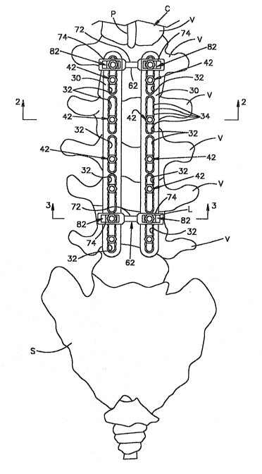
Fig. 1 is a view of one embodiment of the transverse
connector of the present invention interconnecting a pair
of spine plates which are connected to a spinal column;
Fig. 2 is an enlarged cross sectional view of the spine
plates in Fig. 1 connected to a vertebra, taken
approximately along line 2-2 in Fig. l;
Fig. 3 is an enlarged cross sectional view of the
transverse connector in Fig. 1 interconnecting the spine
plates, taken approximately along line 3-3 in Fig. l;
Fig. 3a is an enlarged view of a cross bracket in Fig.
3;
Figs. 3b and 3c are enlarged view of a fastener in Fig.
3;
Figs. 4, 6, 10, 13, 15 and 17 are views similar ~o Fig.
1 illustrating other embodiments of the transverse
connector of the present invention;
Fig. 5 is an enlarged cross sectional view o~ the
transverse connector in Fig. 4 interconnecting the spine
plates, taken approximately along line 5-5 in Fig. 4
:.
-7- ~3~
Fig. 7 is an enlarged cross sectional view of the
transverse connector in Fig. 6 interconnecting the spine
platesl taken approximately along line 7-7 in Fig~ 6;
Fig. 8 is an enlarged cross sectional view of a portion
of one of the clamps illustrated in Fig. 7;
Fig. 9 is an enlarged perspective view of another
portion of one of the clamps illustrated in Fig. 7;
Fig. 11 is an enlarged cross sectional view of rods in
Fig. 10 connected to a vertebra, taken approximately along
line 11-11 in Fig. 10;
Fig. 12 is an enlarged cross sectional view of the
transverse connector in Fig. 10 interconnecting rods, taken
approximately alony line 12-12 in Fig. 10;
FigO 14 is an enlarged cross sectional view of the
transverse connector in Fig. 13, taken approximately along
line 14-1~ in Fig. 13;
Eig. 16 is an enlarged cross sectional view of the
transverse connector in Fig. 15, taken approximately alone
line 16-16 in Fig. 15; and
Fig. 18 is an enlarged cross sectional view of the
; transverse connector in Fig. 17, taken approximately along
line 18-18 in Fig. 17.
; Description of Spe iEic Preferred Embodiments
One embodiment of the present invention is illustrated
in FigO lu A portion of a spinal column C (Fig. 1)
-8- ~3~
includes a plurality of vertebrae V and a sacrum S. A pair
of spine plates 30 are connected to some of the vertebrae V
to maintain the relative positions of the vertebrae. The
spinous process P of each vertebra may be removed if
required. It will be apparent that the spine plates 30 may
be located anywhere along the spinal colu~n C, and the
location of the spine plates ill.ustrated in Fig. 1 is for
example purposes.
Each of the spine plates 30 is elongate and has a
sufficient length to span several vertebrae V. A plurality
of elongate openings 32 extend through each spine plate
30. The openings 32 receive a fastener 42, as illustrated
in Fig. 2, to connect each of the spine plates to a pedicle
D of the vertebra V. A plurality of frustoconical or semi-
spherical shaped recesses 34 are spaced along the length of
each opening 32.
Each fastener 42 includes a bone screw 44 (Fig. 2)
having a threaded portion 50 threaded into a cancellous
portion of the vertebra V. A shoulder 46 on the screw 44
spaces the spine plate 30 away from vertebra V. The
fastener 42 also includes a nut 52 which is threaded onto
another threaded portion 54 of the screw 44 which extends
through the opening 32. The nut 52 is received in one of
the recesses 34 spaced along the opening 32. The nut 52
has an external portion 56~for engaging the surface of a
recess 34 to block movement of the spine plate 30 relative
to the screw 44.
: _9_
~ 3 1L ~
A pair of transverse connectors 62 (Figs. 1 and 3)
interconnect the spine plates 30. The transverse
connectors 62 block relative movement of the spine plates
30 so the vertebrae V connected to the spine plates are
maintained in their desired relative positions and do not
pivot relative to an anterior-posterior axis or a
longitudinal central axis A of the spinal column C. The
transverse connectors 62 are located near axially opposite
end portions of the spine plates 30 so the resulting
structure forms a parallelogram. It will be apparent that
the transverse connectors 62 may be located anywhere along
the elongate openings 32 of the spine plates 30.
Each transverse connector 62 (Fig. 3) includes a pair
of elongate plate portions 74 to connect together the spine
plates 30. The plate portions 74 extend transversely to
the axes X of the openings 32 in the spine pl~ates 30 and
are connected by a bendable rod portion 72. Each plate
portion 74 includes a pair of elongate openings which
extend in a direction substantially parallel to and along
the longitudinal central axis L of the connector 62. The
rod portion 72 may be bent to allow the plate portions 74
to be located flat against a respective spine plate 30 to
accommodate non-coplanar and/or non-parallel spine plates
30.
A fastener 82 (Fig. 3b1 extends through a respective
opening to connect one of the plate portions 74 with one of
the spine plates 30. The fastener 82 includes a screw
-lo- ~3~$~
84 having a threaded portion 86 extending through a cross
bracket 90 (Fig. 3a) located in the opening 32 in the spine
plate 30 and through the opening in the plate portion 74.
The screw 84 also includes a square head 88 (Fig. 3c) which
fits in the opening [best seen in Fig. 3) in a surface of
the spine plate 30. The square head 88 interacts with the
opening to block rotation Qf the screw 84 about its
longitudinal central axis during tightening of a nut 96
onto the screw. The cross bracket 90 blocks the transverse
connector 62 from pivoting about the axis X relative to the
spine plate 30.
The nut 96 includes an internally threaded opening for
threaded engagement with the threaded portion 86 of the
screw 84. The nut 96 also includes a hex head for
receiving a tool, such as a wrench, to tighten the nat onto
the screw 84. When the nut 96 is sufficiently tightened
against the plate portion 74, a clamping force is applied
between the plate portion 74 and the spine plate 30 to
block relative movement therebetween.
The spine plates 30 may be spaced different distances
apart to accommodate different size vertebrae V or location
requirements determined by the surgeon attaching the spine
plates. In order to permit one design of the transverse
connector 62 to be used with the spine plates 30 spaced
apart at different distances, the fastener ~2 may be
located at different positions along the opening in the
~ 3 ~
plate portion 74. For example, if the spine plates 30 were
located at different distances apart from the position
illustrated in Fig. 3, the threaded portion 86 of each
fastener 82 could be relocated along the openings in the
plate portion 74. ~hus~ an assortment of different length
transverse connectors or transverse connectors having
different distances between openings for receiving the
fasteners 82 is unnecessary.
Another embodiment of the transverse connector of the
present invention is illustrated in Figs. 4 and 5. Spine
plates 110 are connected to vertebrae V of the spinal column
C. Each spine plate 110 has a plurality of elongate
openings 112 which receive fasteners 114 to connect the
spine plates to the vertebrae V, as described above. A pair
of transverse connectors 122 interconnect the spine plates
110 to block relative movement between the spine plates.
Each transverse connector 122 (Fig. 5) includes an
elongate threaded rod 132 extending between the spine
plates 110 in a direction transversely to the axes X of the
openings 112 in the spine plates 110. A pair of axially
spaced clamps 142 attach the rod 132 to the spine plates
110. The threaded rod 132 may be bent if necessary to
accommodate non-coplanar and/or non-parallel spine plates
110 .
Each clamp 142 includes a pair of similar clamp halves
144 which clamp around a portion of one of the spine plates
110. A pair of nuts 146 are located on opposite sides of
the clamp 142. The clamp halves 144 are pressed together
to clamp the spine plate 110 when the nuts 146 are rotated
on the rod 132 in a direction toward one another.
Each clamp half 144 includes a connector portion 152.
An opening 154 extends through the connector portion 152
and receives a portion of the rod 132. The inner diameter
of the opening 154 lS sized larger than the crest diameter
of the thread on the rod 132. The clearance created allows
the clamp half 144 to rest squarely on the plate portion 74
o the spine plate 30.
Each clamp half 144 also includes a body portion 162
extending from the connector portion 152. The body portion
162 includes a surface defining a rectangular recess 164.
The body portion 162 of one clamp half 144a extends into
the opening 112 in the spine plate 110, The other clamp
half 144b cooperates with the clamp half 144a received in
the opening, to apply a clamping force to a rectangular
portion 172 of the spine plate 110 received between the
clamp halves. The rectangular recesses 164 in clamp halves
144a, 144b define a rectangular opening which is slightly
larger than the rectangular portion 172 of the spine
plate. Thus, little or no relative rotation between the
spine plate 110 and clamp 142 occurs in a plane containing
the longitudinal central axis L of the rod 132 and which
extends substantially perpendicular to the spine plate 110.
:
-13- 1316~5~
A spacer portion 182 extends from the connector portion
152 of each clamp half 144 on an opposite side of the
opening 154 than the body portion 162. When the clamp
halves 144a, 144b are moved toward one another, the spacer
portions 182 on each clamp half engage one another. As the
clamp halves 144a, 144b are presssed together by the nuts
146 being tightened on the rod 132, the body portions 162
pivot toward one another about the spacer portions 182, so
the clamping force is transmitted to the body portions 162
to grip the portion 172 of the spine plate 110.
Another embodiment of the transverse connector of the
present invention is illustrated in Figs. 6 and 7. The
transverse connector 202 (Figs. 6 and 7) interconnects a
pair of spine plates 204. The transverse connector 202 may
be used when the spine plates 204 are skewed relative to
one another, as illustrated in Fig. 7. Each spine plate
204 has a plurality of openings 206 for receiving a
fastener 208 to connect the spine plate to a vertebra V, as
described above.
The transverse connector 202 (Fig. 7) includes an
elongate member 210 having an axial end portion 212 with a
righthand thread and an axial end portion 214 with a
lefthand thread. A drive portion 216 is located
intermediate the threaded axial end portions 212, 214. The
drive portion 216 receives a suitable tool (not shown) for
applying a torque to the member 210 and rotating the member
14-
about its longitudinal central axis N in either direction.
The drive portion,216 has a hexagonal shape taken in a
plane extending perpendicular to the longitudinal central
axis N of the member 210. ~he drive portion 216 includes
diametrically opposite flats 218 which can be engaged by a
wrench for rotating the member 210 or blocking rotation of
the member. The drive portion 216 also includes an opening
centrally located in each of the flats 218 for receiving a
projection extendlng from a tool for rotating the member
210 or blocking rotation of the member.
The transverse connector 202 also includes a pair of
clamps 222 for attaching the member 210 to the spine plates
204. Each of the clamps 222 includes an inner clamp half
224 ~Figs. 7 and 8). The inner clamp half 224 includes a
body 232 with a threaded opening 234 (Fig. 8) extending
therethrough for threaded engagement with one of the
threaded end portions 212, 214 of the member 210. A body
portion 236 extends from the connector portion 232 of the
inner clamp~half 224. The body portion 236 is machined to
form an arcuate recess 238 with a pair (only one of which
is shown in Fig. 8) of axially spaced arcuate surfaces 240.
The inner clamp half 224 for threaded engagement with
the threaded end portion 212 has a righthand threaded
opening 234. The inner clamp half 224 for threaded
engagement with the threaded end portion 214 has a lefthand
threaded~opening 234. When the member 210 is rotated in
:
-15- ~ 3 ~
one direction, as indicated by the arrow I in Fig. 7, about
its longitudinal central axis, the inner clamp halves 224
are moved toward one another. When the member 210 is
rotated about its longitudinal centra:L axis in another
opposite direction, as indicated by the arrow J in Fig. 7,
the inner clamp halves 224 are moved axially along the
member away from one another.
Each of the clamps 222 also include an outer clamp half
242. Each outer clamp half 242 includes a connector
portion 244, as illustrated in Figs. 7 and 9 t with an
opening 246 extending therethrough for receiving a portion
of the member 210. The outer clamp half 242 may be used on
either of the threaded end portions 212, 214. A body
portion 248 of the outermost clamp halE 242 extends into an
opening 206 in the spine plate 204. The body portion 236
of the inner clamp half 224 cooperates with the body
portion 248 of the outer clamp half 242 to clamp around a
portion of the spine plate 204.
After the inner clamp halves 224 have been moved to a
positlon engaging the spine plates 204, each outer clamp
half 242 is pressed against the respective innex clamp half
224 by rotating and tightening a nut 252a, 252b against the
outer clamp half 242. The nut 252a has a lefthand threaded
opening for threaded engagement with the threaded end
portion 214:of the member 210. The nut 252b has a
.
~ :righthand threaded opening for threaded ~ngagement with the
.~ : :
'
,
:l6 ~ 2776~~54
threaded end portlon 212 of the member 210. It will be apparent
that the ~hrea~ed clamp halves 224 may be located axlally out-
wardly oE the nonthreaded clamp halves 242 and the nuts 252a, 252b
located axlally inwardly of the nonthreaded clamp h~lves. It will
also be apparent that a threaded rod similar to the threaded rod
132, described above, and havlng a constant thread alony its
length, may be usecl wlth clamp halves 224 with the same direction
thread.
The clamp halE 242 includes a recess 262 ~F'ig. 9) loca-
ted between axially spaced arcuate surfaces 264. When the clamphalves 224, 242 are pressed together, the arcuate surfaces 240 and
264 engage the splne plate 204. Thus, each clamp 222 engages
axlally spaced portions oE the spine plate 204. Such axially
spaced surfaces on a clamp are disclosed in Canadian Patent
; Applicatlon Serlal No. 612,588, entltled "Connector for a Cor-
rective Device", ln the name of Asher et al., flled September 22,
1989, and assigne~ to the assignee of the present lnvention.
Another embodlment oE the transverse connector of the
present invention is illustrated in Figs. 10 and 12. A pair of
known elongate rods 302 are connected with vertebrae V of the
spinal column C by hooks 304 and/or by clamps 306 and fasteners
308, as illustrated in Fig. 11. Transverse connectors 312,
slmllar to the transverse connectors 202, described above and
lllustrated ln Flgs. 6 and 7, lnterconnects the rods 302.
-17~
Each rod 302 has a circular cross section taken in a
plane extending perpendicular to the longitudinal central
axis of the rod 302 and is bendable to conform to a desired
curvature of the spinal column C. After the rods 302 are
connected to the vertebrae V of the spinal column C, the
transverse connector 312 is supported so the outer clamp
halves 342 are located outside of the rods 302. The member
332 is rotated about its longitudinal central axis M in a
dlrection so the outer clamp halves 342 move toward rods
302 to engage a portion of a respective rod 302. The inner
clamp halves 322 are moved toward the rods 302 by
tightening nuts 344 to clamp the rods and block relative
movement between the rods.
An alternate use for ~he clamps is illustrated in Figs.
13 and 14. When it is desired to connect a pair of
parallel extending corrective members to one another the
clamps, described above, may be used. Clamps 522 are used
at axially spaced locations along the members. One of the
members is a known spine plate 512 as described in U.S.
Patent No. 4,611,581 and the other of the members is a rod~
514.
Each of the clamps 522;(Fig. 13) includes a clamp half
522a in which the body portion 236 is inserted through an
opening 532 in the spine plate 512. A threaded rod 542 is
received through the opening 544 in the connector portion
:~ ;
~ 244 of the clamp half 522a. An intermediate member 552
:
: .
-18- ~3~
having a bore 554 is also received on the threaded rod
542. The intermediate member 552 has a rectangular opening
554 for receiving a portion of the spine plate 512 and àn
arcuate opening 556 identical to arcuate surface 264 for
receiving a portion of the rod 514. Another clamp half
522b is received on the threaded rod 542 and a portion of
the rod 514 is received in the arcuate recess 262 of the
clamp half 522b. Each of the clamp halves 522a, 522b have
axially spaced arcuate surfaces 264 in the recesses 262
which engage the respective` members 512, 514 at axially
spaced locations. A nut 562 is threaded on the threaded
rod 542 to press the clamp halves 522a, 522b toward one
another against the intermediate member 552 so the plate
512 and rod 514 are connected together and maintained
spaced apart.
Another use for the clamps for connecting members
together is illustrated in Figs. 15 and 16. A pair of
clamps 602 connect two bendable spine rods 612, 614
together. Such clamps 602 are used when a broken spine ~rod
is repaired by bridging the break in the rod or when two
axialIy extending spine rods 612, 614 are to be connected
together as illustrated in Fig. 15. Each clamp assembly~
602 includes a pair of clamp halves 34c and 34d~, as
described above, which are received on a threaded rod 616.
An intermediate clamp portion 622 is located between
the clamp halves 34c, 34d. The intermediate clamp portion
622 is located between the rods 612, 614 and spaces the
--19-- 1 3 ~
rods apart a predetermined distance. The intermediate
clamp portion 622 includes a connector portion 632 with an
opening 634 for receiving the threaded rod 616. The
intermediate clamp portion has a body portion 642 fixed to
the connector portion 632 with a pair of oppositely facing
arcuate recesses 644. Each of the arcuate recesses 644 has
a pair of axially spaced apart arcuate surfaces 646 for
engaging a portion of a rod 612 or 614.
The clamp halves 34c, 34d are located on opposite sides
of the intermediate clamp portion 6220 A nut 652 is
threaded onto the threaded rod 616 to engage one of the
clamp halves 34d and press the clamp halves 34c, 34d toward
one another and against the intermediate clamp portion
632. Spacer portions 92 and 662 extending from each of the
clamp halves 34c, 34d and from the intermediate clamp
portion 622, respectively, engage to pivot the body
portions 660 of the clamp halves 34c, 34d toward one
another to cLamp the rods 612, 614 against the intermediate
clamp portion 622 as the nuts 652 are tightened.
Another~ embodiment of the transverse connector of the
present invention is illustrated in Figs. 17 and 18. A
pair of known elongate spine rods 704 and 706 are connected
with vertebrae V of the spinal column by clamps 306 and
fasteners 308. An articulated transverse connector 72
interconnects the spine rods 704 and 706. It will be
apparent that in this embodlment of the present invention,
-20- ~3~
~he spine rods 704 and 7G6 are located on the spinal column
in a skewed relationship. The transverse connector 722
accommodates such a skewed relationship without the need
for permanently bending any of the components.
The transverse connector 722 (FigD 18) includes a pair
of threaded members or eyebolts 732, 734. Each of the
eyebolts have a threaded portion 742, 744, respectively.
Each of the threaded portions 742, 744 receive a clamp 312
as illustrated in Fig. 12 and described above. Each of the
connecting members 732, 734 also include an axial end
portion 752, 754, respectively. The axial end portion 752
has an opening 762 exkending therethrough. The axial end
portion 754 has a threaded opening 764 extending
therethrough.
A fastener 782 is received through the opening 762 in
the axial end portion 752 of the connecting member 732.
The fastener has an end portion which threadingly engages
in the threaded opening 764 of the axial end portion 754 of
the connecting member 734. When the fastener 782 is
tightened, the axial end portions 752, 754 are pressed
together to prevent any movement between the connecting
members 732, 734.
In order to accommodate the skewed relationship between
the spine rods 704, 706, the connecting members 732, 734
may be located so that their longitudinal central axes may
be disposed at an angle relative to one another as
-21- ~3~
illustrated in Fig. 17. To permit this angular
relationship, the clamps 312 are attached to the spine rods
704, 706 so that the axial end portions are located in an
overlapping relationship. This may occur because the
connecting members 734, 732 extend generally perpendicular
from the respective spine rods 704, 706. The fastener is
then inserted through the axial end portion 752 and
threaded into the opening 764 in axial end portion 754.
The fastener 782 is then tightened to maintain the spine
rods in a spaced apart relationship. Thus, the transverse
connector 722 is used without bending any of the components.
While Figs. 1, 4 r 6 and 10 illustrate by way of example
two transverse connectors, in some cases only one transverse
connector may be required and in other cases more than two
may be required. Further, from the above description of a
preferred embodiment of the invention, those skilled in the
art will perceive improvements, changes and modifications.
Such improvements, changes and modifications within the
skill of the art are intended to be covered by the appended
claims.
,: