Note: Descriptions are shown in the official language in which they were submitted.
~3~6~77
-- 1 --
DOUBLE-LAYER FABRIC FQR TH~ ~U~5 ~UKMING
SECTION OF A P~PERMAKING__ACHINE
The invention relates to a double-layer fabric for the
sheetforming section of a papermaking machine which is a so-
called sheet-forming fabric or a dewatering fabric.
double-layer fabrlc lS understood to be a woven fabric in
which the transverse threads ~re disposed in a lower and an
upper layer and are generally located one above the other
pairwise. The transverse threads are interwoven with a
ingle system of longitudinal threads.
~; In the formation of the paper sheets in a papermaking
machine, the water is removed from the aqueous fiber
suspenslon by means of the dewatering fabric until a fiber
web is formed on the dewatering fabric which is suficiently
lS strong to be removed from the forming fabric and to be
introduced into the press section.
~:
The dewatering fabric must satisfy many varying
requirements, namely a high dewatering efficiency, a fine and
planar ~ur~ace structure on the paper-carrying side, a good
20 ~ fiber retention, a high longitudinal and transverse stability
and a high abrasion resistance.
; In addition, the dewatering fabric must exhibi-t
good running stability, i.e., it may not hecome distorted ~nd
, ,~
~ 3~6~77
-- 2 --
must exhibit perfect straight-run characteristics at
speeds o rom 1000 to 1500 m/min. and may not drift or
run off to the side.
The problem of drifting or running-of of the
dewatering fabric toward the side of the machine is not
encountered with all types of weaves. It depends
primarily upon the s~mmetry of the transverse thread
floats on the running sideO In particular, the running
side of double-layer forming fabric is formed by
transverse thread floats to i~prove the resistance to
abrasion and the service life.
A fabric for the sheet-forming section of a
papermaking machine i3 disclosed in European Patent
Application EP-A-0245851, Figure 1L This dewatering
fabric is a double-layer fabric and the transverse thread
floats on the running side are asymmetrical with the
lowest point of the transverse thread floats be}ng
shifted fxom the center toward one side. The
asymmetrical transverse thread floats lead to an
asymmetrical bearing surface of the dewatering fabric
with the result that at high speeds the dewatering fabric
with the result that at high speeds the dewatering fabric
drifts toward the side. The lateral driting is highest
when a vacuum is applied on the suction boxes for
~3~77
- 2a -
removing residual water from the fibre web~ The force by
which the dewatering fabric is urged downwards against
the papermaking machine is increased through the vacuum
whereby the asymmetry of the transverse thread floats has
a greater effect. The fabric guide roll must then be set
obliquely in order to retain the
~L3~6077
dewatering fabric in the papermaking machine. If that does
not suffice, adclitional rollers in the pape.rmaking machine
must be set obliquely with transversely directed forces
resulting theref.rom which counteract the lateral drift of -the
dewatering fabric. If the vacuum of the suction boxes is,
for operational reasons of the machine redllced or c~t off,
the dewatering fabric will escape in the opposite clirection
by the action of -the rollers which are still set obliquely
whereby the fabric is fre~uently damaged on account of the
impact as it hit~ against the framing of the papermaking
machine. These difficulties arise especially during the
first few days of work with the dewateriny fabric, as the
asymmetry of the transverse thread floats is during that time
still completely present. As abrasion on the running side of
the dewatering fabric sets in at the lowest point of the
transverse thread floats, the asymmetry of the transverse
thread floatæ becomes less, the longer the dewatering fabrlc
lS ln use.
It would admittedly be possible to solve the problem of
lateral drifting by using a weave with symmetrical transverse
floats ~or the dewatering fabric. With this type of weave
there generally exists, however, the drawback that the plane
difference between the longitudinal thread floats and the
: tran~verse thread floats on the running side are less. Large
plane differences are, however, necessary on the running
side, since they æerve to increase the service life of the
dewatering fabric. It is possible when large plane
13:16077
-- 4 --
difference~ are achieved to use thicker transverse
threads and to have the transverse thread floats worn
down completely by abrasion before the longitudinal
threads are exposed to any abrasion.
The asymmetrical transverse thread floats are
bxought about in that a plurality of longitudinal threads
act jointly on one location of the transver~e thread
float. As consequence, on the one hand, a la~ge plane
difference i attained and, on the other hand, the
transverse float gets a asymmetrical form if that
location is not disposed in the center of the transverse
thread float.
It is known in U~S. Patent 4,592,395 to make the
weave ~o the mirror-image symmetrical in the two halves
of the dewatering fabric to the let and to the right of
the oenter llne extending in the longitudinal direction,
so that the weave diagonal has V-configuration. The
difficulty encountered here, however, is that special
longitudinal threads must be worked-in in the center of
the dewatering fabric in a manner deviating from the
remaining weave so as to avoid excessively long
~ transverse thread float~ on the running side.
:
The present invention solves the problem of how to
prevent, in the case of a double-layer fabric with
asymmetrical transverse thread floats on the running
~3~6~77
5 --
side, any lateral drifting o~ the fabric. The present
invention provides a double-layer fabric for th~ sheet
forming section of a papermaking machineO comprising an
upper and a lower laysr of transverse threads which are
interwoven with a system of longitudinal threads to
define a plurality of weave repeats, the transverse
threads of the lower layer forming transverse threads
floats each having a lowest point which i9 offset from
the center of each float towards one side, wherein
successive transverse threads of the lo~er layer form
pairs and within a pair the lowest points of the
transverse thread floats are in alignment in longituclinal
direction, and the lowest point of the float of the one
transverse thread of a pair is offset from the center of
said float in the direction opposite to the direction in
which the lowest point of the float of the other
transverse thread of the pair is offset.
The lateral shift resulting from the asymmetry of
the transverse thread floats is balanced out within a
transverse thread pair in the case of the fabric
according to the invention. An opposite asy~metry of the
transverse thread floats can be achieved, for instance,
in that each lo~gitudinal thread within a weave repeat is
woven twice into the lower layer in a manner such that
the weave diagonal on the running side is interrupted or
broken.
~`' ~,,
~ 316077
Each longitudinal thread is expediently woven into
the lower layer such that when coming from above it i8
wound around a transverse thread on the underside,
extends over two transverse threads, is again wound
around a transverse thread on the underside and then
extends between both layers or is woven into the upper
layer.
Illustrative embodiments o~ the invention shall be
explained below by way of the drawings wherein:
Figure 1 is a view from the bottom of the running
side of a dewatering forming fabric, with changing
asymmetry of the transverse thread floats;
Figure 2 i5 a cross-sectional view of the fabric in
Figure 1 showing the course of a transverse thread of the
lower layer;
Figure 3 is a cross-sectional view of the fabric in
Figure 1 showing the course of another transverse thread
with opposite asymmetry from the transverse thread shown
in Figure 2;
Figure 4 is a longitudinal sectional view through
the dewatering fabric of Figure 1 showing the course of a
longitudinal thread;
Figure 5 i5 a diagrammatic representation of the
arrangement of the binding points as seen from the top
and wherein a black square indicates the longitudinal
thread extends over a transverse thread of the upper
layer, a cross indicates the longitudinal thread extends
,.,, !,
~ 31 ~77
beneath a transverse thread of the lower layer, and the
empty squares indicate the longitudinal thread extends
between both layers, which is eguivalent to the
transverse threads being visible at that location on the
paper side ~nd on the running side; and
: Figures 6 to 10, off which Figures 9 and 10 are on
the second sheet, are views corresponding to those of
Figures 1 to 5 but with a different weave pattern~
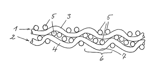
As may be seen in the clearest way from Figure 4,
the dewatering forming fabric of Figures 1 to 5 consists
of an upper layer 1 of transverse threads 3 and a lower
layer 2 of transverse threads 4 and 8 which are
interwoven with a single system of longitudina~ threads
5. The weave repeat is a 7 harness wsave which repeats
in the transverse direction after seven longitudinal
threads 5 and in longitudinal direction a~ter fourteen
transverse threads 3 of the upper layer 1 and fourteen
transverse threads 4 and 8 of the lower layer 2. In that
regard, each transverse thread 3 of the upper layer 1 is
positioned above a transverse thread 4, 8 of the lower
layer, so that the transverse thread density is the same
in the upper layer 1 and in the lower layer 2. Each
Longitudinal thread S is woven, per repeat, twice into
the upper layer 1 in a manner such that it is passed over
two transverse threads 3, under one transverse thread 3
and then again over two transverse threads 3 and then to
the lower layer 2. In a 7 harne~s weave, the course of
~ s~
,
~L3~077
adjacent longitudinal threads may, for instance, alwaye
be offset by six transverse threads in one direction
i.e., the so-called count number i~ six, which iB
equivalent to a doubled ~ atla The weave of the upper
layer and hence the structure on the papex side is the
same as that shown in U.S. Patent 4,739,803.
Accordingly, there exists in the upper layer 1 a
heterogeneous supporting of the transverse threads 3,
with a transverse thread 3 always being supported b~ a
single longitudinal thread 5 as in a saddle and therefore
extending precisely in the transverse direction. The
adjacent transverse threads are supported in shearlike
manner by two successive longitudinal threads 5, with the
longitudinal thread 5 descending, after completion of the
float, to the lower layer 2 as the other longitudinal
thread 5 is just ascending from the lower layer 2 in
order to float on the paper side. Both types of support
of the transvers~ threads 3 alternate on the paper side.
On account of that, successive transverse threads 3 do
not form on the paper side any parallel floats butl
rather, the floats are disposed at an angle relative to
one another, whereby the marking characteristics of this
dewatering fabric are improved. After thermofixation,
all floats of the longitudinal threads 5 and of the
transverse thread 3 on the paper side are disposed in
one plane.
~`
~ 3t 6~77
After interweaving into the upper layer 1, the
longitudinal thread 5 extends over an intermediate
stretch of three transverse threads between the layers 1,
2 and is subsequently thereto likewise interwoven twice
with the transverse threads 4, 8 of the lower layer, the
longitudinal thread 5 in that connection extending in the
interior of the fabric, between these two binding points
over two transverse threads 4, 8. Accordingly in the
lower laye.r 2, the longitudinal thread 5 is wound around
a transverse 8 on the underside~ is positioned over two
transverse threads 4, .8 and is again wound around a
transverse thread 4 on the underside. Thereupon, there
follows an intermediate stretch of two transverse threads
to the next bonding point into the upper layer 1. The
couxse of the longitudinal thread 5 is unsymmetrical.
The weave pattern is irregular in the lower layer 2 in
: that the first transverse thread 8a (Fig. 1 and 5) of a
repeat is bound by the second longitudinal thrad 5b, the
; second transverse thread 4b by the fourth longitudinal
thread 5d, and in that the third transverse thread 8c is
not bound by the sixth 5f but, rather, by the seventh
longitudinal thread 5g, the fourth transverse thread 4d
by the ninth longitudinal thread 5b (- second
: longitudinal thread of the repect following at the reight
side) and the fifth transverse thread 8e again not by the
eleventh (or fourth), buk rather the twelfth (or fifth)
longitudinal thread 5e. As a result the desired
structure is achieved on the running side, such as it is
\~
J ~
~31~77
-- 10 --
depicted in Figure 1, with successive transverse thread~
4, 8 when viewed in cross-section (Figures 2 and 3)
exhibiting asymmetrical floats.
The upper and lower layers 1, 2 are comprised of
transverse threads 3, 4, 8 which are interwoven with a
system o longitudinal threads 5. The transverse threads
4, 8 of the lower layer 2 form transverse thread floats
6, each having a lowest point 7 which is offset from the
center of each float toward one side. 5uccessive
transverse threads 4, 8 of the lower layer 2 form pairs
and within a pair the lowest point 7 of the transverse
thread floats 6 are in alignment in a longitudinal
direction and the lowest point 7 of the f~oat of one
.transverse thread 4 of a pair is offset from the enter of
said float 6 in the direction opposite to the direction
in which the lowest point 7 of the float 6 oF the othPr
: ~ transverse thread of the pair is ofset.
The longitudinal threads 5 have a diameter of 0.15
mm and oonsist of low-stretch polyester (type 940 by
Hoechst). Their density is 63/cm. Subse~uent to
fixation, the longitudinal thread density increased to
72/cm~ In the upper layer 1, transverse threads having a
diameter of 0.15 mm and made from soft polyester (type
900 by Hoechst) are interwoven at a density of 34/cm.
: 25 Transverse threads 4, 8 havin~ a diameter of 0.18 cm are
: interwoven into the lower layer. Transverse threads 4
consist o~ a soft polyester ~type gon by ~oechst) and the
transvsrse threads 8 consist of polyamide PA6. The
density of the transverse threads was reduced on account
of fixation in the upper layex 1 and in the lower layer 2
to 32/cm. After fixation, the uppermost points o all
threads on the paper sid~ of the dewatering fa~ric are
located in one plane. The height differential between
the transverse threads 4, 8 and the longitudinal threads
5 on the running side is 9.5/100 mm, so that upon use o
the dewatering fabric the transverse threads 4, 8 must be
completely chafed through before the longitudinal threads
5 chafe through.
In the illustrative embodiment shown in Figures 6 to
10, the longitudinal thread 5 in the upper layer 1 passes
over three transverse threads 3. ~he transverse threads
3 alternately have a diameter of 0.18 and 0.12 mm and are
woven in a manner such that the center transverse thread
3 within a longitudinal thread float on the paper side is
: of the smaller diameter. In that regard, the transverse
threads 3 of different thickness also take a different
course such that the finer transverse threads 3 are lying
: completely upon the paper side of the dewatering fabric,
i.e. the longitudinal thread 5 is never wound around them
from the top or, expressed in other wordst the warp
~25 threads 5 never pass over a fine transverse thread 3 and
:after that between this transverse thread 3 and the
succes~ive, thicker transvexse thread 3 (EP-A-O 085 353).
~,:
,
-~ ~316077
- 12 -
In the lower layer 2 the longitudinal thread 5 binds
the transverss threads 4, 8 in the same way as in
illustrative embodiment shown in Figure 1 and 5. In the
lower layer 2 the tran~verse threads 4, 8 have a diameter
of 0.20 mm and are likewise made alternately from
ployester and polyamide, as in the case of the
illustrative embodiment shQwn in Figures 1 to 5.
,:
~: :
.~ :
,
~,~
;
, .