Note: Descriptions are shown in the official language in which they were submitted.
- 1 1 31 621 ~
The present invention relates to a method and a device for
~ault location in the event of a fault on a power
transmission line.
For protection of cables and overhead power transmission
lines so-called distance protection devices are used. These
may be based on different technical principles, often based
on a certain region of operation in an impedance plane or in
the form of a wave detector based design. In this
connection it is normally desirable to find out the distance
from a measuring station to a possible fault and also to be
able to determine the magnitude of the fault resistance.
The distance protection devices therefore often comprise so-
called fault locators. The present invention comprises a
method and a device for achieving better performance when
determining the distance to a faul-t from a measuring station
as well as the magnitude of the fault resistance.
According to the present invention there is p ro v i d e d a
method for determining the location of a fault at a ault
position (F) on a power transmission line between two
stations (P, Q) and in W}liCh the power transmission line has
an known conduction impedance (ZpQ), comprising, at one of
the stations (P), the steps of:
25 - measuring the phase vol-tage (UpM) w~th capacitlve
voltage measuring transformers:
- measuring the phase currents (Ip) or changes in the
phase currents (~Ip) on the occurence of a fault;
- low pass filtering the phase voltage and the pllase
currents or changes in the phase currents: and
- converting the filtered phase voltage, phase currents
or the change in the phase currents from an analog to
instantaneous digitized phase voltage, phase currents
or chan~es in phase current values, re~pectively:
,~
.,~
- la - 1 31 621 ~
the method further comprising the steps of:
- calculating a value of the fault distance a and a value
of an apparent fault. resistance RF at the fault
location, using linear regression, on the basis of the
relationship:
UPM = aZpQIp ~ RFIp + ~UcvT
- where a represents a measure of-the fault position,
RFIp represents a voltage across the fault position and
aucvT represents a fault voltage introduced by the
capacitive voltage measuring means;
- comparing the fault distance with an upper (a max) and
a lower (amin) limit value and comparing the apparent
fault resistance RF with an upper (RFmaX) and a lower
(RFmin) limit value and generating a tripping signal
when the fault position a and the apparent fault
resistance RF are within predetermined limits.
According to the present invention, there i8 a.lso provided a
device for determining the location of a fault at a fault
position (F) on a power transmission line between two
stations (P, Q) and in which the power transmission line has
an known conduction impedance (ZpQ), comprising at one of
the stations (P):
- capacitive voltage measuring transformers means for
measuring the phase voltage (UpM):
- means for measuring the phase currents (Ip) or changes
in the phase currents (~Ip) on the occurrence of a
fault;
- means for low pass filtering the phase voltage and the
phase currents or changes in the phase currents; and
- means for converting the filtered phase voltage, phase
currents or the change in the phase currents from a.n
~. .
, ~ '
- lb _ 1 3t 62t 4
analog to instantaneou6 digitized phase coltage, phase
currents or changes in phase current values,
respectively:
the device further comprising:
- means for calculati~g a value of the fault distance
a and a value of an apparent fault resistance R~ at
the fau~t location, using linear regression, on the
basis of the relationship:
PM PQ P F P ~UCVT0 ~ where a represents a measure of the fault position,
Ip represents a voltage across the fault position and
~UcvT represents a fault voltage introduced by the
capacitive voltage measuring means: and
- means for comparing the fault distance a with an upper
(amaX) and a lower (amin) limit value and for comparing
the apparent fault resistance with an upper (RFmaX) and
a lower (RFmin) limit value and generating a tripping
signal when the fault position and the apparent fault
resistance, respectively, are within the afo~esaid
limit values.
The prior art and preferred embodiments of the invention
will now be described on the basis of and with reference to
the following figures:
Figure 1 shows an imaginary line between stations P and Q on
which a fault to ground has arisen at F. Otherwise, the
figure comprises the voltages, currents, impedances, and so
on, included in the description.
Figure 2 ~how~ an equivalent diagram for a capacitive
voltage measuring device, a so-called CVT transformer.
lc - 1 ~1 621 4
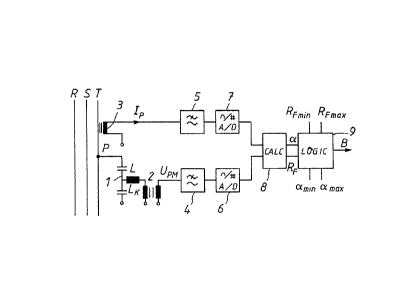
Fi~re 3 shows a device according to the invention for
determining the fault position and the fault resistance.
The principles of fault location and determination of the
S fault resistance when a fault has occured on a protected
line distance
/
/
/
1316214
- ld -
a and a value of an apparent fault resistance RF at
the fault location, using linear regression, on the
basis of the relationship:
UPM = aZpQIp + RFIp + ~UcvT
- where a represents a measure of the fault position,
RFIp represents a voltage across the fault position and
~UcvT represents a fault voltage introduced by the
capacitive voltage measuring means; and
- means for comparing the fault distance a with an upper
(amax) and a lower (amin) limit value and for comparing
the apparent fault resistance with an upper (RFmaX) and
a lower (RFmin) limit value and generating a tripping
signal when the fault position and the apparent fault
resistance, respectively, are within the afo~esaid
limit values.
The prior art and preferred embodiments of the invention
will now be described on the basis of and with reference to
the following figures:
Figure l shows an imaginary line between stations P and Q on
which a fault to ground has arisen at F. Otherwise, the
figure comprises the voltages, currents, impedances, and so
on, included in the description.
Figure 2 shows an e~uivalent diagram for a capacitive
voltage measuring device, a so-called CVT transformer.
Figure 3 shows a device according to the invention for
- 30 determining the fault position and the fault resistance.
The principles of fault location and determination of the
fault resistance when a fault has occured on a protected
line distance
~ I r, ~
2 1 31 621 ~
are well known. The basis normally consists of measured values
obtained with the aid of measuring transformers in a measuring
station located adjacent to the protected line. Present_day
technique comprises analog-to-digital tA/D) conversion and fil-
tering of the measured values which then, via different distanceprotection equations, determine the fault distance and the mag-
nitude of the fault resistance. To be able to describe the
invention in the best way, a brief summary will first be given
of distance protection equations which are often used and of
how these are solved according to the prior art. Finally, the
problems which arise in connection with the determination of
fault distance and fault resistance, depending on the measuring
principles used, will also be described.
As indicated above, there are several alternative distance pro-
tection equations. Two of the most ordinary ones will be brief-
ly described with reference to Figure 1. Both of these pre-
suppose knowledge of the faultless line impedance ZpQ on the
protected line distance between two measuring stations P and
Q, After the determination of a fault, the voltages Up and UQ
and the currents Ip and IQ can be measured in the respective
stations. In order to eliminate the need for communication
between the stations, however, the values at one of the stations
are normally the starting-point. If the assumption is made that
` a current IF flows through a fault resistance RF, whereby a
voltage UF lies across the fault resistance, the following
relationship can be set;
P UPF + UF = ~UpQ + UF = ~ZpQIp + RFIF (1)
Here,c~(= 0 - 1) is, for the time being, an assumed measure of
the fault position and UpQ is a voltage drop across the whole
line reconstructed with the aid of Ip,
Equation (1) is, of course, not directly solvable because of
too many unknown parameters and therefore a certain amount of
assumptions must be made to be able to solve it. In a conven-
tional distance protection device, it is common to assume that
3 1 31 62 ~ 4
the fault current IF is proportional to the current measured
in station P, i e.
IF = k1Ip ~2)
This assumption is fulfilled if the e.m.f. s Ep and EQ at P and
Q have equal phases and if the phase angles for the impedances
counting from the fault location F to the respective e.m.f. are
equal. Equation (1) can then be written as follows
Up = ~ZpQIp + RF . klIp = ~ZpQIp + RF1Ip (3)
where RF1 is an apparent fault resistance during the calcula-
tion.
Another variant of the necessary assumption is to assume that
the fault current is proportional to the ~urrent change at P
when a fault has occurred, i.e.
IF ~ k2~Ip (4)
whereby equation (1) can be expressed as
U = ~ZpQIp + RFk2 ~Ip = d ZpQIp + RF2~ P
Both equations (3) and (5) comprise two unknown parameters, 5~
and RF1 or RF2, respectively. This means that a special method
-- of solution is needed to be able to solve these unknown para-
meters. Such a method may be a linear regression, a technique
which has been described in detail in, for example, Ljung-
Soderstrom s "Theory and Practice of Recursive Identification",
1983, espccially pages 323-327. Suitably, a form of linear
regression is also used, which comprises a forgetting factor
in order to adapt equations (3) and (5) to the existing mea-
suring conditions.
A summary of the used technique is given in, inter alia, Swedish
patent application 8702683-7, "Frequency relay", pages 5-10.
1316214
The method using linear regression and the least square method
to solve distance equations of the same types as (3) and ~5)
is also described in an article entitled ~A Prototype of Multi-
processor Based Distance Relay", published in IEEE Transaction
on Power Apparatus and Systems, Vol. PAS-101, No. 2, February
1982, pages 491-497.
When distance protection devices with fault location and deter-
mination of the fault resistance are used for high voltage trans-
_ mission, capacitive voltage transformers, CVT, are usually used
for the voltage measurement. It is well known that such voltagemeasurement, especially in the case of a large amplitude reduc-
tion in connection with the occurrence of the fault and espe-
cially if the fault occurs at the zero passage of the voltage,
causes a measurement error voltage, generally called CVT tran-
sients. This is described, among other things, in an articleby N. Ashton in Power System Protection, part 1, pages 279-283,
published by P. Peregrinus Ltd., Stevenage UK, Hertz 1981, New
York. There is a relatively simple physical explanation of this.
The equivalent diagram for such a voltage measurement will be
clear from Figure 2. Here, Up is the high voltage to be measured
and UpM is the measured voltage delivered by the capacitive vol-
tage transformer.
A CVT measurement comprises, in addition to a capacitive voltage
divider C, a compensating inductor LK and an ordinary magnetic
transformer whose burden is symbolized by the inductance LB and
the resistance RB.
The transmission function UpM/Up will consequently be
UPM RB + sLB (6)
By choosing LK and C so that
i ~oLk + j6~oC =
where ~0 corresponds to the mains frequency fO, the transmission
1316214
function at mains frequency will always be
Gc~T(j~0) = 1 (8)
independently of the load and the power.
However, at low frequencies the transmission function will be
sRBC
GCVT(~ sRBC (9)
which leads to an aperiodic transient with a time constant
T = RBC after a voltage change. For a typical load of 150 VA,
T will normally vary between 50 and 150 ms.
When fault situations arise, decisions on what actions to take
to prevent harmful influence are usually very urgently required.
For the very rapid evaluation methods that are nowadays available
to determine the unknown parameters in equations (3) and (5),
the incorrect measurement error voltage, introduced by the CVT
transformer~ involves extensive, incorrect evaluations and con-
clusions. Since the CVT transients have been known for a longtime, different methods have also been used to reduce the effect
of these. The most frequently used means have been to filter
out the CVT transients in various ways. The disadvantage of
such a method is then also a delay of a true evaluation.
Because of the introduced CVT measurement error voltage, the
above-mentioned assumptions as regards the distance protection
equations will entail considerable errors in the determination
of fault position and fault resistance. It has also been found
that the measurement error voltage mainly has a low frequency
spectrum. According to the invention, the distance protection
equations described above will therefore be supplemented by
a voltage ~UcvT which is intended to represent the low
frequency measurement error voltage. This means that the
distance protection equations can be generally described as
.
' ' 6 1 31 621 4
UPM = UpM ~true) + ~ UcvT (low frequency) = ~UpQ ~ UF +
UCVT ` (10)
which equation gives rise to the increased instantaneous value
models
PM1 = ~ ZpQIp + RF1Ip + auCvT t 11 )
and
PM2 PQ P F2 Ip + UCVT (12)
Thus, the invention comprises starting from any of these
assumptions and tryin~ to find the parameters ~, RF1 or RF2 and
~UcvT by linear regression. Simulations have shown that with
this assumption a cOnsiderable improvement of the determination
of fault positions and apparent fault resistances has been obtained.
The most important information received is, of course, the value
Or ~; Since normally measurement is performed in only one sta-
tion, no direct measure of the previously described constantsof proportionality k1 and k2 can be obtained, This means that
the real fault resistance RF cannot be stated. Since the distance
relays normally work in the 1st guadrant of the impedance plane,
the relay must not, of course, trip for a load resistance which
lies within the transmission capacity of t,he line, The limit
values for the resistance which are to result in tripping (see
further under DESCRIPTION OF TlIE PREFEnnED EMBODIMENTS), must
therefore be indicated on the basis Or normal load and an assumed
value of k1 or k2 and of the apparent resistance ~F1 or RF2,
respectively.
Normally, up to 80-90% of the line distance is covered by the
fault location.
A preferred embodiment of a device for fault location accordin~
~lr~ -
7 1 31 621 ~
to the invention will be clear from Figure 3. On a high voltage
network RST and at a measuring station P, phase voltages Up and
phase currents Ip are measured, As will have been clear from
the foregoing description, at least two different distance pro-
tection equations (11) and (12) can be made the starting-point.
If equation (11) is made the starting-point, the device for
fault location is continuously switched in and controls the state
of the line. If equation (12) is made the starting-point, a
least prescribed change of Ip must be assumed to initiate the
control of the state of the line. These are obvious conditions
for a distance relay and will not, therefore, be further described.
As described above, the measuring voltage UpM is obtained via
a capacitive voltage divider 1 and a conventional transformer
2. The current Ip is measured in conventional manner with a
current transformer 3.
The measured values are low-pass filtered in filters 4 and 5,
frequencies in excess of 500 Hz normally being filtered out and
converted to digital representation in devices 6 and 7. The
instantaneous digitized current and voltage values are supplied
to a calculator ~CALC) 8, which processes any of the described
models according to (11) and ~12) by means of linear regression
technique. This results in estimated values of the parameters
of the equations, that is, ~ which represents the fault position,
RF1 and RF2, respectively, which represent the apparent fault
resistance, and ~UcvT which represents the fault voltage
The voltage ~ UcvT is, strictly speaking, of no further interest.
The values of ~, RF1 and RF2, produced by the calculator, are
supplied to a logic unit (LOGIC) 9 for co~parison with inputted
upper and lower limit values ~ in' ~max' RFmin a Fmax'
pectively. If the obtained ~- and RF_values lie within the
stated limits, a decision B to trip is given.
The alternative embodiments which are available entail more or
less integrated combinations of the devices for filtering, for
1316214
conversion to digital representation, for the linear regression
and for the necessary logic decisions.
,: