Note: Descriptions are shown in the official language in which they were submitted.
:13 ~ ~ 3 ~ ~
250~7-73
BACKGROUND OF THE INVENTION
Field of -the Invention
This lnvention relates to methods of oscillating molds
for continuous casting at high frequencies and molds oscillated by
such methods. More particularly, it relates to methods of
oscillating at high frequencies molds that are used in the
continuous casting of billets, blooms and slabs of metals and
molds that are oscillated at high frequencies while such semi-
finished products of metals are being continuously cast.
Description of the Prior Art
It has been known to provide a large number of high-
frequency oscillating means (hereinafter called oscillators) on
the mold to oscillate the inner wall of the mold near the meniscus
of liquid metal during the continuous casting operation, as, for
example, is disclosed in Japanese Provisional Patent Publication
No. 55742 of 1987.
Oscillators having the same oscillating characteristics
are commonly employed. Furthermore, a set of oscillators used in
the conventional oscillating methods accomplish oscillation with
the same frequency. Therefore, the high-frequency waves
transmitted from the oscillators interfere with each other at the
interface between the inner lining and liquid metal or the
solidified shell. If the high-frequency waves from the two
sources are of the same phase, the amplitude of frequency will be
doubled to cause violent oscillation. On the other hand, the
amplitude at point where the path difference = /2 (where
wavelength of high-frequency wave) will become very small, wi-th
l ?
~, .
-.
.
,
,, ,. ,, , :,...... .
' ' ' ' ';
~3~32~ 25087-73
the high-frequency waves from the oscilla~ors offsetting each
other. The result ls the occurrence oE seizure or sticking.
In the method of oscillating a mold provided with a
plurality of oscillators according to Japanese Provisional Patent
Publication No. 57742 of 1987, the difference between the high-
frequency waves generated by adjoining oscillators for the
oscillation of the inner lining is kept within the limit at which
beat is produced.
The frequency of the waves generated by one oscillator
can be varied by controlling the frequency setter. The method of
Japanese Provisional Patent Publication No. 57742 of 1987 greatly
varies the frequencies of the individual oscillators~ But if the
oscillators have the same oscillating characteristic, the
amplitude of high-frequency waves produced by some oscillators is
then decreased so greatly that the inner lining is not oscillated
with large enough amplitudes. If, on the other hand, oscillators
of different types having different oscillating characteristics
are used, difficult problems will arise in the control and
management thereof.
The separately excited oscillation generator that drives
the oscillator is an open-loop control system in which power
varies with variations in load (or variations in impedance).
Therefore, it has been difficult to keep constant the amplitude of
osclllation. With light loads, the amplitude of oscillation
varies greatly as frequency varies. Such oscillations are
common~ly controlled by such automatic frequency tracking constant
amplltude control circuits.
,~''
:
.
,
~ 32 i 25087-73
With the automatic ~requenc~ tracking constant amplitude
control, however, it is impossible to arbitrarily vary the
frequency of oscillations produced by adjoining oscillators so
that the amplitude of oscillations in the area to be oscillated is
effectively Elattened. This can result in uneven amplitude that
leads to seizure and sticking.
Exposed to rapidly flowing cooling water and oscillated
at high frequencies, the water-cooled oscillated surface of the
inner lining is susceptible to cracking and erosion. Japanese
Provisional Patent Publications Nos. 197,351 and 197,348 of 1984
disclose methods of preven-ting such cracking and erosion by
covering the weak spot in the water-cooled oscillated surface with
a sheet of cushioning material or alloyed metal. Although
effective in decreasing the occurrence of cracking and erosion,
those methods are not without problems. In the course of long-
time service, for example, water may penetrate into a space
between the attached covering material and the water-cooled
oscillated surface, causing erosion. The covering material coming
off may clog up the cooling water passage. A more important
problem is that the covered portion of the inner lining is not
cooled adequately. Such being the case, development of a better
oscillated mold capable of
,.~b ~.
- ,
-
.
.
, ~ :
,
~1&~2~
withstanding long-time service has been awaited.
Oscillators are usually cooled by water-cooling, air-
purging or other means as overheating can result in their
breakage. If any of the oscillators malfunctions, the
composite oscillation applied to the mold will become
different from the originally intended one, thereby
impeding the smooth implementation of the continuous
casting operation. Permitting no water cooling because of
the insulation consideration necessitated by -the applied
voltage as high as, for example, 4000 Vp p,
electrostrictive oscillators are cooled by air-purging
etc. Because air-purging and other similar cooling
methods are not so effective as water-cooling, operation
of the electrostrictive oscillators should be watched
carefully.
Monitoring of oscillators has been performed by
measuring the voltage and current of the power supply
servicing the oscillators. But it is difficult for this
method to grasp the degree of deterioration in the
elect~ostrictive elements in the oscillators because it
does not perform direct measuremen~ of oscillations.
Therefore, oscillators often break unexpectedly, offering
an obstacle to~ the continuous casting operation. Another
conventional method of monitoring the operation of
oscillators measures amplitude with an amplitude detector.
~But this method is costly because a large number of
amplitude detectors and amplifiers must be provided to
. ~ .
131~
cover a large number of oscillators attached to the
oscillated mold. Furthermore, this method has not been
very reliable because amplitude detectors are apt to come
off easily. "Handbook of Ul-trasonic Technologies" (Nikkan
Kogyo Shimbum~ discloses, between pages 488 and 490,
various types of pickup sensors that can be used for
measuring microamplitudes of oscillating solids. But they
are costly and difficult to attach. Their sensors are apt
to come off during the long-time service. They need much
larger installation space than the high-frequency
oscillated mold of continuous casters can afford.
Summary of the Invention
An object of this invention is to provide a method of
constantly imparting desirable oscillations to all surface
of the inner lining near the meniscus in a continuous
caster mold equipped wlth a large number of oscillators
having the same oscillating characteristic by controlling
the interference between the high-frequency waves
transm`itted by the individual oscillators.
; Another object of this invention is to provide a
method of constantly imparting desirable oscillations to
all surface of the inner lining near the meniscus in a
continuous caster mold equipped with a plurality of such
high-frequency oscillators that the frequencies of oscil-
lations produced by any two adjoining oscillators are dif-
ferentiated by arbitrarily varying the frequency of each
oscillstor and permitting a constant amplitude control.
~:
,j .,
.
- ' , : -
Still another ob,ject of this invention is to provide
an oscillated mold that produces no cracking or erosion on
the water-cooled oscillated surface of the inner lining
even if used over a long period of time.
Yet another object of this invention is to provide an
oscillated mold equipped with an easy-to-use monitoring
device that permits the operator to learn that the
individual oscillators on the mold are accomplishing the
desired oscillation.
To accomplish the above objects, a method of
oscillating a continuous-caster mold at high frequencies
according to this invention installs a plurality of
oscillators having practically the same oscillating
characteristic at appropriate intervals and along a line
where the surface of the liquld metal contacts the inner
lining of the mold or in the vicinity thereof. The tip of
each oscillator is connected to the inner lining so that
the axis of the oscillator extends at right angles to the
inner lining. Power is supplied to the individual
oscillators so that the frequencies of oscillations
produced by~any two adjoining oscillators are
differenciated from each other by not more than 2 KHz.
Thus, such two adjoinlng oscillators oscillate the inner
lining at right angles to the surface thereof at different
frequencies. The oscillators may be either of the
electostrictive type or of the magnetostrictive type.
~ In the oscillating method just described, one
: : , // i.
'. ' ~ '
.. -'': ' -.
. .
C ~
oscillator may be chosen as a base oscillator, with the
frequencies of oscillations produced by the other
oscillators gradually decreased or increased according to
the distance at which such oscillators stand away from the
base oscillator. Also, the frequencies of oscillations
applied by the individual oscillators on the inner lining
may be varied with time, either intermittently or
continuously. By choosing a base oscillator, furthermore,
a first oscillation mode, in which the frequencies of
oscillations produced by the other oscillators are
gradually decreased according to the distance at which
such oscillators stand away from the base oscillator, and
a second oscillation mode, in which the frequencies of ',
osclllations are gradually increased according to the same
distance, may be set. Then, the inner lining may be
alternately oscillated in the first and second modes that
are switched with time, either intermittently or
continuously.
To avoid any significant variations in the
frequencies of oscillations produced by a plurality of
oscillators attached to the oscillated mold, this
invention uses oscillators of the same type having the
same oscillating characteristic. This facilitates
oscillation control and permits reducing equipment cost.
No localized spot of the mold is constantly
oscillated with small amplitudes. Instead, the whole mold
is through].y oscillated with large amplitudes. This
~ AY
.
.
`, , :`
. ~ . ,... .. `
, ~ ~
. .
3 h j
assures smooth inflow of flux t avoids the seizure and
sticking between the liquid metal and the mold inner
lining and, thereby, prevents the occurrence of such
accidents as breakout. The results are an improvement in
the surface quality of cast products, the facilitation or
elimination of conditioning, and a remarkable improvement
in production yield and operation efficiency.
In the above oscillating method, power supply to the
oscillators may be performed through a high-frequency
output transformer, with the product of the d.c. voltage
and d.c. current on the primary side of the transformer
controlled so that the amplitude of the produced
oscillations is kept constant. It is also possible to
detect the d.c. voltage and d.c. current on the primary
side of the high-frequency output transformer for use in
the feedback control thereof.
The control circuit according to this invention,
which controls frequency by a simple separate excitation
method and controls amplitude by controlling power supply,
is not costly to make and easy to maintain. This
invention has made it possible to arbitrarily vary the
frequency of individual oscillators and to perform
constant amplitude control. Consequently, the entire
surface of the mold inner lining near the meniscus can
now be oscillated as desired.
~ A continuous caster mold oscillated at high
frequencies is made up of an inner lining fabricated from
~ ;. }~ ~
'
copper or copper alloy and a backup outer plate, with a
cooling water passage proviced between the inner lining
and outer plate. The water-cooled surface of the inner
lining is nickel-plated. The nicekl-plated surface may
further be plated with chromium.
This invention has drastically reduced the cracking
and erosion in the water-cooled oscillated surface,
thereby remarkably prolonging the service life of the
oscillated mold.
The continuous caster mold oscillated at high
frequencies according to this invention is also equipped
with a temperature sensor to measure the temperature at
the surface of the oscillator, a temperature checker that
checks if the surface temperature of the oscillator is
within the desired range, and an alarm that actuates a
signal when the surface temperature is outside the desired
range.
These devices assure a more reliable monitoring of
the oscillating condition of many oscillators attached to
the mold. They make it easier to keep the oscillations
produced by the individual oscillators within the desired
range. In addition, they provide data on the level of
oscillator deterioration through continuous monitoring.
All this permits preventing troubles in the continuous
casting operation that have heretofore been unforeseeable.
Brief Description of the Drawings
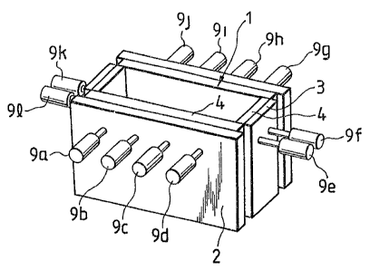
Fig. 1 is a perspective view of an oscillated
'
, ~ 7
",
.
~. ~., :. . .
.
.~ .
~ 3 ~
continuous caster mold equipped with a plurality of
oscillators;
Fig. 2 is a schematic diagram of oscillators attached
to a continuous caster mold;
Fig. 3 illustrated the interference of high-frequency
waves transmitted from two oscillators at the surface of a
mold inner lining;
Fig. 4 diagrammatically show conventional examples of
composite oscillations resulting from the interference
shown in Fig. 3;
Fig. 5 graphically shows the relationship between the
frequency and amplitude of oscillation produced by an
oscillator;
Fig. 6 graphically shows the relationship between
frequency and amplitude, using the applied load as the
parameter;
Fig. 7 shows a bridge circuit to detect the amplitude
of oscillation;
Fig. 8 is a block diagram of a conventional automatic
frequency -tracking constant amplitude controller;
Fig. 9~is a perspective view of a mold for a
continuous steel bloom caster equlpped with oscillators;
Fig. 10 is a perspective view of an inner lining of a
mo~d;
Fig~. 11 is a cross-sectional view of a portion of a
mold where an oscillator is attached;
Fig. 12 is a block diagram showing a preferred
:, `' ~ '
.
embodiment of an oscillating device according to this
invention;
Fig. 13 is a circuit diagram showing an ex~mple of a
frequency generator;
Fig. 14 diagrammatically shows amplitudes of
composite oscillations produced by the method and
apparatus of this invention;
Fig. 15 diagrammatically shows the arrangement of m
pieces of oscillators and the amplitude of composite
oscillations produced thereby;
Fig. 16 graphically shows models of set frequencies
for different oscillators on a mold;
Fig. 17 graphically shows an example of resonance
frequency that is measured in determining the reference
frequency;
Fig. 18a shows the distribution of amplitudes that
varies with the position of three oscillators producing
oscillations of different frequencies; Fig. 18b shows the
points at which the three oscillators are positioned;
Fig. 19 shows the distribution of amplitudes with a
mold inner lining oscillated by four oscillators producing
oscillations of different frequencies;
Fig. ZO graphically shows the empirically confirmed
relationship between power (voltage times current) and
amplitude;
Flg. 21 graphically shows the maximum amplitudes at
different points of a mold inner lining at different time;
:::
~ 31 ~ 3 ~, ~
In Fig. 22, (a) graphlcally shows the maxlmum amplltudes
at different points of a mold oscil]ated in the pattern shown in
Flg. 21; (b) ls a slmllar graph obtalned wlth a dlfferent
osclllation pattern; (c) is a slmllar graph obtalned by
intermittently alternating the patterns (a) and (b);
In Fig. 23, (a) graphically shows the maximum amplitudes
at dlfferent points of a mold osclllated whose frequency of
osclllatlon ls varled wlth tlme as set under condltion I; (b) ls a
slmllar graph obtained with the setting under condition II; (c) is
a simllar graph obtalned by lntermittently alternating the
settings under condltlons I and II;
Fig. 24 graphically shows how the frequency of
oscillations produced by different osclllators varles as the base
oscillator is changed;
In Flg. 25, (a) ls a perspective view of an oscillator
equipped wlth a thermocouple, and (b) is a front view of the same
oscillator;
Fig. 26 graphically shows an example of the surface
temperature distribution in an oscillator at work; and
Fig. 27 is a block diagram showing an example of a
monitoring system.
Descri~tion of the Preferred Embodiments
To facilitate the understanding of this invention, the
problems inherent in the conventional methods of oscillating molds
at high frequencies and the molds oscillated by the same methods
will be discussed in more detail before proceeding to the
description of a preferred embodiment of this invention.
12
-
.
~ 3~3~,~
25087-73
Figure L ~shows an example of a continuous caster mold 1
provided with oscil]ators 9a to 91. The mold 1 has an inner
lining of copper 4 on -the inside of broad-face plates 2 and
narrow-face pla-tes 3. The inner lining 4 is oscillated by the
oscillators 9a to 91 connected thereto. To prevent the sei~ure or
sticking of liquid metal to the
13
., -- . . ~ i .", :
.
'
.
~ 25087-73
inner lining of the mold 1, it ls neces~ary to
continuously oscillate the entire sur~ace of the inner
lining 4 of the mold 1 near the meniscu~ at de~ired
~requencies. To the o~cillators 9a to 91 are connected a
frequency generator 6, a power setter 7 and an amplifier 8
successively, as shown in Fig. 2. The frequency generator
6, power 8etter 7, amplifier 8 and o~cillators 9a to 91
constitute a set o~ o~cillaking means 5. The o~cillating
mean~ 5 ~ets the frequency and power wlth whlch the inner
lining 4 is osclllated.
Oscillators havlng the same oscillating
characteristics are commonly employed. Furthermore, a set
of oscillators used in the conventional oscillating methods
accomplish osclllatlon wit~ the same frequency.
Therefore, the high-frequency wave~ transmitted from the
o~c~llators A and B interfere with each other at the
interface between the inner lining 4 and liquid metal or
the solidi~ied ~hell M, as ~hown in Fig. 3. Ir the high-
frequency waves from the two 80urces are of the same
phase, the amplitude of frequency will be doubled to cause
violent oscillation at point Pl on the inner lining that
i8 at di~tance APl ~ BPl. On the other hand, the
amplitude at point P2 where AP2 - BP2 ~ ~/2 (where ~ =
wavelength of high-frequency wave) will become very small,
with the high-frequency waves from the o~clllators A and B
offsetting each other. The result is the occurrence of
seizure or ~ticking.
I4
,,~
,
:
.
.- ~ -' ' .
,.
- ~
i 3 ~ J 2S087-73
Craph (a) of Fig. 4 shows how offsetting occurs at
point Pl. Dotted line shows the high-frequency wave from
the oscillator A, chain line showq that from the
oscillator B, and solid line indicates the composite waYe
obtained by combining the two, all at point Pl.
Slmilarly, graph (b) of Flg. 4 show~ the offsetting
condition at point P2.
In the method of o~cillating a ~old provided with a
plurality of o~cillators according to Japaneqe Provisional
Patent Publication No. 57742 of 1987, the difference
between the high-frequency wave~ generated by ad~oinlng
o~cillators for the oscillation of the inner lining is
kept within the limit at which beat is produced.
The frequency of the waveq generated by one
oscillator can be varied by controlling the frequency
setter. But if the frequency of an oscillator (of the
electrostrictive or magnetostrictive type) that produces
the maximum ampl~tude at frequency fO i9 lowered under (fO
- 1) KHz or raised above (fO + 1) KHz, the amplltude will
become very small as shown in Fig. 5. The method of
Japanese Provisional Patent Publlcation No. 57742 of 1~87
greatly varle~ the fr~quencies of the lndivldual
oscillators. But if the oscillators have the same
oscillating characteri tic, the amplitude of high-
frequency waves produced by some o~clllators is then
decrea8ed 80 greatly, as mentioned previously, that the
inner lining 19 not oscillated with large enough
.
~ 3 6 ~ 2 ~ 25087-73
amplitudes. If, on the other hand, osclllators Or
different type3 having different oscillating
characterlstics are used, difficult problemg will arise in
the control and management thereof.
The separately excited oscillation generator tha~
drives the o~cillator 18 an open-loop control system in
which power varies with variations in load ~or variations
in impedance). Therefore, it ha3 been difficult to keep
con~tant the amplitude of oscillation. With light loads,
the amplitude of oscillation varies greatly as frequency
varies, as indicated by dotted lines in Fig. 6. Such
o~cillations are commonly controlled by such automatic
frequency tracking constant amplitude control circuits as
are shown in Figs. 7 and 8.
This type of automatic frequency tracking con~tant
amplitude control circuits detect the amplitude of
osclllation by the use of the followlng equation~
expressing the relationships among the voltage E at the
oscillator terminal, current I, control impedance Zd~
speed of the mechanical terminal v and coefficient of
power A:
. .
ZdI ~ AV -(Zd ~ Zm)I ...(1)
ZmI = Av ...(2)
As shown above, the impedance of the oscillator i9
expre~sed as the sum of the control impedance Zd that is
independent of oscillation and the control impedance Zm
that depends on o~cillation. Therefore, the voltage
1G
' :' ' ' ; , ' :
: ' ' ,
.
~ ~ J
~ 3 ~ 25087-73
proportional to oscillation is obtained by subtracting the
voltage drop due to the control impedance Zd ~rom the
voltage at the ter~inal of the o~clllator. The bridge
circult of an oscillator and impedances Zl to Z3 shown in
Figo 7 is an example of concrete sensing methods commonly
employed for the detection of the output voltage E2 that
i8 proportional to ZmI.
Automatic frequency tracklng is accomplished by means
of a closed circuit formed by a high-frequency oscillator
amplifier circuit 14 (transfer function in the amplifier
circuit:~ ~ and the oscillation sensing circuit shown in
Flg. 7, which con~titutes a ~eedback clrcuit 17 (transrer
coefficient in the beedback circuit:~ ). The
oscillating condition in this circuit i9 as follows:
~ - 1 ...(3)
Then, the frequency to satlsfy the ~ollowing equation
i8 automatically chosen:
+ ~ = 2n~ (n: integer) ...(4)
The constant amplitude control circuit shown in Fig.
8 compare~, in a voltage comparison control circuit 13, an
output signal preliminarily set by the amplitude ~etter 12
with a signal produced by amplifying the voltage E2 from
the oscillation sen~ing circuit by a voltage input
am~lirier 18. Then, the voltage comparison control
circuit 13 inputs a control ~ignal lnto the oscillator
amplifier circuit 14 con3iating Or a resonant phase
circuit 15 and an output matching inverter 16 to control
,, ,,,,, , . .~ . ,
, -,, ' ' ,
, ~. .~ '
~. 3 ~ 25087-73
the output to the oscillator so that constant arnplitude is
maintained at all times.
With the automatic frequency tracking constant amplitude
control, however, it is impossible to arbitrarily vary the
frequency of oscillations produced by adjoining oscillators so
that the amplitude of oscillations in the area to be oscillated is
effectively flattened. This can result in uneven amplitude that
leads to seizure and sticking.
This invention has solved the above problems with the
conventional methods and molds. Continuous casting of steel
blooms will be described below as a preferred embodiment of this
invention.
Now preferred embodiments of this invention applied to
the continuous casting of steel blooms will be described in the
following:
..,~
, ~ . ~ . . . .
~, . , ~ . .
,
~ 3 ~
Mold
Fig. 9 shows a mold and the surroundings thereof. A
mold 21 consists of an outer wall made up of broad-face
water boxes 22 and narrow-face back plates 23. An inner
lining 24 is attached to each of the broad-face water
boxes 22 and narrow-face back plates 23 by means of
fastening bolts (not shown). The upper portion of the
inner lining 24, where thickness is reduced, forms an
oscillating segment 25 as shown in Figs. 10 and 11. There
is a juncture 26 of cooling water on the cooled side of
the oscillating segment 25. The inner lining 24 also has
a plurality of grooves 27 cut in one surface thereof. The
junctures 26 and grooves 27, in combination, provide
cooling water passages between the inner linings and the
broad-face water boxes 22 and narrow-face back plates 23.
Cooling water supplied from the broad-face water boxes 22
and narrow-face back plates 23 run through the water
passages to cool the inner linings 24. Connecting seats
28 are provided in the oscillating segment 25. The broad-
face water boxes 22 and narrow-face back plates 23 also
have holes 29 into which connect m g rods are inserted. A
connecting~rod 10 of an oscillator 9 passes through a hole
29. With the tip of the connecting rod 10 screwed into a
connectlng seat 28, the osclllator 9 is fastened to the
inner lining 24. The oscillators 9 are disposed along a
line where the surface of liquid metal contacts the inner
linings 24 of the mold 21 or in the vicinity thereof, and
f
'
spaced apart from each other at appropriate intervals.
To ensure that the poured liquid metal forms a sound
initial solidified shell, the inner lining 24 is
fabricated from copper or copper alloy having high thermal
conductivities, and cooled on the outer side. The inner
lining 24 is oscillated at high frequencies, as mentioned
previously, to prevent the liquid metal from sticking
thereto. To lower the temperature at the metal-lining
interface and prevent the attenuation of high-frequency
oscillations, the thickness of the inner lining 2L~ should
preferably be as thin as possible. The thickness of
commonly used inner linings is between a few millimeters
and tens of millimeters. The inventors studied the
causes for the cracks and erosion that occur in the
water-cooled oscillated surface 30. From the studies, it
was found that such cracks and erosion were due to what is
known as cavitation erosion. The running cooling water
ar.d high-~frequency oscillation alternately build up high
and low pressures in some area of the water-cooled
oscillated surface 30. The resulting formation and
collapsing of bubbles at and near the interface between
the water-cooled oscillated surface 30 and cooling water
cause a damage to the water-cooled oscillated surface 30.
It was also found that nickel plating or a combination of
nickel and chromium plating (with chromium plating
provided over nickel plating) is highly effective in
preventing such cavitation erosion. While pure nickel
' '
0
.
2 ;~
plating serves the purpose right, a nickel alloy
containing 2 persent to 8 percent of iron is preferable
because of the better adherence to copper or copper alloy
and the hardness as high as Hv 350. The nickel alloy
coating having such properties continuously protects the
water-cooled oscillated surface even after an over-coated
layer of chromium has worn off. The nickel coating is
between O.Ol mm and 1 mm in thickness. Heavier thickness
providing greater durability is preferred. The chromium
coating provided over an undercoat of nickel is hard
enough to provide adequate durability against cavitation
erosion. Provided over a nickel coating, the chromium
coating adheres firmly enough to provide adequate
protection to the water-cooled oscillated surface 30 over
a long time. The thlckness of the chromium coating
usually is between 10 ~m and 50 ~m. The nickel plating or
the combination of nickel and chromium plating may be
applied either over the entirety of the water-cooled
oscillated surface 30 or over a localized area or areas
that are susceptible to heavy cavitation erosion. A life
test conducted on the water-cooled oscillated surface 30
of an inner lining 24 covered with a nickel coating of 0.5
mm (containing 7.1 percent iron) and further wi-th a
chromium coating of approximately 30 ~m proved that the
surface would remain undamaged for 3000 hours.
Oscillating Device
As shown in Fig. 12, an oscillating device 31
,~
~ r~
~ 3 ~
comprises a frequency generator 32, a power setter-
comparator 33, an output matching inverter 34 and an
output transformer 35 that are connected one after
another. When a power setting signal is actuated, the
output matching inverter 34 supplies power to an
oscillator 9 through the output transformer 35 and an
impedance matching coil 36. A shunt 38 and a voltage
divider 41 are connected to the output matching inverter
34. While the shunt 38 detects the current on the primary
sidè of the output transformer, the voltage divider 41
detects the voltage thereon. Signals actuated on
detecting such current and voltage are amplified by
amplifiers 39 and 42 and then input into a power control
circuit 37 through arithmetic circuits 40 and 43. The
function of the arithmetic circuits 40 and 43 is to find
the square root of the output current and voltage from the
amplifiers 39 and 42. While input power is detected,
output power is fed into the power setter-comparator 33
for comparison with the preset power level. By so doing,
produced power is always ~ept equal to the preset power
level.
The oscillator 9 is of the electrostrictive type,
producing high-frequency oscillations when actuated by the
power from the output transformer 35. Each oscillator 9
oscillates at high frequencies the inner lining 24 through
the connecting rod 10. Having the same oscillating
characteristic, oscillators 9 are interchangeable. This
.,
.
.
: " ~ ' - ", ~
~3~.~3~ ~-
feature not only permits considerable saving in equipment
cost but also facilitates the design of mold oscillation
pattern by simulation or other technologies.
In addition to the frequency generator 32 connected
to the power setter-comparator 33, a different frequency
generator having a function, for example, to vary the
frequency of oscillation with time may be provided
separately. A frequency generator 51 shown in Fig. 13 is
of the type just described. The frequency generator 51
consists essentially of a constant frequency generating
circuit 52, a sweep generating circuit 56, a frequency
counter 63, a BCD (binary coded decimal) system 65 and an
output unit 67. The constant frequency generating circuit
52 equipped with a frequency setter 53 is used when there
is no need to vary the frequency of oscillation with time.
On the other hand, the sweep generating circuit 56 having
a center f`requency setter 57, a frequency scanning width
setter 58 and a cycle period setter 59 is used when the
frequency of oscillation must be varied with time.
Switching from the constant frequency generating circuit
52 to the sweep generating circult 56 and vice versa is
accomplished by means o~ a changeover switch 69. The
frequency counter 63 detects the frequency at which the
lnner llning 24 of the mold 21 is oscillated. On
receiving remote instruction signals from a control panel
(not~shown), the ~CD system 65 determines whether the
oscillator 9 should be oscillated with constant frequency
G ~ ~
.
- :
~3~32 ~
or sweep frequency and performs switching from one mode to
the other. The output unit 67 has a plurality of output
terminals 68, with each of which connected to the power
setter-comparator 33 in the oscillating device 31. The
output unit 67 sends out signals that determine the
frequency of oscillations to be produced by the
oscillator. ~he frequency generator 51 permits phase
matching among a plurality of oscillators that produce
osclllations of the same frequency. When oscillations of
more than one frequency are produced, as many frequency
generators 51 as the number of different frequencies
involved are employed.
With the mold 21 and oscillating device 31 just
described, liquid s~eel M is poured through a tundish (not
shown) and an immersion nozzle 45 into the mold 21 while
oscillating the inner lining 24 with the oscillators 9.
Starting to solidify at a point where liquid steel M
contacts the inner lining 24, liquid steel M forms a bIoom
M, which is then pulled out of the mold 21 by means of
many pinch rolls 47 disposed below the mold.
Operation I
Using the frequency setter, the frequencies of
oscillations to be produced by the individual oscillators
are set so that the frequencies for any two adjoining
oscillators are not the same. Here, let us assume that
maximum ampIItude is obtained at frequency fO. Then, if
the frequency for an oscillator is set below (fO - 1) KHz
Y
"/,,
: ~ . ' `:
~, . . .
:~ 3 ~ 7
or above (fO + l)KHz, the amplitude of the high~frequency
waves produced by that oscillator attenuates so sharply,
as shown in Fig. 5, that the composite amplitude of the
high-frequency waves produced by the individual
oscillators also reduces remarkably. Accordingly, -the
amplitude of each oscillator should preferably be kept
between the maximum amplitude Al and the amplitude equal
to Al x 70 ~. To obtain such amplitude, frequency must be
controlled within the range of 2 KHz between (fO - 1) KHz
and (fO + 1) KHz, as is obvious from Fig. 5. Because the
different frequencies for different oscillators are set
within the range of (fO - 1) KHz to (fO + 1) KHz, -the
differences among the frequencies for the individual
oscillators are not larger than 2 KHz.
If the frequencies of oscillations produced by two
adjoining oscillators are differentiated, as, for example,
by increasing the frequency of oscillation produced by
oscillator A as shown in Fig. 3, the relative phases of the
hlgh-frequency waves produced by oscillators A and B vary
every moment. Therefore, the oscillations produced by the
two oscillators do not always overlap each other at point
Pl, as shown in Fig. 14 (a) and (b). Similarly, the
oscillations from the two oscillators do not always cancel
each other at point P2, thus producing an oscillation of a
composite amplitude as at polnt Pl.
The example just described involved two oscillators.
Now, the composite amplitude Ao that may be obtained when
~ ~ 2S
` ` .
,. ~ ,
~ 3 ~ 2 ~.j
m pieces of oscillators producing oscillations of the sa~e
frequency are provided is expressed as follows:
A = An cos {~(t -I l)} e n(l n ¦)
...(5)
where An = position-dependent coefficient of
amplitude for oscillators excited by the
same power
= 2f~ (where f = frequency of oscillation
in Hz)
t = elapsed oscillating time (second)
Qn = distance between No. 1 oscillator and any
other oscillator
x = oscillating point plotted from the origin
at which No. 1 oscillator is positioned
v = speed with which sound wave propagates
through the mold
an = coefficient of attenuation of the
amplitude of each oscillator propagating
to other parts
: Thls composlte amplitude can be expressed as shown at
(b) of Fig. 15 with respect to the oscillating point x on
the mold. As~ i9 obvious, the composite amplitude is
: ~ always low in some localized areas.
Even 90, a flat amplitude distribution throughout
~ the entirety of the inner lining can be obtained, as shown
:~ ~at (c) of Fig. 15, by varying the frequency of
: : ;
:
' : , ' ~.......... . ~ ' '
.:
- :, . ,-
.
.
~ 3 ~
oscillations produced by adjoining oscillators. This
leaves no spot of the inner lining unoscillated.
The appropriate frequency of oscillation is from 5
KHz to 50 KHz. If frequency is under 5 KHz, audible sound
will exceed the level appropriate for the working
environment. If, on the other hand, frequency is over
50 KHz, friction between the mold and the solidifying
shell will no-t be reduced. The difference in frequency
between individual oscillators is 2 KHz maximum, as
mentioned before, and 0.01 KHz minimum. The desired effect
will not be obtained if frequency is below 0.01 KHz.
The inner lining of the mold should preferably be
oscillated with an amplitude of 1 ~ or over. So long as
adequate power is supplied and the amplitude of
oscillation is not smaller than 1~, oscillators producing
oscillations of different frequencies may be disposed in
any way. But if supplied power is inadequate for
obtaining the desired amplitude, the frequency of
oscillations produced by other oscillators than the base
oscillator must be gradually decreased or increased with
the distance of such oscillators from the base oscillator.
This arrangement permits the mold to be oscillated with
large amplitude despite the inadequate power supply.
Because the dlrectional amplitude distribution of beat
frequency repeatedly changes with time, a uniform
desirable amplitude distribution is obtainable at given
intervals in all areas of the mold.
. ~',
:~3~.~3~5~,
Fig. 16 shows models of frequency for individual
oscillators under the condition just described. Graph (a)
of Fig. 16 shows an example in which the frequencies for
oscillators 9a to 9b in Fig. 1 are varied disorderly.
Graph (b) shows an example in which oscillator 9a is
chosen as the base oscillator. The frequency of
oscillation for oscillators 9b, 9c and 9d is gradually
decreased as the distance from the base oscillator 9a
increases. Graph (c) shows a similar example in which
oscillator 9b serves as the base oscillator. Graph (d)
shows another similar example in which oscillator 9c
serves as the base oscillator. Graph (e) shows stil.l
another similar example in which oscillator 9d serves as
the base oscillator. The amplitude distribution of beat
frequency in case (a) has no directionality. Therefore,
the effect obtained in case (a) i~s smaller than the
effects in cases (b) to (e) in which the amplitude
distribution of beat frequency is directional.
A more concrete frequency setting method, together
with some examples of set frequencies, will be described
now. First, reference frequency is determined by
oscillati~ng the lnner lining by means of oscillators
disposed around the periphery of the mold at appropriate
intervals. A glven amount of power is supplied to the
oscillators~ one at a-time. A point at which current
supplD to the osclllator becomes minimum is chosen as the
dip point. The frequency at the dip point is defined as
2~
, ,
~ 3 ~
the resonance frequency. The mean of the resonance
frequencies for all oscillators mounted on the mold is
defined as the reference frequency. Fig. 17 shows an
example of frequency measured at the dip point In this
example, the base frequency obtained by averaging all
resonance frequencies was 18.1 KHz. Next, frequencies
determined on the basis of the reference frequency are
assigned to the individual oscillators, within the limits
of 2 KHz. The variety of assigned frequencies is
determined according -to the size of the mold, performance
of the oscillators and other parameters. Usually, two to
six different frequencies are assigned. The frequencies
thus chosen are assigned to individual oscillators by
considering the size of the mold, performance of the
oscillators and other parameters. In the aforementioned
example, two frequencies, one of which being the reference
frequency of 18.1 KHz, were used. The other frequency
that affords the maximum amplitude was empirically
determined on the basis of the reference frequency of 18.1
KHz. The other frequency thus determined was 18.5 KHz.
When three different frequencies are used, an intermediate
frequency between the other two is chosen as a third
frequency. In the example being described, for instance,
the three frequencies are 18.1 KHz, 18.3 KHz and 18.5 KHz.
When four different frequencies are used, a third and a
fourth frequency are determined by equally dividing the
range between the other two frequencies. In the example
.
:
~3~2~
being described, the four frequencies are 18.1 KHz, 18.23
KHz, 18.36 KHz and 18.5 KHz.
Assignment of frequencies should not be limited to
the method just described. For example, two frequencies
may be such that are equally away from the reference
frequency on both sides thereof, each affording the
maximum amplitude. Such frequencies are empirically
determined on each mold. If the reference frequency is
18.1 KHz, for example, the two frequencies may be 17.9 KHz
and 18.3 KHz. When three or four frequencies are used,
the remaining one or two frequencies are determined by
equally dividing the difference of 0.4 KHz between 17.9
KHz and 18.3 KHz.
Fig. 18 (a) and (b) show an example in which three
frequencies are used. In case (c), the frequencies for
other oscillators than the base oscillator are gradually
decreased with the distance from the base oscillator. As
is obviously illustrated, the amplitude in case (c) is
much larger than in cases (a) and (b) in which oscillators
are arranged differently. Fig. 19 shows a case in which
four different frequencies are used, with the frequencies
for other osclllators than the base oscillator being
gradually decreased with the distance from the base
oscillator.
In oscillating the inner lining, it is preferable
that the amplitude of the oscillator is constant. Now a
method of controlling the amplitude of inner lining
., ~
: ~.. , ~, ,~0
?'`1!
.
.
'' . '.-
- ,
-
~ 3 ~
oscillation will be described. The oscillation of a mole
i.nner lining requires a heavier load than that of, for
example, an ultrasonic cleaner. As shown in Fig. 6,
amplitude changes less with respect to frequency as the
load increases (as indicated by solid line). Therefore,
amplitude changes less even when frequency varies. The
following relationship between the output power P of the
oscillating device (voltage times current on the primary
side of the output transformer) and amplitude A determined
under heavily loaded conditions is as follows (see Fig.
20): i
A = k~ (where k = coefficient) ...(6)
An oscillating device 31 shown in Fig. 12 always
keeps output power at the preset power level, as described
previously. Keeping output power at a constant level
permits keeping the amplitude of frequency at a
substantially constant level. Output power may vary when
impedance varies before or after liquid metal is poured or
when the temperature of the oscillator varies. Even under
such conditions, the amplitude of frequency can be
maintained at a substantially constant level by means of
cons~tant power control.
Operation II
Attenuation of amplitude in the trough of a standing
wave reduces if the mold is oscillated by oscillators
assigned with different frequencies varied within the
range of (fO -1) KHz to (fO + 1) KHz as mentioned before.
~` 31
~3~3?J .~i
Depending on the size of the mold, performance of the
oscillating device and other parameters, however, the
resulting composite amplitude might make no cyclic motion
unless some special provision is made. Then, some
portions of the mold inner lining may be oscillated with
large amplitudes, but other portions will be at all times
oscillated with small amplitudes. Liquid metal sticks to
the oscillated mold where the amplitude of oscillation is
small. But the amplitude of oscillation can be increased
by changing the frequency of oscillations of individual
oscillators with time.
Now a to d in the following represent the oscillators
9a to 9d in Fig. 1 that have the same oscillating
characteristic.
The frequencies of oscillations produced by the
individual oscillators at a specific time Tl are as
follows:
a: va, b: vb~ c: vc, and d: Vd
Then, va to vd can be set as follows by adjusting the
frequency generator connected to each oscillator:
v - v . < 2 ~Hz ...(7)
max mln
where vmax = the highest frequency among va, v
Vc and Vd~ and vmin = the lowest
frequency among va, vb, Vc and vd
Va to vd are set so that
va~ Vb~ vb ~ Vc and VC ~ Vd ...(8)
At time T2 a fraction of second t (for example, from
3~
/~ `''`''6
.. ... ,
.
:. . . .
. ' ' '~ ' ' ' ' . ' ' .
~ 3 ~ 3
0.1 second to 1 second) after ti~le Tl, oseillation
frequeneies of the oscillators are changed as follows:
va, b: vb, c: vc, and d: vJd
Va to vd are all set to satisfy equations (7) and
(8).
Oscillation frequencies of the oscillators are again
changed as follows a fraction of second t after time T2:
a: v'a, b: vb, c: v'c, and d: vd
V'a to vd are also set to satisfy equations (7) and
(8). Here, oscillation frequencies of the oscillators may
be returned to the original ones; i.e., v = v'a, vb =
Vb, vc = VC and vd vd.
In the same way, the frequencies of oscillations with
which the inner lining of the mold is oscillated are
changed with time, either intermittently or continuously.
The same proeedures as for the oseillators 9a to 9e
are applied to the oselllators 9e to 91.
Fig. 21 shows the oseillating eonditions of a mold
oseilla~ted at the following frequeneies by the oseillators
9a to 9d.
a: va KHz, b: (va - 1) KHz, c: va KHz and
d: (v - 1) KHz
a
Fig. 21 shows the oscillating eondltion up to a
fraetion of seeond t after the start of oscillation at
: ` :
~(a), that between a fraetion of seeond t and 2 seeonds
:
after~the start at (b), that between 2 seeonds and 3
seeonds after~the start at (c), that between 3 seconds and
,
' .; ~ ' ' -
.
.
~ 3 ~ r i
4 seconds after the start at (d) and that be-tween 4
seconds and 5 seconds after the start a-t (e). Dotted
lines in each graph defines the range of maximum amplitude
in each time span. Overlapping each other~ oscillations
of the individual oscillators form the wave fluxes as
indicated by dotted lines in Fig. 21. The wave fluxes
change with time as shown at (a) through (d), competing a
whole cycle at (e). The cycle consisting of steps (a) to
(e) is repeated with the passage of time. Graph (a) of
Fig. 22 shows the contour that is obtained when curves in
(a) to (e) of Fig. 21 are drawn, one over another, in one
chart. This shows the maximum amplitude attained at
different points of a mold in the course of one cycle.
Graph (a) of Fig. 22 shows that point Pl of the mold is
always oscillated with a favorable large amplitude. In
contrast, point Ql is always oscillated with an
undesirable small amplitude. This means that seizure or
sticking of liquid metal is likely to occur at point Ql
Graph (b) of Fig. 22 shows the maximum amplitude
attained at different points of a mold in the course of
one cycle with the following setting: a: va KHz, b: (va +
1) KHz, c: va KHz and d: (va + 1) KHz.
~ With this change in frequency, the points at which
the mold is oscillated wlth a large and a small amplitude
shift to P2 and Q2 respectively, as shown in (b) of Fig.
22. Graph (c) of Fig. 22 shows the contour that is
obtained when curves (a) and (b) of Fig. 22 are drawn, one
3~
~
. ~ .
131~32.'j
over the other, in one char-t. First, the oscillation
frequency of each oscillator is set at a given level for a
fraction of second tl (for example, between 0.1 second and
1 second) as shown in (a) of Fig. 22. Then, the
oscillation frequency of each oscillator is kept at
another level for a fraction of second t2 (for example,
between 0.1 second and 1 second) as shown in (b) of Fig.
22. Consequently, the maximum amplitude of oscillation
applied to the mold during the period tl + t2 becomes
uniform throughout the mold, whereby no point of the mold
is any longer oscillated with small amplitudes.
Localized spots constantly oscillated with small
amplitudes can thus be eliminated by changing the
oscillatlon frequencies of of individual oscillators in
the course of the oscillating operation. The oscillation
frequency of each oscillator can be varied with time by
use of the frequency generator 51 shown in Fig. 13. For
example, the center frequency setter 57 sets frequency va
and the frequency scanning width setter 58 sets frequency
v'. The cycle period setter 59 sets a cycle period t with
which frequency va is switched to frequency vta,
When a mold is oscillated by a pluraIity of
oscillators having the same oscillating characteristic,
with the~oscillation frequencies of the oscillators set
within the range of (fO - 1) KHz to (fl + 1) KHz, the
operating method just described assures that the entire
mold is uniformly osciIlated with large amplitudes,
-
-
leaving no localized spots where the amplitude of
oscillation is undesirably small.
Operation III
It is also possible to vary with time the oscillation
frequencies of oscillators as follows: Any of the
oscillators 9a to 9d shown in Fig. 1 may be chosen as the
base oscillator. If the oscillator 9a is chosen as the
base oscillator, the oscillation frequencies of the
oscillators at a specific time Tl are set according to
setting I.
Then, equation (7) becomes
~ Va - Vd ~ 2 KHz ... (7')
Similarly, equation (8) becomes
Va ~ Vb ~ Vc ~ Vd ... (8')
At time T2, which is -t second (for example, from 0.5
second to 2 seconds) after time Tl, the oscillation
frequencies of the oscillators are changed to setting II
that satisfies equations (7") and (8") given below.
~ V'd ~ V'a < 2 KHz ...(7")
V'a ~ Vb ~ Vc ~ Vd ...(8")
Then again, t second after T2, the oscillation
frequencies of the oscillators are changed as follows: v'a
= va, vb = Vb, V'C = Vc and v'd =Vd. Accordingly, equations
(7') and (8') are applicable to va to V'd, as well.
Oscillatlon of the mold is continued by intermittently
or continuously switching, with time, from setting I to
setting II, and then from setting II to setting I, and so
~ ~ 3G
".
3 ~;
forth~
Graph (a) in Fig. 23 shows the maximum amplitude
attained in the course of a single cycle at different
points of a mold oscillated with setting I. in which
oscillator a serves as the base oscillator and a: va KHz,
b: (va - 0.3) KHz, c: (va - o.6) KHz and d: (va - 0.9)
KHz. The wave flux with setting I forms a beat wave that
moves from oscillator a to oscillator b with a group
velocity. Therefore, maximum amplitudes obtained during a
single cycle at different points of the mold are more
uniform than those shown in graph (a) of Fig. 22. After
the oscillation frequencies of the oscillators have been
maintained as shown in (a) of Fig. 22 for the period of t3
second, setting is changed to II, in which a: va KHz, b,
(va+ 0.3) KHz, c: (va + 0.6) KHz and d: (va + 0.9) KHz.
Graph (b) of Fig. 23 shows the distribution of maximum
amplitudes at different points of the mold that is
obtained when setting II is maintained for a period of t4
second. Graph (c) of Fig. 23 shows the contour that is
obtained when curves in (a) and (b) of F'ig. 23 are drawn,
one over the other, in a single chart. The contour shows
the maximum amplitudes of oscillation applied to different
points of the mold during the period t3 + t4. As can be
seen, the amplitude distribution in (c) of Fig. 23 is more
unlform than that shown~in (c) of Fig. 22.
Fig. 24 shows different examples in which different
oscillators serve as the base oscillator. The oscillator
.
,
:'
~ 3 ~
9b serves as the base oscillator in (a), the oscilla-tor 9c
in (b), and the oscillator 9d in (c). While solid line
indicates setting I, dotted line shows setting II.
Oscillator Monitoring Device
Fig. 25 shows an example of an oscillator equipped
with a thermocouple at (a) and (b). A thermocouple 71 is
fastened to a plate 73, with the tip of the thermocouple
71 inserted into a hole 74 provided in the plate 73. A
fastener 76 prevents the thermocouple 71 from coming off
the plate 73. The plate 73 carrying the fastened
thermocouple 71 is fastened to an oscillator 9 by means of
resin or other adhesive.
Fig. 26 shows an example of surface temperature
distribution in an oscillator at work. The temperature
distribution curves shown in (a) and (b) of Fig. 26 will
change when the amplitude of the oscillator 9 is varied.
In the vicinity of the tip (b), for example, a highly
reproducible surface temperature having a close
correlationship with amplitude appears. As such, the
operation of the oscillator 9 is monitored, using the
surface temperature determined at a specific point on the
surface thereof as a parameter. If the relationship
between the surface temperature and amplitude of~each
osr4illator 9 has been grasped in advance, high-precision
monltoring wlIl become possible.
Fig.~27 is an overall block diagram of a monitoring
system. The data on the surface temperature of the
~;
~ 3 ~ c~;
oscillator obtained by a thermocouple 71 is sent to a
surface temperature checking device 82. A surface
temperature limit setter 84 sets the upper and lower
limits of the surface temperature of an oscillator. A
warning device 83 sets off an alarm when the surface
temperature checking device 82 finds that the surface
temperature of the oscillator is either above the upper
limit or below the lower limit. An arithmetic unit 85
performs arithmetic processing on the delivered
temperature information, with the result output to the
power setting-comparator 33 shown in Fig. 12.
This invention should not be considered as being
limited to the examples described hereabove. For example,
this invention is applicable to the continuous casting of
billets or slabs, instead of blooms. Also, the
oscillators may be of the magnetostrictive type, instead
of the electrostrictive type.
;:
~