Note: Descriptions are shown in the official language in which they were submitted.
~. 3 ~ ~ 4
The invention relates to an arrangement for mounting disk
wheels on motor vehicles and having at least one sleeve
slidable over a wheel bolt, a mounting lever being pivot-
ably attachable at the free end of the sleeve.
From Austrian Patent No. 184,836 an arrangement of this
kind is known. This arrangement has, however, the dis-
advantage that separate sleeves must be available for
wheel bolts of different diameters.
The invention aims at avoiding this disadvantage and has
as its object to provide an arrangement of the initially
defined kind, which serves for protecting the thread of
the wheel bolt and which is easily adaptable to wheel
bolts of different diameters.
According to the invention, this object is achieved in
that the sleeve has a detachable insert whose outer diame-
ter is zdapted to the inner diameter of the sleeve and
whose inner diameter is adapted to the diameter of the
wheel bolt, the inner diameter of the sleeve substantially
corresponding to the diameter of the outer thread of an
inner nut onto which the sleeve can be slipped, and the
inner diameter of the insert substantially corresponding
to the diameter of the wheel bolt onto which the sleeve is
slidable with the insert, and that the mounting lever has
a constant diame~rcam carrying a locking means for pre-
venting disengagement of the mounting lever and the sleeve
in any inclined end position of the mounting lever.
-- 2 --
~4
131 ~49
Suitably the sleeve on i.ts inside has a shoulder getting
into contact with the detachable insert for supporting the
insert.
The sleeve according to the invention is also particularly
useful in those cases where an unproportionately wide
diameter difference prevails between the bolt thread diam-
eter and the wheel attachment bore. In this case the
sleeve with its insert causes centering of the wheel.
In order to enable work with the mounting levers hitherto
common also in case of larger bolt and sleeve diameters,
the sleeve is preferably conically designed at its free
end, the rim being retracted at an acute angle to the
sleeve axis, rounded towards inside and forming a thick-
ened bead, thus saving material and weight.
To prevent the sleeve from slipping off the wheel bolt
which might: result in injuring the fitter or in damaging
the thread, suitably the sleeve is provided with a fric-
tion-increasing coating at its inner surface or with a
friction-increasing surface, wherein an insert preferably
made of plastics material is provided with friction-in-
creasing means, e.g. ribbing, furrows or the like, at its
inner and/or outer surface.
Suitably the locking means of the mounting lever are
provided in the form of a shoulder projecting from the
surface of the constant diameter cam, wherein the side
-- 3 --
~ 3 ~
face of the shoulder forms a notch with the surface of the
constant diameter cam.
For enabling a simple slipping on of the wheel by lifting
the mounting lever, the constant diameter cam is Gonnected
with the mounting lever via a neck portion, the neck
portion being conically designed and the smaller diameter
of this neck portion following upon the constant diameter
cam, wherein preferably the front face of the mounting
lever facing the constant diameter cam is grooved and that
groove verges into the neck portion.
According to a preferred embodiment r the constant diameter
cam is delimited in a manner known per se by torus faces,
which are enveloping surfaces of circles having differing
radii, but the same centers, the ratio of the radii being
approximately 6.375 to 10.625.
.
For a simp]e mounting of wheels with driven motor vehicle
axles having an exterior planetary gear, suitably the
mounting lever is curved in a region near the conically
expanded end.
The invention will now be described in more detail with
reference to the accompanying drawings, wherein Figs. 1 to
3 schematically illustrate the arrangement of the sleeves
and the mounting procedure. Fig~ 4 shows a section
through a sleeve according to the invention. Figs. 5 to 7
illustrate the procedure when mounting the wheels, in
-- 4 --
~.316~LL~9
illustrations analogous to Fig. 4. Fig. 8 shows a partial- !
e~7~v4 J~
ly sectioned mounting lever. Figs. 9 to 11~ illustrate ~ -~
various positions of the mounting lever in the sleeve
while mounting a wheel. Figs. 12 to 14 show in illustra-
tions each analogous to Fig. 8 various embodiments of
mounting levers.
Figs. 1 and 2 give a survey in a more schematical illus-
tration and show the manner of mounting known per se:
The mounting levers 2 are introduced through the wheel
fastening bores of the loosely leaning wheel 10 and, by
simple insertion, articulately connected with the sleeves
slipped onto the wheel fastening bolts. By lifting the
mounting lever 2 in the direction of arrow 24, the wheel
slides over the sleeves 1 into the respective position
of use. Therein the sleeves 1 prevent damage to the thread
of the wheel bolt in a manner known per se. Furthermore,
also a centering of the wheel bore on the bolts is
effected thereby. The most common arrangement therefor of
the preferably three sleeves 1 is schematically visible in
Fig. 3
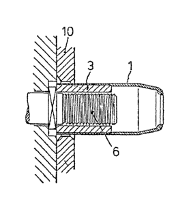
The structural details and the procedure of wheel mounting
according to the invention are apparent from Figs. 5 to 7:
For mounting a single wheel or an inner wheel 10, at first
the sleeves 1 with insert 3 are slipped onto the wheel
bolts 6 as can be seen from Fig. 5, and the wheel 10, as
has already been described above, is slipped on by means
of the mounting lever 2. Thereupon the wheel is fixed by
-- 5 --
~ 3 1 ~
means of wheel llUtS or by means of inner nuts 5, the
sleeves with their inserts 3 are removed and the remaining
wheel bolts that now become free are provided with the
remaining inner nuts 5.
Now the outer wheel 11 is slipped onto the outer threads
of the inner nuts 5 in analogous manner, by using the
sleeves 1 without inserts. Now the outer wheel 11 is also
being fixed by means of outer nuts 25, whereupon the
sleeves 1 are removed and the remaining outer nuts 25 are
screwed tight in their place, as becomes apparent from
Fig. 7. Sequence and tightening-torque when tightening, as
well as a periodical re-tigntening of the nuts 5, 25 must
be effected each in accordance with the safety regulations
of the motor vehicle or wheel producer.
,.
Dismounting of the wheels is effected simply in the oppo-
site order of the above-listed measures.
An advantage of using the arrangement according to the
invention is the absolute thread protection of all wheel
fastening threads, which is also indicated for reasons of
traffic safety, since only such the tightening torque
required can be compli~d with and excessive tightening of
the wheel nuts frequently occurring in practice can be
avoided.
The invention is not limited to the exemplary embodiment
illustrated according to Fig. 4. Basically, the invention
-- 6 --
~ i3~
also includes the idea of providing sucll a mounting sleeve
- be it one having ~he conically tapering shoulder illus-
trated, be it one having the cylindrical shape hitherto
common - with a detachable insert, wherein the insert may
serve for adjustment to the most varying wheel bolt diame-
ters. At its inner side the sleeve 1 may be provided with
a friction-increasing coating or other friction-increasing
provisions.
The same also holds true for the inner side and the outer
side of the insert 3.
A further characteristic of the invention is the conical
design of the end 7 of the sleeve 1. Thus also with larger
~olt thread and sleeve diam~rs it is possible to use the
mounting levers hitherto common, which is material and
weight saving.
The retracted diameter of the rim 8 follows upon the
constant diameter cam 12 of the mounting lever 2 in the
working position. According to a further characteristic of
the invention, the constant diameter cam 12 has a shoulder
13 that is substantially perpendicular to the longitudinal
axis of the mounting lever 2. The side face 17 of the
shoulder 13 facing the mounting lever 2 forms an edge with
the front torus face of the constant diameter cam 12.
As also illustrated - particularly in Fig. 8 - the front
face 19 of the mounting lever 2 is grooved, the groove 26
verging into the conically designed neck portion 18 that
in turn carries the constant diameter cam 12.
-- 7
1 3 ~ 9
Figs. 9 to 11 illustrate various positions of the mounting
lever 2 in relation to the sleeve 1. As already said
above, the sleeve 1 is located on a wheel bolt during the
mounting procedure, which wheel bolt is not illustrated in
Figs. 9 to 11. Fig. 9 shows the starting position,
substantially corresponding to Fig. 1. Thereupon the lever
2 is lifted in the direction of arrow 24 in Fig. 1, re-
sulting in a position according to Fig. 10, in which the
wheel can be slipped onto the sleeves and thus over all
the wheel bolts. For aiding this slipping-on-movement it
often is necessary to further lift the mounting lever 2
such that it also gets into positions illustrated in Fig.
11. At that further upward-pivoting of the mounting lever
2, the rim 8 of the sleeve 1 slides by at the wall of the
groove 26 without being hampered, the mounting procedure
thus not being impaired by any possible wedging between
mounting lever 2 and sleeve 1. With the mounting levers
hitherto known, there was a danger in this position (Fig.
11) of the constant diameter cam 12 becoming disengaged
with the sleeve 1. Particularly with sleeves having a
conically tapering end 7 this may possibly result in a
sliding off of the wheel that has not yet been completely
slipped on, so that the mounting procedure must be re-
peated. Furthermore there is the danger that a sliding-off
wheel may injure the person mounting it. These dangers arP
prevented by the shoulder according to the invention. As
clearly illustrated in Fig. 11, in this uppermost pivot
position, the shoulder 13 is form-lockingly or force-
lockingly supported by the bead 9 of the sleeve 1. The
-- 8 --
1 3 ~
mounting lever 2 cannot be further pivoted upwards, and a
disengagement between the constant diameter cam 12 and the
sleeve 1 has become impossible.
In an analogous manner, this holds also true for the
lowermost pivot end position of the mounting lever 2, the
shoulder 13 preventing the mounting lever 2 from falling
off as soon as it i9 released by the person mounting the
wheelO With reference to Fig. 8 it can further be said
that the constant diameter cam 12 is delimited in a manner
known per se by torus faces, which are enveloping surfaces
of two circles having different radii but a common center,
the ratio of the radii 20, 21 being approximately 6.375 to
10.625.
It goes without saying that the shoulder 13 may also be
designed as a locking means in a form different from that
shown in Fig. 8. Fig. 12. thus shows an embodiment in
which these locking means are provided as a groove 14, a
snap ring or spring ring 15 possibly being inserted- in
this groove. According to Fig. 13, furrows 16 or also
elevated wrinklings are provided, in the same way acting
as locking means.
The invention is not restricted to the exemplary embodi-
ments illus~rated. The sleeve 1 may also have a bead-like
reinforcement at its narrowed rim 8 which serves for
stability purposes and furthermore guarantees an unre-
leasable engagement of the shoulder 13 of the constant
_ g _
~31~
diameter cam 12 in the outermost inclined position of the
mounting lever 2. The locking means could also be provided
by arranging a particularly rough workinq material at the
end of the constant diameter cam 12.
According to a further characteristic of the invention,
the shaft of the mounting lever 2 is curved in a region 22
near the conically expanded end. This facilitates the
mounting procedure with driven motor car axles having
outwardly arranged planetary gears. This detail is appar-
ent from Fig. 14: there, the housing 27 of the gear body
makes it impossible to lift the wheel substantially beyond
the center line of the axle. From the curvature and thus
the inclined position of the mounting lever 2 there re-
sults, however, in a known manner, a horizontal force
component 23 on the inclined plane that is suitable to
effect the sliding on of the wheel 10.
-- 10 --