Note: Descriptions are shown in the official language in which they were submitted.
1316J~O
90762-5/LEH/fs
APPARATUS AND METHOD FOR AVOIDING CIRCUM~ENTION OF
AN IDENTITY CONFIRMING BREATH TESTER
Field of the Invention
The present invention relates to breath sobriety
testing. More particularly, the invention relates to an
apparatus and method for avoiding circumvention of a
breath sobriety tester such as the type which can be used
in a breath sobriety interlock system connectable to a
vehicle or other machine and normally operating to disable
the vehicle from starting unless a breath sobriety test is
passed by a person whose identity is confirmed by the
system.
Backaround of the Invention
The operation of vehicles by persons under the
influence of alcohol is a major safety problem in the
United States and many other countries. Despite growing
public awareness and government concern,
13~J~
-2-
statistics continue to show that a high percentage of
automobile accidents causing serious injury or death
involve drivers who have been drinking alcoholic
beverages in excess. Injuries in the workplace are
also often found to be related to the operation of
heavy equipment or other machinery by persons impaired
by the effects of alcohol.
To address ~his problem, various attempts
have been made to develop devices intended to prevent
automobiles and the like from being operated by
inebriated individuals. Such devices, which are
commonly referred to as "sobriety interlocks" are
often based on the well known principle that the gas
present in the alveoli of the lungs has an alcohol
content directly proportional to that of the blood
stream~ Blood alcohol content (BAC) thus can be
accurately determined by breath testing~ A sobriety
interlock is connected to the vehicle and normally
operates to prevent the vehicle from being started
unless one or more prerequisite conditions imposed by
the interlock are satisfied. Foremost among such
conditions is that any alcohol detected be present in
a sufficiently low concentration although, the inter-
lock may normally require any number of further
conditions to be met before starting of the vehicle is
enabled.
~ 3 ~
-3-
For example, it is generally acknowledged
that to accurately determine BAC from a breath sample,
an interlock must be designed to require delivery of a
"deep lung" breath sampleO As used herein and in the
claims, that term refers to a breath sample consisting
of a proportion of alveolar gas sufficient to permit
an accurate determination of blood alcohol concentra-
tion. Since breath expired from upper portions of the
respiratory tract does not nece~sarily have an alcohol
level proportional to that of the bloodstream~ a deep
lung sample is essential if an interlock is not to be
defeated by shallow exhalations of a series of short
puffs of brea~h expelled from upper portions of the
respiratory tract.
This problem is addressed effectively in
U.S. Patent Nos. 4,093,945 and 3,764,270 issued to
Collier et al. The Collier et al. patents disclose
means, such as a pressure switch and timer system, to
ensure delivery of an essentially continuous and
uninterrupted flow of breath sufficient to yield a
deep lung sample. The sampling interval determined by
the timer and the flow rate (a measured by the
pressure sensor or other flow sensing means) are
selected together to ensure a deep lung sample will be
given. Unless breath is delivered at at least a
minimum predetermined flow rate without interruption
for the entire sampling interval, a required condi~ion
.: .
~3~3$~
--4--
is not deemed satisfied and the vehicle cannot be
started~
Unlike breath analyzer tests which are
usually administered under the supervision of police
or other trained persons, sobriety interlocks are
routinely used outside the presence of persons other
than the vehicle operator/test subject whose use of
the interlock may be less than completely voluntary.
One example of such a situation is whexe an employer
seeks liability protection by installing interlocks on
vehicles operated by employees~ A higher degree of
compulsion may be involved in some cases of court-
supervised rehabilitation of offenders found to have
been driving while under the influence of alcohol
(DUI). As a mandatory condition for permitting a DUI
offender to drive in order to maintain employment
and/or obtain counselling, some courts may require a
sobriety interlock to be installed in the offenderls
car. In such cases there is an increased likelihood
that attempts to defeat the interlock will be made.
Accordingly, the prior art has proposed various
self-supervisory techniques directed toward avoiding
circumvention of interlocks by various forms of
subterfuge. These techniques typically share a common
characteristic in that they require one or more
additional conditions, usually unrelated to alcohol to
be satiqfied as prerequisites to s~arting the vehicle.
J
--5--
For example, techniques to discriminate
between a contemporaneous breath sample and bogus
gasses such air from a bicycle pump, filling station
air hose or breath from a previously inflated balloon
are discussed in U.S. Patenk Nos~ 4,592,443;
3,831,707; and 3,824,537. Each of these patents
proposes requiring one or more additional conditions
be satisfied before permitting the vehicle to start.
U.S. Patent No. 4,592,443 requires the temperature of
the gas deliv~red for a test to fall within a range
expected for breath. Breath being moist, U.S. Patent
No. 3,831,707 requires the gas to contain appropriate
humidity to avoid circumven~ing an interlock with a
bogus sas that is drier than breath. U.S. Patent No.
3,824,537 teaches requiring the operator to place one
hand on a button which must be activated during a test
period while the other hand is used to hold a breath
sampling tube located some distance away from the
button. Since both hands of the operator are placed
apart, deceptive manipulation of a bellows or the like
is discouraged. While all of these techniques have
some merit, they are of little overall benefit if a
sobriety interlock can be circumvented regardless of
them by the simple artifice of enlisting the aid of a
sober accomplice to take the test. Thi~ vexing
problem is dealt with in U.S. Patent No. 4,738,333 to
Collier et al.
~5-
..... ,~ ,
'
. . ' ' . .
~6--
The technique proposed in the above '333
patent is to require the operator/test subject to
identify himself or herself by correctly performing
what is termed an "identity-confirming act" which the
interlock is capable of recognizing. Unless this act
is correctly performed within a limited number of
attempts, the interlock will not penmit the vehicle to
be started regardless of the result of any alcohol
breath test. Unlike a personal identification number
(PIN) code which can be readily entered by another
person who is merely given knowledge of the code,
correct performance of the identity-conirming act
requires a degree of skill which cannot ordinarily be
acquired by most persons without attempting the act at
least some minimum number of times. The limited
number of attempts the interlock allows the act to be
tried is selected to be lower than the minimum number
of attempts ordinarily required to learn the act. In
this way, the interlock can effectively discriminate
between a trained designated person and a previously
unskilled accomplice. Where a sobriety interlock
includes such identification means, both the alcohol
measuring phase and the identification phases of the
test must be passed as prerequisites to enable
starting of a vehicle or other equipment connected to
the in~erlock.
~3~ ~$~
One emb3diment of the invention which is
specifically described in the abo~e-refere~ced '333
patent requires placing the mouth or lips over the
breath sample delivery port of the system in order to
S deliver breath thereinto in a predefined manner to
perform the identity-confirming act. By requiring use
of the same physical location as that which is
employed to deliver a breath sample for breath alcohol
analysis to perform the identity-confirming act,
in~reased assurance that these two acts will not be
performed by different pexsons i8 provided. Further,
tha system can require either a very short ~ime delay
or no delay at all be~ween breath sample delivary and
the identity confirming act thus making it highly
unlikely that two different persons could act quickly
enoush to deliver the breath sample and perform the
ident~ty confirming act. Even with such precaut~ons
it is desirable to even more positively ensure that
the identity confirminq act is performed by the same
individual who delivers the breath ~ample.
Additionally, thexe are other forms of
breath test apparatus in which users identity is
determined from an act performed by the user by
breathing or speaking into the mouthpiece of the
breath tester, such as in the use of sobriety breath
test apparatus employed with remote confinement or
"home arrest~ systems.
J ~ ~
Accordingly, there exists a need to increase the
assurance that a breath sample has not been delivered by
artificial means or by one other than-the identified operator of
a sobriety interlock, particularly interlock systems of the type
disclosed in U.S~ patent 4,738,333.
Summary of the Invention
According to the present invention, there is provided
a sobriety breath test apparatus, comprising: sampling means for
receiving exhaled breath from a test subject, said sampling means
including an alcohol sensor for generating an electrical signal
related to the level of alcohol in the breath; identify
confirming means connected to said sampling means for confirming
the identity of the test subject in accordance with the ability
of the test subject to perform an identity-confirming act, said
act requiring the delivery of breath into said sampling means;
means for reading said electrical signal to produce a first
reading related the level of alcohol in a breath sample received
by said sampling means and a second reading reflecting the
response of said sensor to breath delivered to said sampling
means during an attempt to perform said identity-confirming act,
and means for comparing said first and second readings and
generating a test fail signal in the event said second reading
diffexs from said first reading by more than a predetermined
amount.
According to another aspect of the present invention,
there is provided a method of avoiding circumvention of a breath
-- 8 --
~3~ 3~$~
sobriety tester of the type having an alcohol sensor operable
to generate an electrical signal related to the amount of alcohol
present in breath to which the sensor is exposed, said method
comprising the steps of: délivering a first sample of exhaled
breath to the alcohol sensor; taking a first reading of the
electrical signal generated by the alcohol sensor in response to
said breath sample; monltoring an attempt to perform an identity~
confirming act in order to conEirm the identity of a test subject
in accordance with the ability of the test subject to perform
said act, said act requiring delivery of a second breath sample
to the sensor; taking a second reading of the electrical signal
generated by the alcohol sensor in response to said second breath
sample, and generating a test fail signal in the event said
second reading differs from said first reading by more than a
predetermined amount.
Brief Description of the Drawings
Fig. 1 is a pictorial view of one preferred embodiment
of a sobriety interlock embodying the present invan-tion.
Fig. 2 is an electrical block diagram showing the
sobriety interlock of Fig~ 1 together with a wiring harness for
connecting the interlock to a _
~ 3 ~
--10--
vehicle electrical system and illustrating the con-
nec~ion of the interlock to first and second remote
service devices.
Fig. 3 is an electrical diagram showing
further details of the vehicle interface depicted in
block form in Fig. 2 and illustrating its connection
to a portion of a vehicle electrical system.
Fig. 4 is an electrical diagram showing
further details of the power supply depicted in block
form in Fig. 2.
Fig. S is an electrical diagram showing
further details of the microprocessor con~roller
depicted in block form in Fig. 2.
Fig. 6 is an electrical diagram showing
further details of the remote interface depicted in
block form in Fig. 2.
Fig. 7 is an electrical diagram showing
further details of the non-volatile memory depicted in
block form in Fig. 2.
Fig. 8 is an electrical diagram showing
further details of the heater control/analog interface
depicted in block form in Fig. 2.
Fig, 9 is an electrical diagram showing
further details of the fiampling head depicted in block
form in Fig. 2.
Fig. 10 is an electrical diagram showing
further details of the operator interface depicted in
block form in Fig. 2.
--10--
~ 3 ~
--11~
Fig. 11 is an electrical diagram showing
further details of the audio output depicted in block
form in Fig. 2.
Fig. 12 is an electrical block diagram
showing further details of the second remote service
device shown in Fig. 2.
Figs. 13A-13F are a series of flowcharts
illustrating the operation of the second remote
interface device of Fig. 12 wherein:
Fig. 13A illustrates the BOOT UP state;
Fig. 13B illustrates the READTIME state;
Fig. 13C illustrates the SETTIME s~ate;
Fig. 13D illustrates the READBYP state;
Fig. 13E illustrates the RESETT state; and
Fig. 13F illustrates the CONERR, COMMERR and
RSTERR error subroutines.
Fig. 14 is a software state diagram illus-
trating the operation of the microprocessor controller
of Fig. 2.
2Q Fig. 15 is a diagram illustrating the BOOT
UP state.
Fig. 16 is a diagram illustrating the PURGE
state.
Fig. 17 is a diagram illustrating the READY
state.
Fig. 18 is a diagram illustrating ~he BLOW
state.
-12- ~ 3 1 6 v ~ ~
Fig. l9A and Fig. l9B are diagrams which
together illustrate the ID state.
Fig. 20 is a diagram illustrating the
DISPLAY state.
Fig. 2lA and Fig. 2lB are diagrams which
together illustrate the RUN state.
Fig. 22 is a diagram illustrating the
STANDBY state.
Fig. 23 is a diagram illustrating the
SERVICE REMINDER LOCKOUT state.
Fig. 24 is a diagram illustrating the
DEMERIT LOCKOUT state.
Fig. 25 is a diagram illustrating the Sl
state.
FigO 26 is a diagram illustrating the S2
state.
Fig. 27 is a diagram illustrating the
BACKGROUND routine.
Fig. 28 is a diagram illustrating the
DISPLAYFAULT subroutine and the REMIND subroutine.
Fig. 29 is a diagram illustrating the CHKBYP
subroutine.
Fig. 30 is a diagram illustrating the INCDMT
subroutine.
Fig. 31 is a diagram illustrating the
CHKSUPPLY subroutlne.
-12-
~1 3 ~
-13-
Fig. 32 is a diagram illustrating the
CHKCONNECT subroutine.
Fig. 33 is a diagram illustrating the
CHKSTABLE subroutine.
Detailed DescriE~ion of the Preferred Embodiment
SOBRIETY INTERLOCK HARDWARE
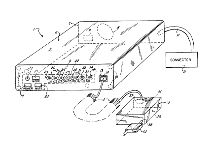
Referring initially to FigO 1, a sobriety
interlock 1 embodying the present invention includes a
control module 2 and a remote sampling head 3 con
nected thereto by way of a coilably retractable cable
4. Control module 2 is contained wi~hin a housing 5
having mutually opposed front and rear panels, 6 and
7, respectively. Rear panel 7 carries an audio beeper
8 and a miniature, six pin, female receptacle 9. A
multiple con~uctor wiring pigtail 10 terminated with
half of a locking male-female connector 11 exits rear
panel 7 to facilitate connection of control module 2
to a vehicle electrical system in a manner to be more
fully explained with reference to Figs. 2 and 3.
The front panel 6 of control module 2
carries an eight pin, miniature female recepta(.le 13
which mates with a detachable male plug 14, one of
which is affixed to each end of cable 4. Front panel
6 also carries the externally accessible portions of
an operator interface 15. The internal components of
control module 2 are secured within housing 5 by a
plurality of fasteners 16 the heads of which are
-.,- : ~, j ;,
`~ ~3~ $~
gO762-5/LEH/f s
concealed beneath an overlay 17. Overlay 17 is imprinted
with appropriate indicia as shown and, for security
purposes, is of a material such as a thin sheet of
polycarbonate backed with a strong, pressure sensitive
adhesive so that overlay 17 shows visible signs of
tampering if removal of it or fasteners 16 is attempted.
A similar overlay (not shown) is provided on the surface
of rear panel 7 covering fasteners there (also not shown).
That portion of operator interface 15 accessible
by way of front panel 6 includes three push buttons l9, 20
and 21 designated POWER, MUTE and MODE respectively, as
well as a bar graph style LED display 22 and a red
indicator LED 23. Bar graph display 22 includes a series
of ten colored LEDs numbered consecutively from 25 through
34 as viewed from left to right in Fig. l. These consist
respectively of; first and second GREEN LEDs ( 25, 26),
first, second and third YELLOW LEDS ( 27, 28, 29) and
first, second, -third, fourth and fifth RED LEDs (30, 31,
32, 33, 34)-
Sampling head 3 is detachably connected to cable
4 by way oE a second, eight pin miniature female
receptacle 37 which receives one of the male plugs 14
terminating cable 4. The structure and operation of
sampling head 3 are described in further detail herein
with reference to Figs. 1 and 9. For the present, it is
sufficient to note that sampling head 3 includes a housing
- 14 -
`/` `
. . , ~ , .
~ 3 ~ 39 07 62-5/LEH/fs
38 having a breath inlet port 39 into which a breath
sample can be delivered by way of a dlsposable mouthpiece
40- A green colored READY LED 41 iS visible externally of
housing 38. When interlock 1 is prepared to receive a
breath sample, READY LED 41 flashes. While a breath
sample is in the process of being delivered at a
sufficient flow rate, READY LED 41 stops flashing and
remains lighted.
Referring now to Fig. 2 there is shown an
electrical block diagram wherein the confines of the
housing 5 enveloping control module 2 are indicated in
broken lines. It can be seen from Fig. 2 that control
module 2 includes a vehicle interface 45, a power supply
46, a remote interface 47, a non-volatile memory 48, an
analog and a heater control 49, operator interface 15 (a
portion of which has already been described) as well as an
audio output 50; each of which is connected via one or
more lines to a microprocessor controller 51.
Control module 2 also includes provisions for a
2Q number of external connections. These include connections
to sampling head 3 as well as the vehicle electrical
system. ~s prev i ous l ~
;'`~ 15
.,
~ 3 ~
-~6-
3 is connected to control module 2 via cable 4 and the
male plugs 14 which terminate it. The connPctions
between the vehicle and vehicle interface 45 are made
by way of pigtail 10 and a wiring harness 58 which
includes a connector 59 that mates with the connector
11 termina~ing pigtail 10. As shown, pigtail 10
includes separate red, black, green, white and orange
wires labellPd respectively as lOa-lOe as well as a
pair of blue wires labelled lOf and lOg. Wiring
harness 58 includes a set of correspondingly colored
wires 58a~58g the connections of which to the vehicle
will be described later with reference to Fig. 3.
Also, in place of sampling head 3, the female recepta-
cle 13 mounted on the front panel 6 of control module
2 can be connected to a first remote service device 55
while remote interface ~7 is adapted to communicate
via receptacle 9 with a second remote service device
56. Remote service devices 55 and 56 will also be
explained in further detail later.
With continuing reference to Fig. 2 the
principal internal connections of control module 2
will now be summarized. Vehicle interface 45 conducts
lines lOa, lOb and lOc directly to power supply 46 to
supply it with electrical power from the vehicle. As
will be explained further in connection with Fig. 4,
power supply 46 defines three power supplies desig-
nated V~NO~E ~1~ VMAIN 62 and Vsw 63. VANODE 61
16-
3 ~
-17-
monitored by controller 51 by way of analog interface
49 while vMAIN 62 powers at least a portion of each of
circuits 15, 45, 47, 48, 49 and 51. Vsw 63 is a power
supply that i5 switched under the control of a PDC
line 52 from controller 51 in order to allow interlock
1 to operate in a low power drain or "standby" state
to conserve the battery of the vehicle especially
during prolonged periods of non-use. For that reason,
Vsw 63 supplies power to audio output 50/ sampling
head 3 (via heater control/analog interface 49) and to
a portion of vehicle interface 45. Power supply 46
also includes an interlock chassis connection 66 and
ground 67. The ground 67 is connected to each of the
circuits 15, 45, 47, 48, 49, 50 and 51. To minimize
noise, the ground 67 associated with the analog
circuits should be run separately from those associ-
ated with digital components. The operation of beeper
8 is controlled by way of a line AOC 65 connected
between controller 51 and audio output circuit 50 as
will later be explained in further detail with refer-
ence to Fig. 11.
Vehicle in~erface 45 is connected to con-
troller Sl by way of lines designated ILK 68, HRN 69
and IGN 70. ILK line 68 is controlled by controller
51 in order to selectively enable and disable starting
of the vehicle. The HRN line 69 is used to allow
controller 51 to sound the horn of ~he vehicle while
-17~
1 3 ~
-18-
IGN line 70 is used for two purposes. In the first
in~tance, it allows controller 51 to sense whether the
vehicle ignition switch is off or in its RUN position.
When interlock 1 is not in operation and is being
serviced, line IGN 70 is used as a communication line
between second remote service device 56 and controller
51 via remote interface 47. As will later be elab-
orated upon, such communications are further facil-
itated by three lines; RST 73, SRS 74 and SCL 75 which
lQ are connected between controller 51 and remote inter-
face 47. RST line 73 is also connected to power
supply 46 to permit resetting of controller 51 in the
event a low voltage condition occurs.
As will be explained further with reference
to Fig. 10, operator interface 15 is connected to
controller 51 by way of lines designated MTE 76, PWR
77 and MDE 78 emanating, respectively, from push
buttons 20, 19 and 21 while a line designated IND 79
connects controller 51 with LED indicator 23 and a
series of lines BG0 through BG9 80 through 89 (Fig.
5~, respectively connect controller 51 with each
respective LED 25 through 34 making up bar graph
display 22. It will be noted that line BGP 80 is also
used by controller 51 to transfer data to non-volatile
memory 48 (i.e., write to memory) while a line EDO 92
is used to transfer data in the reverse direction from
memory 48 to controller 51 (i.e., read from memory).
-18-
~ 3 ~
--19--
These functions are assisted by lines ECS 93 and AD6
94 which are used respectively as chip select and
clock lines for memory 48. Line AD6 94 is also used
as a clock line for the analog interface portion of
circuit 49. Heater control/analog interface circuit
49 also includes a number of other connections to
controller 51. These include lines AD1 96, AD2 97,
AD4 98, AD5 99 and HTC 100.
Sampling head 3 is connected to controller
51 by way of cable 4 which includes lines RDY 101 and
PSW 102 and is connected to heater control/analog
interface 49 by way of lines; SEN 103, FBX 104, HTR1
105 and HTR2 106 as w811 as connections to power
supply Vsw 63 and ground 67. These lines will be
discussed in further detail with particular reference
to Figs. 5, 8 and 9.
Vehicle Interface
Referring additionally now to Fig. 3,
vehicle interface 45 and its connections to portions
of a ~ehicle electrical system 115 are illustrated in
further detail with components of vehicle electrical
system 115 being shown in broken lines. Wiring
pigtail 10, which carries connector 11 on one end,
terminates at its opposite end on a printed circuit
board 107 upon which each of: vehicle interface 45,
power supply 46, remote interface 47, audio output 50,
non-volatile memory 48, controller 51 and heatar
--19--
-20- ~3~
control/analog interface 49 are all at least par~ially
carried. Connector 11 mates with connector 59 of
wiring harness 58 which is wired to components of
vehicle electrical system 115 in the manner shown. In
particular, electrical system 115 includes a battery
108 whose positive terminal 109 is wired to line 58a
and whose negative terminal 110 is wired to line 58b
as well as wire 58c which is connected to both the
chassis 111 of the vehicle the ground side 112 of the
vehicle starter solenoid 113. The opposite siae 114
of solenoid 113 is connected to wire 58g. The posi-
tive terminal 109 of battery 108 is also connected ~o
the line side 116 of the vehicle horn relay coil 117
as well as two pairs of contacts 119, 120 associated
the vehicle ignition switch. Contacts ll9 comprise a
set of normally open contacts that are maintained
closed when the vehicle ignition switch is in a RUN
position. Contacts 120 are normally open contacts
that are momentarily closed while the vehicle ignition
switch is held in a STA~T position as it is when
attempting to start the vehicle. As can be seen, the
load side of contact~ 119 are wired to line 58d. IGN
line 70 is formed by connection of line lOd to a
voltage divider made up of resistors 122 and 123 the
output of ~he voltage divider being clipped by a Zener
diode 124 to limit the maximum voltage appearing on
line IGN 70 in accordance with the rating of diode
-20
J ~ ~
-21-
124~ Thus, the voltage appearing on line IGN 70 can
be sensed directly by controller 51 to determine
whether or not the vehicle ignition switch contacts
are in their R~N position.
To control the horn (not shown) of the
vehicle, line lOe, which is connected to horn relay
coil 117 through wire 58e, is selectively pulled low
by transistor 126 the drain of which i8 connected to
line lOe and also ultimately to the positive terminal
109 of battery 108 by way of line lOa through a
transient suppressing diode 127. Transistor 12Ç is
itself controlled by controller 51 according to the
signal appearing on HRN line 69 which is applied to
the base of a bipolar NPN driving transistor 128
through a series resistor 125. The collector of
transistor 128 is connected to the gate of transistor
126 such that when controller 51 pulls HRN line 69
low, transistor 128 is cut off and its collector is
pulled up by a resistor 129 which connects the collec
tor of transistor 128 to supply Vsw 63. This causes
transistor 126 to conduct thereby completing the
circuit from coil 117 to ground in order to cause the
horn to sound. It is noted that transistor 128 is
supplied from switched power supply Vsw 63. Thus,
sounding Qf the vehicle horn is disabled whenever
controller 51 causes power supply Vsw 63 to be turned
off in order to conserve battery 108. ~o ensure that
-21-
-
1 3 ~ ~J~
-22-
the vehicle horn does not sound during power up of
interlock 1, a pullup resistor 121 is connected
between HRN line 69 and the VMAIN power supply 62. It
should be noted that the vehicle horn can still be
operated manually by way of the vehicle horn button
(not shown) for signaling by the operator~ However,
HRN line 69 can overxide the vehicle horn button so
that the horn can be sounded under the control o~
controller 51 regardless of whether the horn button is
pressed by the operator. As will be seen, this
capability is used in the event an operator fails to
take a timely retest in the event one is required.
Starting of the vehicle is selectively
enabled and disabled under the control of controller
51 by way of line ILK 68 which is connected by way of
a resistor 133 to the base of a Darlington transistor
130 whose collector is coupled to the coil of an
ignition interlock relay 131 that is shunted with a
protective diode 132. Relay 131 has a normally open
contact connected in series with vehicle ignition
switch contacts 120 by way of wires 58f and lOf as
well as with the non-grounded side 114 of ignition
solenoid 113. Thus, starting of the vehicle is
enabled when ILK line 68 is pulled low by controller
51 thereby causing transistor 130 to conduct which
energizes xelay 131 causing its contact to close so
that the vehicle operator can start the vehicle by
-22-
-23-
applying power from battery 108 to solenoid 113
through ignition switch contacts 120.
Power SuPply
With additional reference now to Fig. 4
power supply 46 will now be described in further
detail. The positive and negative terminals 109, 110
of battery 108 are connected by way of lines 10a and
10b to a filter network 134 which includes series
inductors 135 and 136 and parallel capacitors 137 and
138 which are connected together at a node linked to
line 10c as shown. The line side of inductor 136 is
connected to the chassis ground point 66 of control
module 2 while its load side defines ground 67.
Overcurrent protection is provided by a fuse Fl 139
connected in series with line 10a while overvoltage
protection is provided by a varistor 140 connected
across the lines 10a, 10b spanned by capacitors 137
and 138. A reverse current blocking diode 144 is
connected in series with the output side of filter
2Q network 134 to prevent damage to the circuitry of
control module 2 in the event the polarities lines 58a
and 58b (Fig. 3) are reversed. The anode of diode 144
defines a filtered but unregulated power supply VANODE
61 while its cathode defines node VIN 64. A five volt
voltage regulator 145 has its input connected ~o node
VIN 64 which is spanned by a capacitor 148. The
output of regulator 145 define~ regulated ~5 volt
1 3 ~ ~ ~ J~
-24-
power supply VMAIN 62 which is spanned hy a capacitor
149. Voltage regulator 145 is preferably a type such
as an LM2925 manufactured by National Semiconductor
which includes a reset pin which can be connected to
controller 51 by way of RST line 73 as indicated. In
the even~ regulatox 145 cannot maintain its nominal
output voltage, requlator 145 pulls line RST 73 low in
order to effact a hardware reset of the microprocessor
associated with controller 51. A re~istor 150 and
capacitor 151 are connected to RST line 73 as shown in
order to dampen any oscillations which might otherwise
occur thereon. A 0~1 microfarad capacitor 1S2 is con-
nected between pin 4 of regulator 145 and ground in
order to determine the duration of the reset signal.
Switched 12 volt power supply Vsw 63 is
developed by connecting node VIn 64 to the source of a
field-effect transistor (FET) 153 the drain of which
defines supply Vsw 63 and the gate of which is con-
nected to the collector of a driving transistor 154
that is connected to VIN 64 by way of a resistor 155.
The emitter of transistor 154 is connec~ed to ground
67. The base of transistor 154 is connected to PDC
line 52 through a resistor 156. Thus V5W 63 is turned
off whenever controller 51 pulls PDC line 52 low.
This cuts off transis~or 154 so that resistor 155
pulls its collector high thereby cutting off
-24-
~ 3 ~
-25-
transistor 153 to deenergize supply Vsw 63. Converse-
ly, when PDC line 52 is high, supply Vsw 63 is turned
on.
Microprocessor Controller and O~ ator Interface
With reference to Figs. 5 and 10 controller
51 and operator interface 15 will now be explained in
further de~ail. Controller 51 includes a programmable
microprocessor 160 which may suitably comprise a type
such as a part number HD637B05VOP manufactured by
Hitachi America, Ltd. which is configured as a single
integrated circuit having pins numbered consecutively
from pin 1 to pin 40. As shown in Fig. 5, micropro-
cessor 160 is supplied power from VM~IN 62 by way of
pin #40 r which is shunted to ground 67 by way of a
capacitor 161, as well as by way of pin #3 which is
tied directly to ground 67 as are pin #37 and pin #20.
A conventional 4.000 M~z time base 162 is connected
across pin #38 and pin #39. To effect a hardware
reset of microprocessor 160 by vol~age regulator 145
RST line 73 is connected to pin #1. Consecutive pin
numbers 29 through 35 of microprocessor 160 define I/O
port D and are connected respectively to lines: ILK
68, ECS 93, IGN 70, PDC 52, SRS 74, AOC 65 and SCL 75.
These are configured as microprocessor inputs or
outputs as indicated by arrows in Fig. 5. The func-
tions of lines ILK 68, IGN 70 and PDC 52 have already
been explained. ~he functions of lines SRS 74 and SCL
-25
~.33.'~JI~
-26-
75 will be explained more clearly with reference to
Figs. 6, 12 and 13 while those of lines ECS 93 and AOC
65 will be clarified in connection with the descrip-
tions of Figs. 7 and ll respectively. Pin #36, which
is tied to VMAIN 62, is not used.
Each LED, 25 through 34 making up bar graph
display 22 is individually controlled by microproces-
sor 160 by way of lines BG0 80 through BG9 89. Those
lines are connected to microprocessor 160 by way of
microprocessor pin numbers 8 through 17 respectively.
Connection of lines BG0 80 through BG9 89 to corre
sponding LEDs 25-34 are made by way of male and female
connectors Jl 164 and J2 165 each having pins numbered
1 through lO. The male pins of connectors Jl, 164,
and J2, 165 are shown in Fig. 5 while the correspond-
ingly numbered female pins are depicted in Fig. lO.
(Note that Fig. 5 also shows pins 3 and 4 of eight pin
receptacle 13 the remaining pins of which are shown in
Fig. 8). As can be seen from Fig. lO, each of lines
BG0 80 through BG9 89 is connected to the cathode of
each respective LED 25 through 34 by way of one of a
series of buffers 167. One of the same buffers 167
similarly connects the cathode of indicator LED 23 to
pin 7 of microprocessor 160 by way of line IND 79.
The anode of LED 23 as well as those of LEDs 25-34 is
connected to power supply VMAIN 62 through one of a
series of resistors 168.
-26-
:~ 3 ~
-27-
Operator interface 15 is mounted on a
separate printed circuit board 170 from the printed
circuit board 107 carrying the remainder of the
electronics within control module 2. Circuit board
170 receives its power f~om supply vM~IN 62 by w~y of
pins 9 and 10 of connector J2 165 as well as pin 2 of
connector Jl 164. Circuit board 170 receives ground
67 by way of pins 1 and 10 of connector J1 164 as well
as pin 8 of connector J2 165.
The push buttons on front panel 6 designated
POWER l9, MUTE 20, and MODE 21 are each normally open,
momentary, single pole, single throw types and has its
line side connected to suppiy VMAIN 62 and load side
connected to lines PWR 77, MTE 76 and MDE 78 respec-
tively. Those lines are carxied to circuit board 170
from circuit board 107 through connector Jl 164 by way
of pins 4, 3 and 5 respectively as shown in Fig. 7.
For noîse immunity, the load side of each push button
19, 20, 21 is connected to ground 67 by way of a pull
down resistor 171. As can be seen from Fig. 5, lines
MTE 76, PWR 77 and MDE 78 are connec~ed, respectively
to pins 2, 5 and 6 of microprocessor 160. Those pins
axe configured as inputs whereby microprocessor 160
can sense the pressing of each push button 19, 20 and
21 by a person.
In addition to being us~d as outputs for
selectively lighting the LEDs 25~34 making up bar
-27-
~28- 13~ ~J ~ ~
graph display 22, lines BG0 80 through BG9 89 are also
momentarily used as inputs to microprocessor 160. As
will be no~ed in connection with the description of
the "BOOT UP" state in the software description which
appears later, these lines are also used to read the
status of a series of pairs of jumper posts (a through
j) which appear in Fig. 5 on a common header 173.
Each line BG0 80 through BG9 89 is connected to one
side of each respective pair of posts (a through j) as
well as to power supply VMAIN 62 by way of one of a
series of pull up resistors 174. The opposite side of
each pair of posts a through j on header 173 are
connected, through one of a series of diodes 175 to
pin 22 of microprocessor 160 by way of a strap select
line STS 176. To read which, if any, of the pairs
posts a through j may be shor~ed with jumper straps,
microprocessor 160 momentarily pulls STS line 176 low
and reads the logical state of each of lines BG0 80
through BG~ 89. If any of those lines reads low, it
indicates that the corresponding pair of posts is
jumperedO The presence or absence of a jumper strap
across each pair of jumper posts a through j on header
173 indicates to the microprocessor whether any of
several selectable features are to be implemented.
Among these features are the abili~y of
interlock 1 to require a pro~pective operator to
identify himself as being a particular individual.
-28-
~, .
`3
-29-
This is preferably accomplished by requiring the
operator/test subject to perform what shall be
referred to as an "identity-confirming act" which a
designated operator has previously been trained to
perform correc~ly and which microprocessor 160 is
programmed to recognize. Unless this act is correctly
performed within a limited number of attempts in a
given time, interlock 1 will not permit the vehicle to
be started for some period of time regardless of the
10 result of any alcohol breath test. The limited number
of attempts allowed is selected in accordance with the
degree of skill required to learn to perform the act
correctly such that a person cannot ordinarily learn
to perform the act in fewer than that number of
lS attempts. Thus, a previously untrained accomplice
will not likely be able to perform the act instead of
the designated trained operator in order to evade the
test. This technique has been described in detail in
commonly assigned U.S. Patent No. 4,738,333 issued
20 April 19, 1988 and will be assumed to be incorporated
in the sobriety interlock 1 being described. As will
be explained further with reference to Fig. 19, one
preferred embodiment of the identity-confirming act
consists of blowing a series of puffs or "bursts" of
breath interspaced with pauses into the mouthpiece 40
of sampling head 3 beginning just after the BAC
measurement phase o the test i~ completed. The puffs
-29-
~ 3 ~ i:3v ~
-30-
of breaths and pauses must conform to predetermined
timing requirements in order to pass this "ID phase"
of the test.
In addition to selecting whether sobriety
interlock 1 requires performing an identity-confirming
act as a precondition to starting the vehicle, strap-
able header 173 can also be used advantageously to
select other options such as alternate BAC levels at
which interlock 1 will provide a WARN indication
and/or enable vehicle starting and whethPr interlock 1
is to require periodic retesting after the vehicle is
started regardless of the results of previous breath
tests.
Returning now to consideration of the
structure and basic operation of controller 51, pin
#18 of microprocessor 160 is connected to PSW line 102
which extends to sampling head 3 by way of receptacle
13. PSW line 102 is tied to supply VMAIN 62 by way of
a pull up resistor 177 and is shunted to ground 67
through a capacitor 178. As will be further explained
in connection with Fig. 9, PSW line 102 i~ connected
to means for ~ensing whether breath is being delivered
to sampling head 3 at at least a predetermined minimum
flow rate. Accordingly, pin 18 of microprocessor 160
is configured as an input.
Ready LED 41 which is visible exteriorly of
sampling head 3 is qelectively lighted under the
-30-
control of micropxocessor 160 by way of pin ~19
thereof which is connected to RDY line 101. RDY line
101 is driven by a transistor 180 that is controlled
through a resistor 181 and supplies current to READY
5 LED 41 from supply VMAIN as shown through pin 4 of
connector 13.
The horn of the vehicle is controlled by
line HRN 69 in the manner previously described. That
line is connected to pin ~26 of microprocessor 160
whereas lines AD1 96, AD2 97, ~D4 98, AD5 99 and AD6
94 are connected to micropxocessor 160 at pin #28, pin
#27, pin #25, pin #24 and pin #23 respectively as
shown in Fig. 5. Those lines will be discussed
further somewhat later in relation to Fig. 8. Each of
the afoxementioned pins is configured as an output
except for pin #24 which serves as an input to micro-
processor 160.
Remote Inter ace
With additional reference now to Fig. 6, the
structure and basic operation of remote interface 47
will now be described. Remote interface 47 provides
means for effecting two way communications between
interlock 1 and a second remote service device 56.
For this purpose, remote service device 56 is con-
nectable to remote interface 47 by way of the femalereceptacle 9 mounted in the rear panel 7 of control
-31
~ 3 ~ $ ~ 8 ~
-32-
module 2. Receptacle 9 includes six pins which are
designated as 9a through 9f as sho~n.
Communications from remote service device 56
to the microprocessor 160 of interloc~ 1 are carried
by way of pin 9a through a resistor 184 to IGN line 70
which is connected to microprocessor 160 at pin #31
thereof. It should be noted here that remote service
device 56 is to be used only by trained, authorized
personnel during initial ins~allation or servicing of
interlock 1 and at times when the vehicle to which
interlock 1 is connected is not running so that IGN
line 70 can carry serial digital communications
signals~ As can be appreciated from the description
of vehicle interface 45 provided earlier, IGN line 70
could not be used for communications when the vehicle
is running since IGN line 70 is always at a logical
high level when vehicle key switch contacts 119 are in
their RUN position.
Communication in the opposite direction,
that is, from microprocessor 160 to the second remote
service device 56 take place by way of line SCL 75
which drives pin 9d of receptacle 9 by means of a
transistor 185 whose base is connected to SCL line 75
through a resistor 186. The collector of transistor
185 is connected directly to pin 9d of receptacle 9
and is also connected to power supply VMAIN 62 through
a resistor 187. The emitter of transis~or 186 is
-32-
~ 3 ~
-33~
connected to ground 67 which is carried to second
remote sexvice device 56 by means of pins 9c and 9e of
receptacle 9.
So that proper connection between second
remote service device 56 and microprocessor 160 can be
assured, microprocessor 160 generates a coded inter-
lock signature signal on line SRS 74. Tha~ lin0 is
connected to pin 9b of receptacle 9 by way of a
driving transistor 189 whose collector is connected
directly to pin 9b as well as to supply VMAIN 62
through a pull up resistor 190. The base of transis-
tor 189 is driven by line SRS 74 through a resistor
191. In order to permit second remote service device
56 to perform a hardware reset of microprocessor lÇ0,
pin 9f of receptacle 9 is connected through a resistor
192 to RST line 73.
Non-Volatile Memory
With additional reference now to Fig. 7,
non-volatile memory 48 will now be described in
further detail. Memory 48 includes a non-volatile
data storage device such as an electrically erasable,
programmable read-only memory (EEPROM) 195 which may
suitably comprise a part number HY93C46 manufactured
by Hyundai which is a serial device with a 64X16 bit
capacity. Memory 195 is supplied power by way of
V~AIN 62 and ground 67 with VMAIN 62 being connected
to ground 67 by way of a capacitor 196. Line ECS 93
-33-
- 1 3 ~ ~3~J~
-34-
emanating from microprocessor 160 at pin # 30 is used
as a chip select and is connected appropriately to the
CS (chip select) pin of memory 195 as well as to
ground 67 by way of a pull down resistor 197. Micro-
processor 160 drives ECS line 93 high whenever data isto be either written into ox read from memory 195.
Memory 195 is clocked by microprocessor 160 by way of
line AD6 94 at a pin designated SK which is also
linked to ground 67 by way of a pull down resistor
198. Data to be written from microprocessor 160 into
memory 195 is received serially at pin DI (data in)
thereof by way of line BG0 80. Similarly, data to be
read from memory 195 to microprocessor 160 is carried
by way of line ~DO 92 which is connected to pin DO
(data out) of memory 195. When inactive, line EDO
(92) is pulled up to supply VMAIN 62 by way of a
resistor R6 199 connected therebetween.
Samplin~ Head
With additional reference now to Fig. 9,
sampling head 3 will now be described in further
detail. Sampling head 3 is substantially enveloped
within a housing 38 through which READY LED 41 is
visible. Housing 38 captures female receptacle 37 the
pins of which are designated 37-1 through 37-8 con~ec-
utively. Pins 37-1 through 37-8 are connected to
eight correspondingly numbered pins 13-1 through 13-8
associated with the female receptacle 13 on the front
-34-
, :, ,
90762-5/LEH/fs
panel 6 of control module 2. These connections are made
by way of cable 4 each end of which carries a male
connector 14.
Sampling head 3 includes an alcohol sensor 200
which may suitably comprise one of any number of devices
capable of providing an electrical signal that varies
predictably with the amount of alcohol to which it is
exposed. One suitable type of alcohol sensor is the
semiconductor type whose electrical resistance decreases
predictably with the amount of alcohol adsorbed onto its
surface. Such a sensor 200 is incorporated, along with a
heater 202, in a sensor assembly 201. A suitable sensor
assembly 201 is made by Figaro Engineerlng, Inc. of Osaka,
Japan and is available commercially in the United States
as model TGS-813P from Figaro USA, Inc. of Wilmette,
Illinois. For present purposes it is sufficient to note
that sensor 200 lies in gaseous communication with breath
delivered into the inlet port 39 of sampling head 3 by way
of mouthpiece 40.
Alcohol sensor 200 has one leg connected to
ground 67 and a second leg connected to pin 37-6 by way of
a line FBK 104 which includes a calibration potentiometer
205. The node between potentiometer 205 and sensor 200
corresponds to the output of sensor 200 and is carried to
~5 pin 37-5 over SEN line 103. Heater 202 has its leads
- 35 -
-
~ 3 ~ 90762-5/LEH/fs
connected to pins 37-7 and 37-8 by way of lines designated
HTRl 105 and HTR2 106 as shown.
Sampling head 3 also includes means for sensing
breath flow. Pressure switch 208 includes a set of
normally open contacts one side of which is connected to
ground 67 the other side of which is connected to
microprocessor 160 by way of line PSW 102 and connected to
pin 37-3 of receptacle 37 (see also Fig~ 5). Although
other devices including solid state pressure switches or
various forms of flow sensors could be used for this
purpose a pressure switch 208 has been -found suitable.
One suitable pressure switch 208 is an electromechanical
type such as model PSF~lOOA04.0 manufactured by World
Magnetics of Traverse City, Michigan. For present
purposes, it is sufficient to note that the contacts of
pressure switch 208 are closed only when the flow of
breath delivered to sampling head 3 by an operator through
mouthpiece 40 meets or exceeds a desired minimum flow
rate. Pressure switch 208 closes to signal microprocessor
160
36 -
~ 3 ~ 6 ~
-37-
when the flow of breath delivered into inlet port 39
is at least equal to a predetermined minimum flow.
That flow is selected to be sufficient to ensure that
a "deep lung" breath sample is delivered to sensor 200
provided such flow or a larger flow is maintained
continuously wi~hout interruption for at least a
predetermined minimum time such as 4.5 seconds. As
used herein, the term "deep lung" refers to a breath
sample consisting of a proportion of alveolar air
sufficient to permit a suitably accurate determination
of blood alcohol content (BAC) from such a sample.
Pressure switch 208 also conveniently serveæ as a
means for sensing the flow of breath during the
various phases of the identity-confirming ac~ de-
scribed earlier.
Ready LED 41 is wired with its cathodeconnected to ground 67 while its anode is connected to
RDY line lO1 at pin 37-4 by way of a resistor 210.
Microprocessor 160 controls RDY line 101 such that
READY LED 41 flashes when interlock 1 is ready to
receive a breath sample. When sample delivery com-
mences as indicated by the closure of pressure switch
208, READY LED 41 stops flashing and remains steadily
lighted until a deep lung breath sample has been
received whereupon it is extinguished.
An auxiliary hea~er element 212 and a
thermistor 213 are included in sampling head 3 in
~ 3 ~
-3~
thermal communication with the flow path thxough which
breath passes. When thermistor 213 senses a suffi-
cien~ly cold temperature, element 212 is energized as
necessary to maintain a sufficient temperature to
prevent freezing of moisture in the breath sample. At
the same time element 212 tends to maintain the
regions adjacent sensor assembly 201 at a relatively
stable temperature of abou~ 21C in order to avoid an
excessively cold operating environment for sensor 200.
As shown in Fig. 9, thermistor 213 is
connected in series with 150 K resistor 215 and 8.2K
ohm resistor 216 across supply Vsw 63 and ground 67
which are carried from control module 2 by way of pins
37-1 and 37-2 respectively of receptacle 37 to form a
voltage divider at node VT. Thermistor 213 is a
negative thermal coefficient type such as part number
GB41M2 made by Fenwal Electronics Div. of Kidde, Inc.
of Framingham, Massachusetts. Node VT is connected by
way of a series 4.7K ohm resistor 217 to the nonin-
verting input of a first amplifier 218 which itself is
connected to ground by way of a 220K ohm resistor 219.
The inverting input of amplifier 218 is connected by
way of a series connected 4.7K resistor 220 ~o a
voltage divider formed by the series combination of
resistor 215 together with an 8.2K ohm resistor 221
and an 12K ohm resistor 222 as shown. A 220X ohm
feedback resistor 223 connects the inverting input of
-3~-
~,3~,~rL,~
-39-
amp ~18 with its output. Thus, amp 218 is conf igured
as a conventio~al balanced dif ferential amp which
amplifies the voltage difference appearing between
node VT and a reference voltage node defined by ~he
junction between resistors 221 and 222. That voltage
difference increases as the temperature sensed by
- thermistor 213 decreases. The base of a transistor
225 is connected to the output of amp 224 by way of a
3.3K ohm resistor 226 while the collector of transis-
tor 225 is connected to one end of element 212 whose
other side is connected ~o supply Vsw 63. A 1.5 ohm,
2 watt resistor 227 connects the emitter of transistor
225 to ground 67. The noninverting input of amp 224
is connected to the output of amp 218 while the
inverting input of amp 224 is connected across resis-
tor 227 to the emitter of 225 as a means of limiting
the current through element 212. A second transistor
228 such as an NPN type 2N3904 has its base connected
to the emitter of transistor 225, its collector to the
base of transistor 225 and its emitter to ground 67.
A Darlington transistor, 229 such as a type MPSA14, in
turn has its base connected to node VT, its emitter
grounded and its collector connected to the base
transistor 225. Normal operation of the circuit
controlling element 212 i5 as follows.
The voltage at node VT rises as the tempera-
ture sensed by thermistor 213 drops and is amplified
-39-
r~
-40-
by amp 21~ and upper end limited by amp 224 energizing
element 212 with the amount of powex required to
maintain the thermistor 213 at the temperature deter-
mined by resistor 215, 221 and 222. In the event
thermistor 213 should open circuit, VT is pulled up to
a voltage that is sufficiently high to turn transistor
229 on thereby pulling the base of transistor 225 to
ground 67. This prevents element 212 from being
powered. In the event element 212 shorts out, the
abnormally high current passing through the collector
of transistor 225 would develop a sufficient voltage
across resistor 227 to bring transistor 225 into a
conducting state, clamping the base of transistor 225
low and thereby limi~ing the power to element 212.
Energization of element 212 is thus independent of
microprocessor 160 except to the extent that element
212 can be deenergized by microprocessor 160 by
causing Vsw 63 to be turned off in the manner
described earlier. This occurs when microprocessor
160 operates in a state known as STANDBY in order to
conserve vehicle battery 108~
Heater Control/Analog Interface
With additional reference now to Fig. 8 as
well as Fig. 9 the circuitry for controlling the
heater control/analog interface circuit 49 will now be
described.
--~0--
r)
-41-
We turn initially to that portion of circuit
49 which relates to the control of the heater 202
associated with alcohol sensor assembly 201. Heater
202 is supplied power from an 8 volt regulator 232
which may suitably comprise a National Semiconductor
part number LM2930 having an input, VI connected to
supply V5W 63 across a capacitor 233 an output, VO
connected across a capacitor 234 as well as a ground
pin connected to ground 67. As previously noted,
control module 2 is connected to sampling head 3 by
way of correspondingly numbered pins of connectors 13
and 37 which are spanned by cable 13. Power supply
Vs~ 63 is carried on pins 13-1 and 37-1 while ground
67 is carried on pins 13-2 and 37-2. The regulated
output of regulator 232 is carried to one side of
heater 202 by way of pins 13-7 and 37-7, each of which
is connected to line HTRl 105. The opposite side of
heater 202 is connected by way of line ~TR2 106 and
pins 37-8 and 13-8 to the collector of a transistor
237 disposed in a heater control and sensing circuit
238.
Control of the average power applied to
heater 202 is effected by applying a variable duty
cycle signal to the base of transistor 237 by way of a
resistor 239. When transistor 237 is driven into
conduction line HTR2 106 is pulled low causing current
to flow through heater 202 whereas when 237 i
-41-
-42-
substantially cut off, heater 202 is deenergized. The
duty cycle of the signal appearing at the base of
transistor 237 is determined by microprocessor 160
which applies an appropriate variable duty cycle
signal to HTC line 100. HTC line 100 drives the base
of buffer transistor 240 which in turn drives transis-
tor 237. A pullup resistor 241 is connected between
the base of transistor 240 and supply ~MAIN 62 the
latter also being connec~ed to the collector of
transistor 240. It can be appreciated that as the
duty cycle of the signal generated on HTC line 100 by
microprocessor 160 varies so too does the average
power applied to heater 202. It should be noted that
whenever heater 202 is referred to herein as being
"on" or "energized" the voltage waveform applied to
heater 202 is a pulse train as opposed to a continuous
D.C. signal.
During alcohol sensing, microprocessor
energizes hea~er 202 with a signal having a duty cycle
selected to maintain 5ensor 200 within a desired
temperature range of about 390C to about 460C and
preferably closer to 420C to 440C for best accuracy.
If sensor 200 is not substantlally within at least the
larger of the above temperature ranges, inaccurate
measurements can result. Prior to a measurement,
sensor 200 is purged to restore its electrical output
~ignal to its equilibrium level, i.e., a level
~l 3 ~ ~'3' ~
-43-
substantially corresponding to zero percent alcohol
concentration. This is accomplished under program
control by microprocessor 160 which energizes heater
202 with a pulsed signal as requixed to raise sensor
200 to a temperature which is significantly higher
than 460C for a time sufficient to cause any alcohol
or other impurities adsorbed on the surface of sensor
200 to be oxidized and desorbed therefrom. This
process is referred to as "purging" sensor 200.
Provision for determining the continuity of
heater 202 and its connections to control module 2 are
also provided by circuit 49. I~ can be appreciated
that because line HTR2 106 is switched by transistor
237 that a signal having an AoC~ component will be
present across line HTR2 106 and ground 67. At
circuit 238, ~hat signal is applied to a series capac-
itor 243 to block any D.C. component thereof and any
negative-going portion of the waveform is clipped off
by a parallel diode ~44 and half-wave rectifier 245.
The anode of rectifier 245 is connected to one sid~ of
a D.C. storage capacitor 246 the other side of which
is connected to ground Ç7. The voltage across capaci~
tor 246 is limited to about 4.7 volts by a Zener diode
247 and is applied to a heater sensing line HSN 248.
It can be appreciated from ~he foregoing
that when heater 202 is continuous [i.e., not open
circuited) and is being continuously pulsed by way of
-43-
-44-
line HTR2 106, that a D.C. voltage will normally
appear across capacitor 246 and on line HSN 248. In
the event heater 202 burns out or becomes discon-
nected, or if transistor 237 shorts or becomes open
circuited, the D . C . voltage appearing across capacitor
246 will drop. This voltage drop can be sensed by
microprocessor 160 by way of the analog interface
portion of circuit 49 which will be described below.
The analog interface portion of circuit 49
provides three ~ultiplexed channels for converting
analog information to digital form and communicating
it to microprocessor 160. For this purpose an eight
into one multiplexer (MUX) 250 having three active
inputs designated X0, Xl and X3 and a single output
designated X is provided. MUX 250 may suitably
comprise a device such as part number CD4093BCN
manufactured by National Semiconductor~ Microproces-
sor 160 selects a given one of channels X0-X3 by way
of lines ADl 96 and AD2 97 which are connected to MUX
250 at its channel select inputs A and B respectively.
A third channel select input (C) of MUX 250 is tied to
ground 67. Depending on which of channels X0-X3 is
selected by microprocessor 160, the corresponding
analog signal appears at the output, X of MUX 250 on a
line 251 that is connected to the VI input of a
serial analog to digital converter (A/D) 253. A/D 253
conYerts the analog signal to serial digital form
-44-
~ 3.~ $~J ~
-45-
which is carried to microprocessor 160 by way of line
AD5 99. A/D 253 may suitably comprise a device such
as part number ADC~831CCN also made by National
Semiconductor.
Lines AD4 98 and AD6 94 emanating from
microprocessor 160 are connected to A/D 253 and serve
as chip select and clock lines respectively. ~ 2.5
volt reference signal is applied to a VI input of A/D
253 by way of a line 255 while a 1.5 volt reference
signal is applied to a reference input, VREF of A/D
253 by way of a line 256. The 2.5 volt reference on
line 255 is developed at the anode of a Zener diode
258 which is connected to supply V~AIN 62 by way of a
resistor 259. The 1.5 volt reference on line 256 is
developed by way of a voltage divider defined by
precision resistors 260 and 261. The 1.5V reference
is applied to a buffer 262 whose output is connected
to line 256 as shown.
Channel X~ of MUX 250 is used to carry the
output signal of alcohol sensor 200 which appears at
the output of a feedback amplifier 265 whose nonin-
verting input is tied to the 2.5 volt reference
appearing on line 255 and whose inverting input is
tied to pin 13-5 of connector 13 by way of sensor line
206. As can be seen clearly in Fig. 9, sensor line
206 carries the outpu~ of alcohol sensor 200. By
further inspection of Figs. 8 and 9 it aan be
-45
~ 3 ~ $ ~
-46-
appreciated that calibration potentiometer 205 is
connected by way of FBK line 204 in ~ feedback path
between the ~utput of amplifier 265 and its inverting
input. The analog voltage appearing at channel X0 on
line FBK 104 is approximated by the expression:
VSENSOR 2.5 KC
where K represents a constant and C represents the
concentration of alcohol. The 2.5 term is cancelled
by A/D 253 owing to the connection of line 255 to the
2.5 volt reference. In order to set the constant K to
unity, calibxation potentiometer is adjusted until the
digital output of A/D 253 corresponds to a value o~
100 when sensor 200 is exposed to a gas source having
a known concentration of ethanol corresponding to .1
gram percent BAC (.1 grams of alcohol per 100 millili-
ters of blood).
Channel X1 o~ MUX 250 is used to monitor the
voltage appearing at V~NODE 61. This is accomplished
by tying supply VANODE 61 to a voltage divider com-
prising precision resistor 257 (36.5R ohm plus or
minus 1%) and resistor 268 (12.1K ohm plus or minus
1%). The junction of resistors 267 and 268 are
applied to a buffer 270 whose output is tied direc~ly
to the Xl channel input of MUX 250. Thus, whenever
channel Xl of M~X 250 is selected by microprocessor
160, the digital value output to microprocessor 160 by
way of line AD5 99 will correspond to the voltage
-46
13~
-47-
appearing at supply VANOD~ 61. Channel Xl of MUX 250
is used to sense the voltage appearing at supply
VANODE 61 for five purposes.
First, when interlock 1 is initially in-
stalled in a vehicle the vehicle is started and VANODE
61 is read by microprocessor 160 and a threshold
voltage value, RUNVLT which is slightly lower than the
value read at VANoDE 61 is stored in memory~ During
subsequent normal opexation of interlock 1, RUNVLT is
periodically compared with the present sensed voltage
at VANODE 61. If the sensed voltage at VANODE 61 is
greatex than the stored RUNVLT value and IGN 70 is
high, microprocessor 160 decides that the vehicle is
running~ Otherwise, the vehicle is assumed to be not
running. VANODE 61 is also sensed by microprocessor
160 fox a third purpose. When the vehicle is not
running and a predetermined voltage drop appears at
VANODE 61, microprocessor 160 powers up interlock 1
just as though POWER push button 19 had been pressed.
The sensed voltage drop is caused by the automatic
turning on of the vehicle dome light or other vehicle
accessories upon opening the vehicle's door. By
powering up immediately upon opening the vehicle door
rather than waiting for the operator to push POWER
push button 19, the wait or interlock 1 to prepare
itself for a test is reduced for the convenience of
the operator/test subject~ A fourth purpo~e for
-47-
'
~ 3 ~
-48-
sensing ~NODE 61 is to ensure that adequate voltage
is present during the BOOT UP state to permit accurate
reading of any jumper straps present on header 173.
This will become more clear in light of the descrip
tion of the BOOT UP state illustrated in Fig. 15.
VANODE 61 is also sensed to determine whether the
supply voltage remains within acceptable limits. This
function is described in further detail later in
connection with Fig. 31.
To monitor heater 202, line HSN 248 is
applied to the inverting input of a comparator 272
whose other input is tied to the 1.5 volt reference
appearing at the output of buffer 262. The output of
comparator 272 is tied directly to the channel X3
input o MUX 250. In the event that heater 202 burns
out or becomes open circuited or transistor 237 short~
out or becomes open circuited, the voltage appearing
on line HSN 248 will fall below 1.5 volts. This will
cause the output of comparator 272 ~o assume a logical
high value which can be sensed by microprocessor 160
by way of MUX 250 and A/D 253 when channel X3 of MUX
250 is selected. It should be noted that comparator
272, amp 265 and buffers 262 and 270 all are formed
using a single quad op amp IC. The connection of that
IC to power supply VMAIN 62 should be bypassed to
ground 67 by way of a small capacitor (not shown)
located physically adjacent the device ~ox the purpo~e
-48-
~3~ ~5~
-49-
of improving noise immunity. Similar small grounded
capacitors (also not shown~ should be added adjacent
MUX 250 and A/D 253 at their respective connections to
power supply VMAIN 62.
5 Audio Output
With additional reference now ~o Fig. 11
audio output 50 will now be described in further
detail. Quite simply, audio output 50 includes an
audio amplifier 275 having a pair of inputs. The
inverting input is connected directly to ground 67 and
the noninverting input is connected to microprocessor
160 by way of AOC line 65. AOC line 65 feeds a
voltage divider comprising resistors 276 and 278.
This voltage divider is in turn connected to the
non-grounded input of audio amplifier 275 through an
A.C. coupling capacitor 277. Amplifier 275 may suit-
ably comprise an integrated circuit audio amplifier
such as part No. LM386N manufactured by National
Semiconductor. Amplifier has its output connected by
way of a capacitor 279 to beeper 8 which may suitably
comprise a small 8 ohm speaker. Pin 6 of amplifier
275 is connected to power supply Vsw 63 which is
shunted to ground by way of a capacitor 280 while pin
7 of amplifier 275 is connected to ground 67 by way of
a capacitor 281 and pin 4 is connected directly to
ground 67. As can be appreciated from the foregoing
description, the sound generated by beeper 8 is
49-
~3~L6~
-50-
determined by the manner in which microprocessor 160
pulses AOC line 65. Thus, microprocessor 160 can
cause beeper 8 to produce a variety of audibly dis-
tinctive tones or tone sequences to provide audible
signals to a usex of interlock 1.
This concludes the description of the
hardware and basic electrical operation of sobriety
interlock 1. Before proceeding to consider the
software and further details of the operation of
interlock 1 in detail it is appropriate now to con-
sider remote service devices 55 and 56.
REMOTE SERVICE DEVICES
To facilitate installation and periodic
service of interlock 1 it is convenient to provide one
or more remote service devices capable of communi-
cating with interlock 1 in order to perform a number
of functions including:
a) setting a service reminder timer (the
current value of which is hereinafter specified
according to the parameter TIME);
b) reading the service reminder timer,
TIME;
c) reading and/or storing the run voltage
threshold value, RUNVLT which, as previously noted is
periodically compared with a representation of the
current voltage at VANODE 61 as part of the procedure
-50-
~316~80
51-
for determining whether the vehicle is actually
running;
d) reading out a stoxed record indicating
events when the vehicle was started by bypassing
interlock 1; and
e) clearing recorded bypass events.
According to the preferred embodiment
described herein, ~he service reminder timer, TIME is
a timer implemented in software which measures real
time upon being decremented at one day intervals.
TIME is initially set or is reset to equal a desired
number of days measurad from the present day when
servicing of sobriety interlock 1 is due. If an
optional grace period for ob~aining service is to be
provided, the length of the grace period in days is
added ~o ~he aforementioned number of days. The
operation of sobriety interlock 1 as TIME decrements
to various predetermined values will be described in
further detail hereinafter particularly with reference
to Figs. 14, 17 and 28.
As noted earlier, the term "bypass event"
refers to any occurrence whereupon the vehicle or
other machine to which a sobriety interlock is con-
nected is started without satisfying one or more
preconditions the interlock normally requires to be
satisfied before it will permi~ the vehicle to be
started. For example, a bypass event occurs if the
~31~
-52
vehicle is initially started without at least a
substantially contemporaneous breath sobriety tes~
being passed. A bypass event is also deemed to occur
where, after running for some time, the vehicle stalls
or is turned off and is subsequently restarted without
a retest after at least one predetermined time limit
has expired. Where, as in the case of the preferred
embodiment described herein, the sobriety interlock
imposes one or more additional preconditions to
starting the vehicle, such as requiring the opera~
tor/test subject to iden~ify himself or herself as a
designated individual, a bypass event optionally can
be and preferably is recorded when the vehicl~ is
star~ed without such additional preconditions also
being satisfied.
The record of bypass events, at a minimum,
indicates that a bypass event has occurred~ Prefer-
ably, the record includes additional useful informa-
tion such as the total number of bypass events occur-
ring since a specified time (such as when interlock 1was last installed or serviced). That parameter is
hereinafter referred to as TOTBYP. It is also desir-
able for the record to indicate the day(s) during
which at least one bypass event occurred. Such days
are conveniently specified in terms of a parameter,
DAY, the value of which equals the value of the
service reminder timer, TIME that was current as of
13~!~$~
-53-
when the bypass event was detected. The record also
preferably specifies the number (designated herein-
after by the parameter NUMBER) of separate bypass
events detected during each recorded DAY. Each NUMBER
value is preferably stored and read in association
with its corresponding DAY value in the form of a
DAY/MUM~ER couplet.
In addition to together serving the func-
tions listed above either or both remote service
devices 55, 56 can be endowed with the ability to
perform diagnostics or other ancillary functions not
related to the present invention. Since it is unde-
sirable to permit persons other than trained author-
ized service personnel to tamper with the above
functions, possession of remote service devices should
be limited to authorized personnel.
First Remote Service Device
As indicated in Fig. 2, first ramote æervice
device 55 is connectable to the female receptacle 13
in the front panel 6 of control module 2 when sampling
head 3 is disconnected therefrom. Remote service
device 1 includes a female receptacle 285 identical to
the receptacle 37 associated with sampling head 3 so
that first remote service device 55 can be connected
~5 to control module 2 usin~ cable 4. First remote
service device 55 consists of a code generator that
generates a code on line PSW 102 identifiable by
-53-
~316~0
-54-
microprocessor 160. Because it is characteristic of
remote service device 55, this code shall be referred
to as the "RSD 55 signature". When microprocessor 160
recognizes the RSD 55 signature appearing on line PSW
10~ and MODE push button 21 is pressed, microprocessor
160 enters a restricted access state which shall be
referred to as "Sl". In the Sl state, the MODE, POWER
and MUTE push buttons 19, 20 and 21 together with
display 22 can be used to reset the service reminder
timer to one of several available settings such as 97,
67 or 37 days (depending on when the next service is
desired) as well as to cause microprocessor 160 to
read and store a run voltage checking threshold,
RUNVLT~ During subsequent opera~ion of in~erlock 1,
the vehicle will be assumed to be running whenever IGN
line 70 is high and the voltage appearing at VANODE 61
is greater than the stored run voltage threshold
RUNVLT. Operation of interlock 1 in the Sl state will
be described in further detail in connection with the
interlock software and operational description which
follows somewhat later.
Second Remote Service Device
With additional reference now to Fig. 12 as
well as Figs. 2, 5 and 6, second remote service device
56 will now be described in further detail. Second
remote service device 56 includes a power supply 287
which may be either fully self-contained or adapted
-54-
~31~580
-55-
for connection to an A.C. source by way of a grounded
line cord 288. Power supply 287 produces a regulated
+5 Volt output that i8 connected to an audio output
section 290 that is constructed and operates in a
fashion analogous to audio output 50 previously
described in connection with Fig. 11. Control of
audio output 290 is effected by a microprocessor 291
by way of an audio control line ACL 292. Micropro-
cassor 291, which may suitably compri~e a Hitachi part
number HD637B05VOP, is connected to power supply 2 7
by way of a power switch 294 as is a control panel 295
and audio output section 290. Control panel 295
includes an alphanumeric liquid crystal display 298, a
FUNCTION push button 299, a RUN/CL push button 300, a
SELECT push button 301, and an error indicator LED
302~
Communication between control panel 295 and
microprocessor 291 are effected ky way of a communica-
tion bus 305 whereas communication between second
remote interface device 56 and interlock 1 are
effected by way of a cable 307 (Fig. 2) which connects
the female receptacle 9 of remote interface 47 with an
identical female receptacle 308. It will be recalled
that receptacle 9 includes 6 pins designated 9a
through 9f. In a like manner, connector 308 includes
6 corresponding pins designatPd 308-a through 308-f.
Pins 308-c and 308-e carry ground 67 to which each of
-55-
,
~ 31~80
56~
power supply 287, audio output 290, microprocessor
291, and control panel 295 are all referenced.
Microprocessor 291 is connected to pins 308-a, 303-b,
308-d, and 308-f by way of lines designated IGN' 309,
SRS' 310, SCL' 311 and RST' 312 respectively. Those
lines are connected by way of cable 307 and remote
interface 47 to lines IGN 70, line SRS 74, line SCL 75
and line RST 73. Line IGN' 309 is used to carry
communications from microprocessor 291 to microproces
sor 160 while communications from microprocessor 160
to microprocessor 291 are carried by way of line SCL'
311~ Line RST' 312 is used by microprocessor 291 to
effect a hardware reset of microprocessor 160 whil~
line SRS' 310 carries the unique, encoded interlock
signature signal which, as mentioned earlier, iden-
ti~ies interlock 1.
Having described the hardware associated
with second remote service device 56, its software and
further details of its operation will now be described
with reference to Figs. 13A through 13F.
Second Remote Service Device Software and
Operational Description
Referring initially to Fig. 13A, micropro-
cessor 291 enters a BOOT UP state upon closure of
power switch 294. In BOOT UP, microprocessor 291
clears all necessary random access memory ~RAM) and
sets the data direction~ o~ the I/O lines associated
-56-
~3~6~
-57-
with bus 305 as well as lines 309 through 312 and ACL
line 292. Display 298 is then initialized and ~he
current software state, i.e., BOOT UP , is changed to
the READTIME stage to be described below with refer-
ence to Fig. 13~. In the flowcharts, the abbreviation"CCST" is used to indicate "change current state to ".
For instance, the last block of Fig. 13A indicates
that the BOOT UP state changes to the READTIME state
at that point.
With attention now to Fig. 13B the READTIME
state, like all operational states ~o be described is
initiated by the sounding of a distinctive "confirm"
tone by way of audio output 290. This tone is initi-
ated by microprocessor 291 which controls audio output
290 by way of ACL line 292. Microprocessor 291 then
causes a mnenonic such as the word "READTIME" to
appear on display 298 as an indication that second
remote service device 56 is prepared to read the
current value of the sexvice reminder timer from
microprocessor 160. If a ser~ice person de~ires to
perform some other function, such as setting the
service reminder timer to a desired number of days,
function button 299 is pressed whereupon microproces-
sor 291 enters the SETTIME state to be described below
with reference to Fig. 13C. Otherwise, RUN/CL push
button 300 is actuated causing microprocessor 291 to
read line SRS' 310. When second remote service device
-57-
8 ~
-58-
56 is properly connected to an operational interlock
1, a coded signature signal generated by microproces-
sor 160 and recognizable by microprocessor 291 will
appear on line SRS' 310. If the signature is not
recognized the program jumps to an error subroutine,
CONERR, which will be described later in connection
with Fig. 13F. For the present it is sufficient to
note that CON~RR provides an indication that device 56
is not properly connected to an operational sobriety
interlock 1. Once the signature is recognized, a
request for the current value of the service reminder
timer is requested by microprocessor 291 by way of
lin~ IGN' 309. In response to the request, micropro-
cessor 160 transmits a communication which includes a
series of bits representing the TIME value as well as
a command word. Upon receipt of this communication,
microprocessor 291 performs a validity check by
comparing the command word with a stored list of
commands to be sure it corresponds to a valid command.
A parity check or o~her desired checks may also be
performed. If the communication is valid the current
value service reminder timer, TIME is displayed on
display 298. TIME is an integer value representing
the number of days remaining until TIME equals zero.
In the event the command word is not recognized or a
parity error occurs, a second error subroutine,
COMMERR, i~ entered. COMMERR, which will also be
-58-
-59~
described further with reference to Fig. 13F, serves
to indicate a communication error has occurred.
Assuming that COMMERR is not entered, repeated press~
ing of the RUN/CL push button 300 will caus~ the above
5 steps to be r~peated whereas pressing of FUNCTION push
button 299 will cause second remote service device 56
to enter the SETTIME state wherein the value of the
service reminder timer, TIME of microprocessor 160 can
be set to any integer value from zero to 255 days.
Referring now to Fig. 13C the SETTIME state
is described in further detail~ Audio output 290 is
caused to sound the distinctive "confirm~ tone and
display 298 displays a mnenonic such as "5ETTIME".
Microprocessor 291 then loads a buffer, BUFFTIME with
an ini~ial value such as 0 days~ In the event FUNC-
TION push button 299 is pressed, microprocessor 291
enters a state desîgnated READBYP which enable~
service personnel to read from the memory of interlock
1 a table o data which indicates each day during
which a given number of bypass events occurred. The
READBYP state permits sexvice personnel to read the
total number, TOTBYP, of bypass events detected since
the service reminder timer was last r~set. READ~YP
also permits reading of all recorded DAY/NUMBER
couplets which, as previously noted indicate each day
(with reference to service reminder tLmer~ TIME),
during which at least one bypass event was detected as
-59-
~3~6~0
-60-
well as the number of separate bypass events detected
on each given day. The READBYP state will be
described in further detail shortly hereinafter with
reference to Fig. 13D.
Continuing with the description of the
SETTIME state illustrated in Fig. 13C, microprocessor
291 awaits pressing of FUNCTION push button 299 or
RUN/CL push button 300. Provided that RUN/CL button
300 rather than FUNCTION button 299 is pressed,
microprocessor 299 reads line SRS' 310 for the charac-
teristic signature of interlock 1 and checks the
validity of the signa~ure in the manner previously
described. If the signature does not appear or
appears invalid, the CONNERR subroutine ~Fig. 13F) is
entered. The service person can then adjust the day
value stored in the above mentioned buffer, BUFFTIME
in increments oP either 1 or 10 days by momentarily
pressing or holding, respectively SELECT push button
301. As the BUFFTIME is incremented its updated value
is continuously displayed by way of display 298. The
service person incremen~s the buffer until display 298
displays the number of days to which the service
reminder timer TIME of interlock 1 is desired to be
set. If the func~ion push button 299 is pressed at
this time, operation in the READBYP state will com-
mence and the value of the service reminder timer will
remain unchanged. That is, the TIME value previously
-60-
- ~3~6~
61-
read in the READTIME state rather than BUFFTIME will
indicate the current value of the ~ervice reminder
timer. To change the value of the service reminder
timer, TIME to the BUFFTIME value appearing on display
298, RUN/CL pUSh button 300 is pressed whereupon the
contents of the BUFFTIME buffer are transmitted to the
service reminder timer of microprocessor 160 by way of
line IGN' 309 whereupon microprocessor 160 sets the
service reminder timer equal to the number of days
appearing on display 298. Microprocessor lfiO acknowl-
edges receipt of the updated TIME value by transmit-
ting an acknowledgement which is received by micropro-
cessor 291 by way of line SCL' 31~. Microprocessor
291 then checks the validity of the acknowledgement
communication. If the communication is not valid the
COMMERR subroutine is entered. Otherwise, display 298
displays the word "SET" to indicate that the service
reminder timer, TIME has actually been set to a new
value. Pressing of the RUN/C~ push button 300 will
cause the above steps to be repeated whereas pressing
of FUNCTION push button 299 will cause second remote
service device 56 to enter the READBYP state.
With reference now to Fig. 13D, entry of the
READBYP state commences with sounding of the "confirm"
tone by audio output 290 and display of a mnenonic
such as "READBYP" on display 298 to indicate to the
ervice personnel that ~econd remote service device 56
-61-
,
: !.
~ 90762-5/LEH/fs
is prepared to fetch the record of bypass events and to
display that record by way of display 298. If FUNCTION
push button 299 is pressed at this time, second remote
service device 55 will enter a RESETT state to be
described with reference to Fig. 13E. Alternatively,
pressing of RUN/CL 300 causes microprocessor 291 to read
line SCL' 311 checking for the presence of the
aforementioned interlock signature signal thereon. If the
signature does not appear or appears invalid, the error
subroutine is entered. Assuming a valid signature is
recognized, microprocessor 291 sets a "safety" flag in its
memory, as will be more fully appreciated in connection
with the description of the RESETT state (Fig. 13E)
available commercially in the United States as model TGS-
813P from Figaro USA, Inc. of Wilmette, Illinois. For
present purposes it is sufficient to note that sensor 200
lies in gaseous communication with breath delivered into
the inlet port 39 of sampling head 3 by way of mouthpiece
40.
Alcohol sensor 200 has one leg connected to
ground 67 and a second leg connected to pin 37-6 by way of
a line FBK 104 which includes a calibrat.on
~ ~
~. ~ ,
- 62 -
-63- ~3~
potentiometer 205. The node between potentiometer 205
and sensor 200 corresponds to the output of sensor 200
and is carried to pin 37-5 ovex SEN line 103. Heater
202 has its leads connected to pins 37-7 and 37-8 by
way of lines designated HTRl 105 and HTR2 106 as
shown.
Sampling head 3 also includes means for
sensing breath flow. Pressure switch 208 includes a
set of normally open contacts one side of which is
connected to ground 67 the other side of which is
connected to microprocessor 160 by way of lin~ PSW 102
and connected to pin 37-3 of receptacle 37 Isee also
Fig. 5). Although other devices including solid state
pressure switches or various forms of flow sensors
identifying bypas5 events which have been stored by
microprocessor 160 in EEPROM 195.
As noted earlier, each couplet consists of a
pair of integer values the first of which specifies
the day when one or more bypass events occurred. This
day is identified by an integer value representing the
value of the service reminder timer, TIME as of the
time the bypass event occurred. The TIME value can be
easily correlated to a calendar day simply by refer-
ring to service records which indicate the date upon
which the service reminder timer was last reset as
well as the number of days to which it was reset. For
example, if it is determined that the service reminder
63-
o
-64-
timer was set to a value of 37 on September 1 and a
couplet of data indicates that two bypass events
occurred on day TIME equals 33, the calendar date of
those occurrences can readily be identified as Septem-
ber 5. The second integer value making up eachcouplet identifies the number of separately identified
bypass events that occurred on the corresponding day.
Thus, the total number of bypass events occurring over
all r~corded days should equal the value of ToTsYP
previously displayed.
Each DAY/NUMBER couplet is received by
microprocessor 291 together with a command the validi-
ty of which i5 checked in the manner previously
described. Provided the command is valid, the value
TOTBYP is decremented by the NUMBER por~ion of the
couplet most recently received and that couplet is
displayed on display 298 and manually entered into a
permanent service log. When the service person is
ready to read the next couplet, the RUNJCL push button
300 is pressed and the updated value of TOTBYP is
again read. If TOTBYP is still greater than zero the
next couplet of ~tored information is read and dis-
played in the manner just described~ When all stored
couplets have been read, TOTBYP will decrement to zero
whereupon subsequent actuations of RUN/CL push button
300 will normally cause the program to loop back as
indicated. Pushing FUNCTION button 299 causes
-64-
1~16~
-65-
microprocessor 291 to enter the RESETT state which
will now be described with reference to Fig. 13E.
The RESETT state commences operation with
the sounding of the "confirm" tone and the display of
a mnenonic such as "RESETT" to indicate that second
remote service device 56 is prepared to clear all
recorded couplets of bypass events from the memory of
interlock 1. This procedure is normally undertaken at
the time interlock 1 is initially installed as well as
each time periodic service checks are performed.
Pressing of function button 299 will cause micropro-
cessor 291 to commence operation in the READTIME state
previously d~scribed with reference to Fig. 13A.
Pressing of the RUN/CL button 300 causes microproces-
sor 291 to scan line SRS' 310 for the presence of the
interlock signature signal generated by microprocessor
160. If that signature does not appear correctly, the
CONNERR subroutine will be entered. Assuming on the
other hand that the validity of the signature signal
is confirmed, the sta~us of the "safety" flag ischecked. If the "safety" flag has not been set, this
indicates tha~ the stored couplets have not been read
out previously and therefore should not be deleted.
In that case, a subxoutine RSTE~R to be described with
reference to Fig. 13F is entered. On the other hand
if the "safety" flag was ~et, the "safety" flag is
cleared and a reset command i~ transmitted to
~3~6~
-66-
microprocessor 160. Upon receipt of the reset com-
mand, microprocessor 160 causes EEPROM 195 to be reset
in a manner which will be more thoroughly explained in
connection with the operational and software descrip-
tion of sobriety interlock 1. For the present, it issufficient to note that this reset is effective to
clear EEPROM 195 of all previously stored couplets.
After the reset command has been generated by micro-
processor 291, display 298 displays a mnenonic such as
10 "RESET" indica~ing tha~ the reset function has been
completed. Subsequent pressing of RUN~CL button 300
is effective to repeat the above steps while pressing
a function button 299 shifts operation to the R~ADTIME
state previously discussed.
With reference now to Fig. 13F the three
error subroutines referred to above will now be
described. Subroutine CONERR indicates that second
remote service device 56 is not properly connected to
an opera~ional sobriety interlock 1. Upon entering
this subroutine, display 298 displays "CONNECT" or a
similar message to indicate the nature of the error to
service personnel. Subsequently the "safety" flag is
cleared. Attention is called to the error by the
lighting of error LED 302 as well as by the sounding
of a distinctive "error" tone over audio output 290.
To turn LED 302 off, the service person presses RUN/CL
push button 300 whereupon the program returns.
-66-
~ 3 ~
-67-
Subroutine COMMERR indicates that a commu-
nication error of some type has taken place between
sobriety interlock 1 and second remote service device
56. The nature of the error is indicated to service
personnel by displaying COMMERR or a similar message
upon display ~98. The remainder of the subroutine
operates identically to the CONERR routine ju~t
described except that the "safety" flag i5 not
cleaxed.
Subroutine RSTERR is entered from the RES~TT
state described above if the "safety" flag has not
been set before the RUNtCL push button on 300 is
pressed. As noted above, this indicates that the
service person is attempting to clear recoxded coup-
lets without first having displayed those couplets.
Accordingly, display 298 shows "WARNING" or a similar
message. Otherwise, this subroutine operates the same
as subroutine COMMERR de~cribed above.
SOBRIETY INTERLOCK SOFTWARE AND
OPERATIONAL DESCRIPTION
~ - ~
Having described the configuration and basic
electrical operation of the hardware of sobriety
interlock 1 as well as the hardware and software of
first and second remote service devices 55 and 56, the
software and further details of the operation of
sobriety interlock 1 will now be consid~red.
Fig. 14 is a software state diagram wherein
~` the overall operation of interlock 1 is illu~trated in
-67-
~L 3 ~ 0
-68
terms of a series of transitions between a number of
software-defined states. A BOOT UP state is enterPd
upon initial connection of electrical power to sobri-
ety interlock 1 or at any subsequent time a hardware
reset occurs. As noted previously, a hardware reset
occurs whenever an appropriate logic signal is applied
to microprocessor 160 by way of RST line 73 as may be
affected for example by voltage regulatox 145 in the
manner previously explained with referenre to Fig. 4.
The BOOT UP state, whose details will be explained
further with reference to Fig 15, initializes micro-
processor 160 fox operation. Within the first 4
seconds of operation, if microprocessor 160 senses a
second remote service device 56 connected to remote
interface 47 a restricted access state, S2, is
entered. Connection of a remote service device is
sensed by microprocessor 160 though the appearance of
a characteristic by encrypted RSD 56 signature signal
which is periodically output by second remote service
device 5S by way of line IGN' 309. The S2 state,
which will be described in further detail with refer-
ence to Fig. 26, permits reading and setting of the
service reminder timer as well as reading and clearing
of all recorded bypass events by use of second remote
service device 56 in the manner previously explained
with reference to Fig. 13. For security purposes as
well as safe~y, the S2 state can only be entered
-68
1 3 1 6 ~ 8 0
-69-
within the first 4 seconds of operation of interlock
1. Access to the S2 state is further re~tricted b~
requiring connection of service remote service device
56 which are possessed only by authorized service
personnel. Af~er 4 seconds have elapsed without
interlock 1 sensing connection of a second remote
service device 56, operation normally proceeds to the
PURGE state which will be described further in con-
nection with Fig. 16.
A major function of the PURGE state is to
prepare alcohol sensor 200 for breath testing by
"purging" it with heat applied by heater 202 in the
manner previously explained with reference to Figs. 8
and 9. Upon completion of the purging process,
operation in the READY state commences.
A principal function of the READY state is
to sense commencement of delivery of a breath sample
as indicated for example in the present embodiment by
closure of pressure switch 208. Of course, breath
flow could be sensed by alternative means such as
means directly responsive to indicate delivery of a
given flow rate or volume of breath. After closure of
pressure switch 208 is sensed, to determine whether a
stable baseline is present. That function is accom-
plished by means of a subroutine CHKSTABLE which willbe explained later with reference to Fig. 33. If the
baseline signal is not stable, the PURGE state is
-69-
_70_ ~3~6~8~
reentered. Otherwise, operation in a state referred
tQ as BLOW, to be described further with reference to
Fig. 18, commences. Among other functions, the sLow
state serves to ensure delivery of a deep lung breath
sample by requiring that brea~h be delivered at a flow
rate at least sufficient to keep pressure switch 208
open for a predetermined minimum time period such as
4.5 seconds. If that condition is not met, the breath
test is aborted and operation in the PURGE state is
resumed. Of course, a deep lung sample can be ensured
in other ways such as measuring the volume by inte-
grating one or more flow-related signals over time or
summing a series of timed flow measurements. Provided
that a deep lung breath sample has been obtained, the
output of alcohol sensor 200 is read and blood alcohol
concentration (BAC) is computed.
If the BAC level is greater than or equal to
a predetermined FAIL limit, a demerit timer, DMT, i5
incremented by some value such as 5 minutes and its
current value read. The demerit timer, DMT, defines
the means by which the number of times a person can
attempt to pass the alcohol measuring and identi-
fication phases of a te~t within a given period of
time is limited. More specifically, timer DMT com-
prises a software timer that continuously counts downtoward zero but which is incremented by a predeter-
mined amount of time whenever a BAC measurement is
-70-
~3~6~
-71-
found to be greater than or equal to the predet~rmined
FAIL level as well as when~ver an operator/test
subject fails to identify himself or herself by
correctly performing the identity-confirming act
discussed earlier. If the setting of demerit timer
DMT exceeds a predetermined threshold value after
being incremented, interlock 1 commences operation in
a DEMERIT LOCKOUT state as will be further explained
with reference to Fig. 24.
In one preferred form, once the predeter-
mined threshold of timer DMT is met or exceeded (by
any amount) upon updating DMT, DMT is re-updated to
define a maximum time limit, the entirety of which
must expire before a new test can be passed. Alterna-
tively, the DMT could simply be decremented from its
curren~ value such that after the threshold was
exceeded upon updating, DMT would run down from its
updated value. The predetermined threshold may be set
to any desired time value such as 10 minutes for
example. A principal function of the DEMERIT LOCKOUT
state is to prevent interlock 1 from permitting any
further tests until the demerit timer DMT times out.
For example, where the threshold value is set at 10
minutes and 5 minute~ are added each time D~T is
incremented, once a person fails a test three times in
rapid succession, demerit timer DMT would be~ updated
to a total of 15 minutes so that taking further tests
_7~_ ~3~80
would be disabled fox a corresponding amount of time.
Of course, if desired, the amount of time added to the
demerit timer as well as the time limit at which the
DEMERIT LOCKOUT state will be entered and the maximum
time limit (if one is used) can all be varied to
achieve longer or shortex lockout periods as may be
desired. Once the demerit timer counts down to zero,
operation in the PURGE state is resumed ln order to
prepare interlock 1 for a new test. If the BAC FAIL
level is met or exceeded but the demerit timer DMT i5
less than or equal to 10 minutes a DISPLAY state is
entered. As its name indicates, the principal func-
tion of the DISPLAY state is to inform the operator of
the result of the test. This is accomplished by the
bar graph display 22 associated with operator inter-
face 15 as w811 as with audible indications sounded by
beeper 8.
After the alcohol measurement phase of the
test, the operator/test subject may optionally be
required to identify himself as a precondition to
starting the vehicle. Preferably this is accomplished
by requiring the operator to perform an identity-
confirming act. An ID state embodying one form of an
identity-confirming act is described in further detail
later with reference to Fig. 19. The ID state is
entered after the alcohol measurement phase of the
-72-
~316~80
73-
test has been completed provided the measured BAC
level falls below the FAIL limit.
An important aspect of the ID state contem-
plated by the invention is that the output of breath
alcohol sensor 200 is monitored during the time when
sensor 200 is exposed to breath delivered as part of
the identity-confirming act. Should the output of
sensor 200 significantly exceed its output at the time
sensor 200 was read in the BLOW state, demerit timer
DMT is incremented and tested in the manner just
described. If the incremented value of the demerit
timer does not meet or exceed a predetermined time
limit, such as 10 minutes, the PURGE state is entered
to prepare interlock 1 for a repeat test. If however
demerit timer DMT meets or exceeds the predetermined
time limit, the DEMERIT LOCKOUT state is entered. The
purpose of comparing the output of alcohol sensor 200
during the identification phase with the prior reading
from which the BAC level was calcula~ed is to help
ensure that the identity-confirming act is performed
by the same individual that delivered the breath
sample whose alcohol content was measured to determine
BAC. It can be appreciated for example that if a
sober person delivers a breath sample resulting in a
BAC reading below the FAIL limit and, by some decep-
tive means r the identity-confirming act is attempted
by an individual whose breath alcohol level is
-74- ~3~80
elevated relative to the prior reading, the subterfuge
will be detected and starting the vehicle prevented
unless a subsequent test is passed. Such a subsequent
test can be permitted to proceed either directly or
after a substantial delay imposed by way of the
DEMERIrr LOCKOUT state. If the identity-confirming act
is not correctly performed, the demerit timer, DMT is
incremented and the DEMERIT LOCKOUT state is entered
if the incremented value of DMT meets or exceeds its
predetermined threshold. Assuming that the identity-
confirming act is correctly performed and the output
of alcohol sensor 200 during the ID phase of the test
does not rise significantly above the level from which
BAC was determined, a transition from the ID state to
the DISPLAY state takes place.
In the DISPLAY state, the BAC reading is
compared with the FAIL limit as well as with a lower
WARN limit. If the FAIL limit is not met or exceeded,
a RUN state can then be entered. As will be explained
further in connection with Fig. 21, the RUN state
allows the vehicle to be started initially as well as
restarted without a subsequent test under certain
conditions in the event the vehicle stalls or is
momentarily turned off. If the BAC reading i~ less
than the FAIL limit but greater than or equal to the
WARN limit, a cautionary WARN indication is provided
wherein one or more yellow ~EDs 27, 28, and/or 29 on
-74-
~3~6~
-75-
bar graph display 22 is lighted and a distinctive
"warn" tone sounded by beeper 8. How~ver, when a WARN
indication is given, the RUN state is entered only if
the operator presses MUTE button 20 within a predeter
mined period of time, such as 60 seconds, to acknow
ledge his or her awareness that significant alcohol
has been detected and that discretion should be used
in deciding whether or not it is appropriate to drive.
If the WARN condition is not acknowledged by timely
actuation of MUTE button 20, the PURGE state rather
than the RUN state is ent~red. As will be explained
further, in the event an operator elects to drive
after receiving and acknowledging a WARN indica~ion,
it is preferable that interlock 1 require a retest
within a predetermined period of time; for example 20
minutes. This optional retest requiremenk will be
discussed in further detail with reference to Fig. 21.
If the vehicle is turned off or stalls,
interlock 1 allows the vehicle to be started without a
new test within the lesser of two time periods defined
by an ignition timer IGNTMR and a voltage timer
VLTTMR~ Whenever the vehicle ignition is turned off,
as sensed by microprocessor 160 by way of ignition
line IGN 70, timer IGNTMR begins counting down to
define a predetermined period, such as one minute,
during which the vehicle can be started without
requiring a new test. Similarly, software timer
-75-
~ 3 ~
-76-
VLTTMR begins counting down whenever VANODE 61 falls
below a predetermined voltage ~hreshold valu~, RUNVLT,
previously stored in memory 195 at the time sobriety
interlock 1 was installed. Whenever either IGNTMR or
VLTTMR times out, a new test must be passed to start
the vehicle again. Prior to a new test alcohol sensor
200 must be purged. If alcohol sensor 200 has already
been purged, operation in the READY state resumes.
Otherwise, the PURGE state is entered.
With continuing reference to Fig. 14 the
S~AND~Y state will now be introduced. The STANDBY
state, which serves several functions, is entered from
the PURGE sta~e whenever pressure switch 208 is closed
or a fault associated with sampling head 3 is
detected. It will be recalled that the latter condi-
tion is sensed by microprocessor 160 by way of the
heater control/~ensing circuit 238 portion of heater
circuit 49 as well as by checking alcohol sensor 200
for the absence of an output signal7 The STANDBY
state is also entered from the READY state in the
event of a fault in sampling head 3 as well as in the
event of a number of other conditions. These include:
pressing PO~ER push button 19, the timing out of a
power down timer, PDT indicating a prolonged period of
nonuse as well as sensing power supply VANODE 61 to be
outside a predetermined voltage range. In addition,
if interlock 1 is in the READY state and a person
-76-
-77- ~3~S~8~
attempts to start the vehicle by closing ignition
contacts 119, IGN line 70 will go active whereupon
microprocessor 160 will cause the STANDBY state to be
entered. In the STANDBY state, power consumption is
reduced to conserve vehicle battery 108 This is
accomplished by keeping power supply Vsw 63 and thus,
the circuitry it feeds, turned off most of the time.
Periodically however, microprocessor 160 turns Vsw 63
on just long enough to effect purging of alcohol
sensor 200. It has been found that this avoids
degradation in the per~ormance of sensor 200 that
might otherwise occur. Once the STANDBY state has
been entered, subsequent pressing of POWER push button
19 or automatic sensing of the opening of the vehicle
door will resulk reentry of the PURGE state provided
the service reminder timer, TIME has not timed out.
Once the service reminder timer TIME counts
down to zero, a SERVICE REMINDER LOCXOUT is
preferably entered. Once this state is entered, the
vehicle cannot be-started until authorized service is
obtained and the service reminder timer, TIME, is
reset to a nonzero value. As can be seen by
inspection of Fig. 14, so long as TIME equals zero, it
is not possible to reach the RUN sta~e. While
pressing POWER push button 19 in the SERVICE REMINDER
LOCKOUT state causes the STANDBY state to be
reentered, operation reverts to the SE~VICE REMINDER
-77-
-78- ~3~6~0
LOCKOUT state so long as TIME ~quals zero. Likewise,
operation re~erts to the SERVICE REMINDER LOCKOUT
state from the READY state rather than proceeding to
the BLOW state whenever the service reminder timer
TIME has timed out. This helps to ensure that proper
servicing of interlock 1 will be obtained as
scheduled. If it is not the vehicle cannot be driven.
As previously noted, service reminder timer, TIME, can
be reset and operability of the vehicle xestored using
first remote service device 55.
~ here use of interlock 1 is voluntary rather
than compelled in some manner, ~he SERVICE REMINDER
LOCKOUT state can be made operable to effectively
bypass sobriety interlock 1 when the service reminder
timer, TIME times out. Thus, instead of disabling the
vehicle in the manner just described, interlock 1 is
itself disabled so as to be incapable of restricting
starting of the vehicle until such time as interlock 1
is serviced and the service reminder timer, TIME is
reset. Persons are thereby compelled to have inter-
lock 1 serviced if they wish to continue to have it
restrict starting of the vehicleO During servicing,
in addition to resetting the service reminder timer,
TIME, interlock 1 can be checked for proper operation,
and if necessary, calibrated or repaired. This helps
to prevent the obvious safety risk of improperly
enabling the vehicle to start as well as to avoid the
-78-
~ - ~\
_79- ~3~8~
nuisance of having the vehicle disabled when it should
not be.
Connection of a first remote service device
55 to the receptacle 13 on the front panel 6 of
interlock 1 toyether with actuation of MODE push
button 21 causes interlock 1 to enter a restricted
access state, Sl, which will be described in further
detail with reference to Fig. 25. As previously noted
in connection with the description of first remote
service device 55, entry of state S1 permits a number
of functions to be perfoxmed. Among those is the
setting of the service reminder timer, TIME. It
should be noted that the S1 state can be entered only
from the PURGE, READY, SERVICE REMINDER LOCROUT or
DEMERIT LOCKOUT states. As in ~he case of state S2,
access to state Sl is restricted by limiting posses-
sion of first remote service device 55 to authorized
service personnel. As a precaution, access to state
S1 is also limited by a time constraint imposed by a
timer Sl~MR. The Sl state can be voluntarily exited
and the PURGE state entered by pressing MODE button
21.
Having set forth the operational relation-
ships between the various states, the operation of
sobriety interlock 1 will now be described in further
depth by considering further details of each of the
above mentioned states individually.
-79-
.-.. .. : , ... ... .
-80- ~316~
Referring now to Fig. 15, the BOOT UP state
commences operation by clearing random access memor~
(RAM) within microprocessor 160 and by setting all I/O
PORTS associated with microprocessor 160 as either
inputs or outputs as required. In the event the
sensed voltage at VANODE 61 lies below a predetermined
threshold, the above steps are repeated until V~NODE
61 reaches an acceptable voltage level. Microproces-
sor 160 then pulls line STS 176 low and scans lines
BG0 80 through BG9 89 to check for the presence of
jumpers across any of the pairs of jumper posts a-j
associated with header 173. As previously noted in
connection with Fig. 5, the presence of absence of a
jumper strap across certain pairs of jumper posts a-j
causes microprocessor 160 to select software appropri-
ate to implement one or more optional features.
It will be assumed that header 173 is
strapped as required to select the identity verifica-
tion option previously described whereby an operator
in addition to passing a breath alcohol test must also
successfully pass an ID phase of the test in order to
start the vehicle. As explained previously, the ID
phase requires the operator to correctly perform an
identity-confirming act, one version of which will be
described in further detail in connection with the
description of the ID state illustrated in Fig. 19.
Header 173 is also strapped to select desired WARN and
--~0--
.
I ~
13~6~
~ 81-
FAIL BAC thresholds and can be used to select such
additional options as one may elect to provide.
Continuing with the description of the sOoT
UP state illustrated in Fig. lS, once header 173 has
been read, the vehicle horn is turned off in the
manner previously described in connection with Fig. 3.
Interlock relay 131 is then opened under the control
of microprocessor 160 by way of ILK line 68 in the
manner previously described in connection with Fig. 3.
After setting a "power interrupt" flag, microprocessor
160 proceeds to read a number of parameters from
EEPROM 195 and store them in RAM for subsequent use.
It should be noted that where a control or indication
action, such as opening or closing a relay or sounding
or silencing a tone is called for at a particular
step, that depending on previous operation, the
affected component may already lie in the condition
called for. In such event, no further action or
change in condition is called for. For instance, if
interlock relay is already open when an instruction to
open the relay i9 executed, the relay simply remains
open.
The first parameter read from EEPROM 195 is
the value of the service reminder timer; TIME. Like
all other parameters stoxed in EEPROM 195, TIME
comprises an 8 bit data word. However, EEPROM 195
handles words up to 16 bits in length. The remaining
-81~
1~16~8~
-82~
8 bits of each word are loaded with the compliment of
the data bits. With both the data bi-ts and their
compliment being read by microprocessor 160, micro-
processor 160 checks the validity of each read opera-
tion by comparing the data bits of the parameter withthe other 8 bits. If those bits do not correspond to
the compliment of the data bits, the read operation is
judged invalid and its data is not loaded. Instead, a
predefined default value for each parameter is stored
in the appropriate RAM location. In the case of
service reminder timer TIME, the default value is 10
daysD The next parameter read from EEPROM 195 is the
value of a 10 minute timer designated TIMIN. TIMIN is
a timer used to increment service reminder timer TIME
in order to improve its resolution. In the event
TIMIN is not read validly, a default value of 144,
which corresponds to 24 hours is loaded. Next, ~he
voltage reference used as one criterion for determin-
ing whether the vehicle is actually running, RUNVLT is
read from EEPROM 195 having been previously stored
there upon initial installation or servicing of
interlock 1 through the use of first remote service
device 55 as will be more fully explained later. A
default value such as 12.87 volts is loaded in the
event RUNVLT is not validly read. Demerit timer DMT
which was explained earlier with reference to Fig. 14
is then read from EEPROM 195. A default value of zero
-82-
. '' ;`' ~ .
~316~8~
-83-
is used in the event of an invalid read operation.
Finally, microprocessor 160 reads from EEPROM l9S two
parameters relating to the record of bypass events.
These are: TOTBYP, which represents the total number
of bypass events recorded, and BYPPOINT. BYPPOINT is
a poin~er to the next available memory location in
EERROM 195 where a couplet of DAY/NUMBER information
identifying one or more bypass events can be stored.
TOTBYP and BYPPOINT are each loaded with default
values of zero in the event either is not read valid-
ly.
In the event one or mora of the above READ
operations prove to be invalid, microprocessor 160
loads the proper default value into the appropriate
location within EEPROM 195 in order to update it.
Finally, demerit timer DMT is checked. If its value
is greater than or equal to 10 minutes, microprocessor
160 changes the current state, (i.e. the sooT UP
state) to the DEMERIT LOCKOUT state. Otherwise, the
PU~GE state is entered.
Referring now to Fig. 16, the PURGE state is
illustrated. Beeper 8 sounds a distinctive "fail"
tone if the PURGE state was entered as the result of
failing ei~her the BAC phase or I~ phase of a previous
test. In that event, bar graph display 22 displays
the result of the BAC test. Otherwise, display 22 is
cleared. If any invalid read operations occurred
-83-
~3~b~580
-84-
during the sooT UP state, beeper 8 sounds a distinc-
tive "eeprom error" tone to indicate that occurrence.
In the even~ the PURGE state was entered as the result
of an unstable baseline abort or as the result of a
test abort, beeper 8 sounds a diRtinctive "abort"
tone. A distinctive "powerup" tone is then sounded by
beeper 8, the vehicle horn is turned off and the READY
LED 41 associated with sampling head 3 is turned off
while indicator LED 23 is set flashing to indicate
that sensor 200 is being purged. If it is not already
opened, interlock relay 131 is opened and power supply
Vsw 63 is turned on by way of PDC line 52 as previous-
ly explained with reference to Fig. 4. So that
interlock 1 does not spend an inordinate amount of
time attempting to purge alcohol sensor 200 in the
event that its baseline signal does not stabilize, a
limiting timer, PURGMAX is set to a value such as 90
seconds. Heater 202 is then energi2ed to comm~nce the
purging operation previously described with reference
to Figs. 8 and 9.
Next, a timer "ENDBLOW" is set to a prede-
termined value such as 4 seconds. This timer serves
two purposes. First, it defines the brief time window
during which restricted access state S2 can be en~
tered. ENDBLOW also provides a time period to allow
the operator/test subject time to stop blowing breath.
This permits pressure switch 208 to open before the
-84-
~31 6~8~
-85-
purging operation is significantly underway. As
inspection of Fig. 16 will show, the program scans for
the presence of either the RSD 55 signature and the
pressing of MODE button 21 or, the presence of signa-
ture RSD 56 and the presence of a clear "RSD 56" flag.If the former conditions are met, operation in the S1
state commences while if the latter conditions are
met, the S2 state is entered. Once the ENDBLOW timer
times out, the "RSD 56" flag is set, thus precluding
entry of th~ S2 state. If purging cf sensor 200 has
not commenced, purging is started and the program
loops as shown. Subsequently, if the PURGMAX timer
times out, the READY state is entered regardless of
the status of the baseline signal emanating from
sensor 200. Otherwise, purging continues until the
present purging cycle is over and a "baseline stable"
flag is set. At that point, operation in the READY
state commences. Setting of the "baseline stable"
flag will be discussed further in connection with the
CHKSTABLE subroutine of Fig. 33. If the baseline is
not stable the status of the "sample head fault" flag
is checked. If that flag is set, one of a number of
possible faults associated with sampling head 3 is
indicated and operation in the STANDBY state commences
directly. Otherwise, the STANDBY state is entered
from the PURGE state only i~ pressure switch 208
closes. As long as pressure switch 208 doe~ not
-85-
-86- ~ 316~
close, opexation loops back to check for the con-
nection of remo~e service device 55. In normal
operation, completion of an effective purge of sensor
200 results in entry of the READY state which will now
be described with reference to Fig. 17.
When the READY state is entered, the indica-
tor LED 23 on the front panel 6 of control module 2
stops flashing and is lighted steadily to indicate to
the operator that the purging operation is complete.
Similarly, READY LED 41 b gins flashing to indicate
that interlock 1 is ready for a test. The progxam
then jumps to subroutine DISPLAYFAULT which will now
be described with reference to Fig. 28.
Subroutine DISPLAYFAULT commences by check-
15 ing TOTBYP. If TOTBYP exceeds zero, indiGating thatat least one bypass event has occurred, ~ED 32 is
lighted to so indicate. Persons other than authori~ed
service personnel cannot clear TOTBYP or permanently
extinguish LED 32 once it has been lighted. Accord-
ingly service personnel will be aware immediately upona cursory visual inspection of interlock 1 that at
least one bypass event has occurred. Disconnecting
interlock 1 from its power source will not be effec-
tive to erase TOTBYP since its value is stored in
non-volatile memory 48. Thus, if interlock 1 is
disconnected from vehicle battery 108, even if for an
extended length of time, TOTBYP will be retained and
-86~
r~
:L 3 ~ 8 0
--87--
LED 32 will light when power is reapplied to interlock
1. In fact, the unauthorized disconnection of power
from in~erlock 1 is itself an event which will be
detected, recorded and displayed for the benefit of
service personnel. This is accomplished in part by
means of a "power interrupt" flag, the setting and
clearing of which will be described in further detail
later.
For the present purposes, it is sufficient
to note that the status of the "power interrupt" flag
is checked in the DISPLAYFAULT subroutine as Fig. 28
indicates. If the "power interrupt" flag is set the
power interrupt LED 33 is lighted. Except for brief
pexiods during which display 22 is serving other
functions, LED 33 remains lighted until the "power
interrupt" flag i8 cleared. As will later be appreci-
ated more fully, the latter function can be performed
only by authorized service personnel. Thus, lighting
of LED 32 indicates that since the time interlock 1
was installed or last serviced, power had been inter-
rupted and reapplied. Since the vehicle could have
been started one or more times within that period
without interlock 1 being used to provide proper
clearance, it is important to have means for advising
service personnel that a power interruption had
occurred.
87-
~31~ 8~
-88-
It should also be appreciated that the
service reminder timer, TIME is retained by non-
volatile memory 45 bu~ does not continue to be decre-
mented in the event the power to sobriety interlock l
S i5 in~errupted. Accordingly, the total duration of
any power interruption can be determined to within one
day simply by reading the value of the service remin-
der tim~r, TIME and consulting the permanent service
records for that particular interlock unit. Such
records should be kept to indicate when the interlock
unit was installed or last serviced and the nu~ber of
days to which the service reminder timer, TIME was
thcn set. Any discrepancy between the number of days
that have actually elapsed since that time and the
number of days the service reminder timer, TIME would
indicate have elapsed upon comparing the current TIME
value with service records, indicates the total
duration of any power interruptions occurring during
the period.
Subroutine DISPLAYFAULT incorporates a
subroutine designated REMIND which serves to check the
status of the service reminder timer, TIME and to
provide appropriate indications. If service reminder
timer TIME equals zero days, a service reminder LED
~uch as LED 31 is lighted continuously. This indi-
cateR that service was not obtained on or before the
scheduled due date. As ~hown in Fig. 1, LED 31 is
-88-
11 3 1 ~
-89-
labelled with appropriate indicia such as the legend
"SVC". If the service reminder timar TIME does not
equal zero, it is next checked to determine whether
its value is less than or equal to a value defining an
optional grace period which preferably is provided.
If a grace period i5 used, its duration may be any
desired length of time. Seven days for example has
been found quite suitable. During the grace period,
beeper 8 sounds a distinctive "service reminder" tone
1~ once a minute to remind the operator that service of
interlock 1 is past due. If the operator fails to
obtain service either on the due date or within the
grace period, the service reminder timer, TIME will
time ou~ and SVC LED 31 will be lighted as described
above. While not necessary, it is preferable to
provide one or more advance reminder indications prior
to the time when service is actually scheduled. In
one preferred embodiment this is accomplished by
flashing SVC LED 31 during some period, such as 3
20 days, prior to the actual scheduled service date. To
accomplish this, when service reminder timer TIME
reaches a value of less than or equal to ten days, SVC
LED 31 flashes intermittently. When the operator sees
the flashing of SVC LED 31, he or she knows that
25 interlock 1 is scheduled for service within three
days. Like all subroutines, subroutines DISPLAYFAULT
and REMIND return to a point in the program just after
-89-
, ~ .
go ~3~6~
that from which the subroutine was called. Like
TOTBYP, TIME iS stored in non-volatile memory 45.
Therefore, once service reminder timer, TI~E expires,
its value cannot be reset by interrupting the power
supplied to interlock 1. Therefore, once LED 31 is
lighted or begins flashing, the same operation will
resume after a power interruption when power is
eventually restored.
Continuing now with the description of the
READY state with reference particularly to Fig. 17,
after subroutine DISPLAYFAULT is executed, interlock
relay 131 is opened by way of ILK line 68. A distinc-
tive 'IREADY'' tone is sounded by beeper 8 to audibly
indicate that interlock 1 is prepared for a test.
Prior to testing, the power delivered to sensor heater
202 is throttled down to a steady state value and a
power down timer, PDT is set to some desired interval
such as two hours. The purpose of the timer PDT will
become apparent shortly.
Microprocessor 160 checks to determine
whether a first r~mote service device 55 is connected
to receptacle 13 by checking for the presence of RSD
55 signature in the manner previously described. If
the signature signal is present and MODE button 21 is
pressed, operation transfers from ~he READY state to
the Sl state described earlier. Otherwise the service
reminder timer TIME is again checked and the service
--90--
~91- ~31.~8~
reminder LOCKOUT state is entered if TIME equals zero
days. Subroutine REMIND is then called and executed
in the manner described above to provide appropriate
audible and/or visual indica~ions. Upon returning
from execution of the REMIN~ subroutine, a subroutine
CHKBYP is called. CHKBYP updates the record of
attempts to start the vehicle when sobriety interlock
1 is ~ypassed.
Subroutine CHKBYP which will now be de~
scribed with reference to FigO 29 is called ln each
operational state wherein the vehicle to which inter-
lock 1 is connected should not be running. Subxoutine
CHKBYP first determines whether the vehicle is running
by checking the status of a "vehicle running" flag
which will be described further in connection with the
CHKSUPPLY routine of Fig. 31. If the "vehicle run-
ning" flag is not set, indicating that the vehi~le is
not running, a "new bypass" flag is set. Setting of
the '1new bypass" flag indicates that the next bypass
event that is detected constitutes a separate and dis-
tinct new bypass event rather than merely being a
continuation of a previous one. This is true because
the "new bypass" flag is only set after the vehicle
has stopped running at least some point after ~he last
recorded bypass event. This technique prevents a
single bypass event from being recorded more than
once. If the vehicle is not running and the '7new
--91--
8 ~
-92-
bypass" flag is set the subroutine returns. Other-
wise, if the vehicle is running and sYP delay timer is
checked. The BYP delay timer prevents a bypass event
from being recorded for a predetermined period of time
such as 5 minutes. The purpose of the BYP delay timer
will now be explained.
A bypass event is normally recorded in the
event the vehicle to which sobriety interlock 1 is
connected appears to be running unle~s both the breath
alcohol measurement and ID phases of a test haYe been
passed within a predetermined time prior to the
starting of the vehicle. It may sometimes occur
however, that after driving, VANODE 61 remains above
the run voltage threshold RUNVLT, for some length of
time after the ignition is turned off. If the driver
happens to turn the vehicle ignitîon switch on again
wi~hout performing a te5t before VANODE 61 drops below
the run voltage threshold RUNVLTt the vehicle will
erroneously appear to be running without a timely test
having been passed. ~ypass timer BYP avoids errone-
ously recording a bypass event under these conditions
by delaying recording of a bypass event for a period
of time sufficient for VANODE 61 to drop below run
voltage threshold RUNVLT, after the vehicle ignition
is ~urned off. A period of about 5 minutes has been
found to be sufficient. After the ~YP timer times
out, bypass events are recorded in the normal manner
--g2--
~3~6~8~
-93-
whenevex a test has not been passed and vANODE 61 is
found to exceed RUNVLT and the vehicle ignition is on
unless the "new bypass" flay is not set.
If the "new bypass" flag was set, it is then
cleared and "sypAss" LED 32 is turned on. The record
of bypass events stored in memory is then updated by
recording the current value of the service reminder
timer TIME in the appropriate DAY register and incre-
menting both NUMBER and TOTBYP. If the value of the
service reminder timer TIME is different from the last
recorded DAY entry, a new DAY/NUMBER couplet is
recorded so tha~ all bypass events occurring during
the new DAY will be recorded in the corresponding
N~MBER register. In the event that all available
memory space for couplets has been filled, the DAY
value of the last recorded couplet is set to zero and
further bypass events are noted by incrementing the
NUMBER value of that couplet.
Continuing with the description of the READY
state, just following ~xecution of the CHKBYP subrou-
tine, the STANDBY state can be entered either volun
tarily or automatically. Voluntary entry of the
ST~NDBY state can be effected by pressing POWER push
button 19 while the STANDBY state is automatically
entered if the power down timer PDT times out thereby
indicating that interlock 1 has not been used for a
prolonged period of time. In either case, entry of
-93-
:~3~6~8~
-94-
the sTANr)By state is effectiv~ to conserve vehicle
battery 108 by turning power supply Vsw 63 off. A
number of other occurrences are also effective to
cause entry of the STANDBY state from the READY state.
In particular, if IGN line 70 i5 active indicating an
attempt to start the car prior to a test, the STANDBY
state is entered. Alsol if the "sampling head fault"
flag is set or a "supply voltage good" is clear
ST~NDBY operation will commence. As will be made more
clear in connection with the CHKSUPPLY subroutine of
Fig. 31, setting of ~he "supply voltage good" flag
indicates that VANoDE 61 lies inside an acceptable
opexating range.
Provided the STANDBY state is not entered,
microprocessor 160 determines whether a breath sample
is being delivered. This is indicated in the present
embodiment by closure of pressure switch 208 as sensed
by way of PSW line 102. If breath flow is not sensed,
the program loops as indicated. Once breath flow
commences however, the status of the "baseline stable~
flag is checked. If the baseline signal from alcohol
sensor 200 is not stable, an accurate BAC reading
cannot be ensured. Accordingly, the PURGE state is
reentered so that sensor 200 can be repurged to
attempt to stabilize its baseline. If the baseline is
stable when breath flow commences, opera~ion proceeds
-94-
131 6 ~ 8 ~
-95-
to the sLOW state which will now be described with
reference to Fig. 18.
In the BLOW state ~he flow of breath which
began at the end of the READY state continues. LEDs
25 through 34 of bar graph display 22 are extinguished
and indicator LED 23 is turned on. READY LED 41 stops
flashing and is lighted steadily indicating that
- sufficient breath flow is being delivered by the
operator/test subject into sampling head 3 by way of
mouthpiece 40. To ensure the alcohol measurement is
made with reference to a deep lung breath sampl0, a
timer BLOWTMR is set to a predetermined interval such
as 4.5 seconds during which pressure switch 208 must
remain closed. The interval defined by BLOWTMR is
selected in accordance with the minimum flow of breath
at which pressure switch 208 remains closed to define
a volume of breath sufficient to ensure procurement of
a deep lung sample. To audibly indicate a breath
sample is being delivered, beeper 8 sounds a distinc-
tive "blowing" tone. If breath flow does not continue
at a rate sufficient to maintain pressure switch 208
closed during the entire period defined by BLOWTMR,
the PURGE s~ate will be reentered. Once the blow
timer times out~ alcohol sensor 200 is read. Based on
the sensor reading, a blood alcohol concentration
"BAC" value is computed and saved.
_95_
, . ,
-96- ~31~8~
To begin the process of deciding whether the
~AC measurement is sufficiently low ~o pass the BAC
measurement phase of the test, the BAC value is
compared with a predetermined FAIL 1 imit. Pro~ided
the FAIL limit is not met or exceeded, the sAc mea-
surement phase of the test is PASSED and a state
referred to as ID is entered. As will be described in
detail shortly with reference to Fig. 19, the ID state
defines an optional identification phase o~ the test
during which an operator must identify himself or
herself as a designa~ed individual as a precondition
to allowing the vehicle to start. The ID phase will
be described in fllrther detail with reference to the
ID state of Fig. 19.
Assuming the computed BAC v~alue meets or
exceeds the predetermined FAIL limit, the BAC measure-
ment phase of the test is considered failed and a
demerit timer incrementing subroutine, INCDMT is
entered. Upon returning from INCDEMERIT, the updated
value of the demerit timer DMT is compared with a
predetermined limit such as 10 minutes. If DMT is not
greater than or equal to that limit the DISPLAY state
is entered. Otherwise, operation continues in the
DEMERIT LOCKOUT state which was entered by way of the
INCDMT subroutine which will now be described with
reference to FigO 30.
-96-
-g7~ ~316~8~
As illustrated in Fig. 30, the INCDMT sub-
routine commences by adding 5 minutes to demerit timer
DMT. The updated value of DMT is then compared with a
predetermined first limit such as 10 minutesO Provid-
ed the first limit is not met or exceeded, the recordof DMT in non-volatile memory is kept current by
writing the updated value of DMT to EEPROM 195 where-
upon the subroutine returns. If the updated value of
DMT is greater than or equal to the 10 minute limit,
the value of DMT is preferably set to equal some
arbitrary maximum length of time such as 15 minutes.
Thus, once the DEMERIT LOCKOVT state is entered, it
persists for the full maximum length of time.
Referring now to Fig. 24, the DEMERIT
LOCKOUT state will now be described in further detail.
Entry of the DEMERIT LOCROUT state is triggered when
an operator/test subject has failed either the BAC
measurement phase and/or the ID phase of the test too
often within-the time limits defined by the demerit
timer DMT. Upon entry of the DEMERIT LOCKOUT state,
the distinctive "eeprom error" tone is sounded in the
event that an invalid read occurred during BOOT UP.
If no such errors occurred, a distinctive "fail" tone
is sounded by beeper 8 and LEDs 25 and 26 flash
alternately to indicate that the DEMERIT LOCKOUT state
has been entered. Heater 202 is turned off and the
status of the demerit timer DMT is continuously read~
-97-
-98- ~ 316~8~
So long as the d~merit timer DMT has not timed out,
the DEMERIT LOCKOUT state can be exited only by way of
the S1 state. As previously described, the S1 state
can be entered only by pressing MODE push button 21
while a first rPmote service device 55 is connected to
control module 2. So long as the S1 state is not
entered, the CHKBYP subroutine is repeatedly executed
until the demerit timer DMT times out. At that time,
the updated value of the demerit timer DMT (i.e. zero)
is stored in EEPROM 195 and the PUROE state is auto-
matically entered. Note tha~ the DEMERIT LOCKOUT
state differs significantly from the SERVICE REMINDER
LOCKOUT state in that the latter state continues for
an indefinite period until service is obtained.
Conversely, the DEMERIT LOCKOUT state persists for a
maximum amount of time defined by demerit timer DMT.
As is also the case with the SERVICE REMINDER LOCKOUT
sta~e, the RUN state cannot be entered and therefore,
the vehicle cannot be started, so long as sobriety
interlock 1 is in the DEMERIT LOCKOUT state.
Assuming the BAC measurement phase of the
test is passed in the BLOW state, the ID state which
will now be described with reference to Fig. 19 is
entered. At the beginning of the ID phase of the
test, beeper 8 is silenced. Indicator LED 23 and
READY LED 41 are turned off and display 22 is set such
that every other one of its LEDs is lighted. These
-98-
~311 ~8~
99
visual displays cue the operator/test subject to
commence performing an identity-confirming act,
mastery of which identifies the operator/test subject
as a designated individual. As noted previously,
S correct performance of the identity-confirming act
requires a degree of skill sufficiently high that most
persons cannot perform the act correctly without
having attempted performance of the act at least some
minimum number of times which is greater than the
number of times demerit timer DMT allows the act to be
at~empted prior to entering the DEMERIT LOCKOUT state.
The identity-confirming act is preferably performed by
blowing a series of spaced puffs of breath into
mouthpiece 40. Each puff of breath is sensed by
pressure switch 208 and must meet predetermined time
and minimum flow rate constraints. Each puff of
breath is separated from preceding and ~ucceeding
breaths by a pause which also must meet predetermined
time and minimum flow rate requirements. To allow
some degree of inaccuracy in the timing of the respec-
tive breaths and pauses, each such period is pref-
erably preceded with a brief grace period which
defines a timing tolerance. An exemplary identity-
confirming act is set forth in Fig. 19 and will now be
described in further detail.
After display 22 is lighted in the manner
indicated above, a timer, ID~MR is loaded with a time
_99_
131~8~
--100--
corresponding to the duration of a first grace period.
The flow of breath from the sAc measurement phase of
the test completed in the sLoW state must cease or at
least fall below a level sufficient to close pressure
switch 208 prior to expiration of grace period number
oneO If it does not, the ID phase is failed and
subroutine INCDMT is entered. Assuming the flow of
breath falls off acceptably before the first grace
periud expires, IDTMR is loaded to a value defining
the required length of the first pause. If a puff of
breath at a flow rate sufficient to close pressure
switch 208 commences before IDTMR times out at the
conclusion of the first pause, subroutine INCDMT is
called. Otherwise, IDTMR is loaded with a value
specifying the length of a second brief grace period
during which a first puff of breath or i'flowi' suffi-
cient to close pressure switch 208 must commence. If
the blow does not begin before the second grace period
ends, the ID phase is failed and the INCDMT subroutine
is called. Provided the first blow does begin soon
enough, IDTMR is loaded with a value specifying the
required duration of the first puff of breath or
"blow". If breath flow falls off enough to permit
pressure switch 208 to open before IDTMR times out at
the end of the first blow, the ID phase is failed and
subroutine INCDMT i~ entered. Assuming the first blow
does not end prematurely, timer IDTMR is loaded with a
--1 0 0--
-lol- ~ 3~ o
value specifying a third grace period during which the
first blow of breath must cease. If it does not, the
ID portion of the test is failed and subroutine INCDMT
is called.
At this point, or at any other convenient
time during the ID phase, the invention contemplates
reading the output of alcohol sensor 200. After the
output signal from alcohol sensor 200 is read, the
current sensor reading is compared with the reading
from which sAC was calculated. If the two sensor
output readings differ significantly, one can be
reasonably certain that the breath being delivered in
the ID phase emanates from a different ~ource than the
breath upon which the BAC measurement was based. This
would indicate that an accomplice ox bogus gas source
was likely used to deliver the breath sample upon
which the BAC measurement was based. Accordingly, if
a significant rise in the sensor output is sensed
during the ID phase, the test is failed which, in the
current example results in entry o~ the INCDMT sub-
routine. Of course, other appropriate indication~ or
responsive measure~ could be undertaken. For example,
a distinctive audible and/or visual indication could
be provided by way of beeper 8 and/or display 22
respectively. Also, in lieu of the actions initiated
by the INCDMT subroutine, sobriety interlock 1 and/or
the vehicle in which it is installed could be disabled
--101-~
-102- ~3~6~8~
immediately for some selected period of time or
indefinitely until service was obtained and the fault
cleared by means of a remote service device such as
first remote service device ;5. The limit of differ
ence be~ween the two readings of sensor 200 which one
selects to trigger one or more of the foregoing
rasults should be selected in accordance with system
requirements such as accuracy limitations, drift, and
oth0r factors which can cause the output of sensor 200
in the TD phase to vary from its output in the BAC
measurement phase. In Applicants preferred embodi-
ment, sensor output variation rise is limited to about
115 millivolts~ Provided the rise in the output of
sensor 200 remains below such an acceptable limit, the
test is not caused to be failed and the ID phase
proceeds.
After checking the rise in the outpu~ of
alcohol sensor 200, which may occur for example just
after the third grace period ends, bar graph display
22 is shifted left (i.e. LEDs 25, 27, 29, 31 and 33
only are lighted~. This indication serves as feedback
to the operator/test subject that the initial portion
of the iden~ity-confirming act has been performed
correctly. Next, timer IDTMR is load~d with a value
specifying a second pause. If breath flow is sensed
before the completion of the second pause as indicated
by the timing out of IDTMR, the ID phase of the test
-102-
-103~ ~3~fi~8~
is failed and subroutine INCDMT is entered. Provided
pause number two ends before further breath flow is
sensed, IDTM~ is loaded with a v~lue specifying a
fourth grace period. A second and final puff of
breath must at least commence befora grace period
number four expires. Provided it does, the ID phase
of the test is passed and operation proceeds to the
DISPLAY state. If, on the other hand no breath flow
is sensed before the end of grace period number four,
the test is failed and subroutine INCDMT is called.
As in all previous cases wherein this subroutine is
called from the ID state, the status of demerit timer
DMT is checked upon returning. If demerit timer DMT
meets or exceeds its 10 minute threshold, operation
proceeds in the DEMERIT LOCKOUT state which is entered
by way of subroutine INCDMT. If, on the other hand,
DMT is less than ten, operation in the PURGE state
commences and a retest can be performed without
waiting for demerit timer DMT to time outO
Referring now to Fig. 20, the DISPLAY state
will now be described in further detail. The DISPLAY
state commences by displaying the BAC value computed
previously in the BLOW state. This is accomplished by
way of display 22 in conjunction with the indicia
disposed beneath the spaces lying between its LEDs
25-34. LEDs 25-34 operate as a bar graph display upon
which the maximum BAC level found not to be exceeded
-103-
., .
~3~6~8~
-10~--
is indicated by lighting all LED elements to the left
of the indicia corresponding to that level. The
indicia conveniently express blood alcohol content
(BAC) in terms of percent, milligram percent, or other
arbitrary units~ For the sake of illustration, the
bar graph display 22 shown in Fig. 1 is provided with
indicia corresponding to percent BAC in increments of
.01~. Bar graph display 22 is configured consistently
with the PASS and FAIL limits which may be selected
from several available options according t~ the
strapping of header 173 in the manner d~scribed
earlier. For example, as can be seen with additional
reference to Fig. 1, a PASS limit can be selected such
that a BAC level of less than .02~ BAC results in
lighting one or both green LEDs 25 or 26 as appropri-
ate. In a similar manner, a FAIL limit of .05% can be
selected such that any reading of .OS~ BAC or greater
results in lighting of all LEDs up to and including
one or more red LEDs 30-34. BAC readings lying
between the PASS and FAIL limits are indicated by
lighting both green LEDs 25 and 26 as well as one or
more yellow LEDs 27, 28, and/or 29.
The computed BAC value is then compared with
the predetermined FAIL limit. If the FAIL limit is
met or exceeded, the PURGE state is reentered.
Provided the FAIL level is not exceeded, passing of
the BAC portion of the test is further indicated by
-104-
,
.: ... .... .
~ 3~6~0
-105-
the lighting of indicator LED 23. Assuming the FAIL
limit was not met or exceeded, demerit timer DMT is
cleared by writing a zero minute value to the appro-
priate memory location of EEPROM 195. Thus, after one
successfully passes both the BAC measurement and ID
phases of the test, prior failures of either phase do
not limit the number of times one may attempt subse-
quent tests. Clearing of demerit timer DMT in effect
"wipes the slate clean". Of course, subsequent
failures will cause DMT to be incremented in the
manner described earlier and the DEMERrT LOCKOUT state
will be entered if a sufficient number of later tests
are failed within the DMT limits described earlier.
The computed BAC level is next compared with
the predetermined WARN limit. If the WARN limit is
neither met nor exceeded, a distinctive "pass" tone is
sounded by beepex 8 and the RUN state to be described
next in connection with Fig. 2~ is entered. If header
173 is strapped as required to select automatic
retest, a repeat breath test will be required within a
predetermined RETEST interval such as 35 minutes even
though the ~AC level was detarmined to lie below the
WARN level. This feature is used where it is desired
to deter drinking after a breath test has been passed
and the vehicle started. If an automatic retest is
not to be required, header 173 is strapped accordingly
-105-
-
-106- ~3~6~80
resulting in disablement of the RETEST timer except as
it is used in the situation to be described belowA
In the event the computed sAc level mee~s or
exceeds the preselected WARN level, bar graph display
22 is repeatedly scanned and a distinctive "warn" tone
sequence is sounded by beeper 8. As bar graph display
22 is scanned, each LED, beginning with LED 25 and
continuing through the yellow LED 27, 28 or 29 indi-
cating the measured BAC level, is lighted individually
in an ascending sequence. This striking visual and
audible display continues indefinitely until MUTE
button 20 is pressed. sy pressing MUTE button 26, the
operator/test subject acknowledges that he or she has
been advised that a significant blood alcohol level
has been detected. Since blood alcohol content can
continue to rise for some time after imbibing, opera-
tors are instructed, preferably at the time sobriety
interlock 1 is installed, that sound discretion and
caution qhould be used in deciding whether or not to
dxive in the event a test results in the WARN indica-
tion just described. If the operator/test subject
fails to acknowledge the WARN indication within a
definite period specified by a timer, WARNTMR, which
may be set for example to 60 seconds t the PVRGE state
is reentered thereby precluding starting of the
vehicle unless a subsequent test is passed. Provided
the WARN indication is acknowledged by pres~ing MUTE
-106-
-107- 13~65~0
button 20 before WARNTMR times out, the "warn" tone is
terminated and the sAc measurement is displayed in
normal (i.e. continuously lighted) bar graph format
upon display 22. Thereafter, the RUN state is
entered.
Referring now to Fig. 21, upon entry of the
RUN state, interlock relay 131 is closed under the
control of microprocessor 160 by way of ILK line 68 in
the manner previously descxibed with reference to Fig~
3. This permits the vehicle to be started in the
nonmal manner as long as relay 131 is closed. To
avoid or reduce thP length of time required to PURGE
sensor 200 should a new test be required soon, purging
of alcohol sensor 200 through the energization of
heater 202 in the manner described earlier is again
commenced. A series of timers is then initialized.
The first of these, IGNTMR is set to a desired inter-
val such as 60 seconds during which restarting of the
vehicle without a new test will be permitted af~er
maintained ignition swi~ch contacts 119 have been
opened. In a similar fashion, the voltage timer
VLTTMR is set to a desired interval ~uch as 5 minutes.
As noted previously in connection with Fig. 14, in the
event the vehicle stalls it can be restarted without
requiring the operator to pass a new test provided
that neither IGNTMR nor VLTTMR have timed out. A
third timer, DISTIM is sek to a desired value such as
-107-
-
. '
~. . . . . .
-108 ~3~6~
30 seconds during which it is desired to continue the
display of the sAC level on display 22.
After the above timers are set, the status
of the "sampling `head fault" flag and pressure switch
208 are interrogated. If pressure switch 208 indi-
cates breath flow or if the "sampling head fault'l flag
is set, heater 202 is switched off. Otherwise, a
check is made to see whether purging of sensor 200 has
commenced. If it has not, a new attemp~ to effect
purging is initiated. Thereafte~r, IGN line 70 is
interrogated to determine whether the vehicle ignition
is on. If the ignition is on, ignition timer IGNTMR
is rese~ to its initial value. If the ignition is
off, a check is made to determine whether IGNTMR has
timed outO If it ha~, restarting of the vehicle
without a new test is not permitted and the READY
state is entered if the purging of sensor 200 is
complete and its baseline is stable as indicated by
the set status of the "baseline stable" flag. If the
baseline i~ not stable i.e., the "baseline stablel'
flag is cleared, a new purge of sensor 200 is insti-
tuted by way of the PURGE state. If the vehicle
stalls or is turned off either the READY state or the
PURGE state is entered after IGNTMR or VLTTMR times
out. The need to wait for the ignition timer IGNTMR
to time out can be avoided by pressing MODE switch 21.
After igni~ion timer I~NTMR is re~et to its initial
-108-
1316~8~
--109--
value following the interrogation of IGN line 70,
VANODE 61 is sensed and compared with the threshold
RUNVLT previously stored in EEPROM 195 upon installa-
tion of sobriety interlock 1 in the manner previously
explained in connection with the description of first
remote service device 55. So long as IGN line 70
appears active and VANODE exceeds the run voltage
threshold RUNVLT, the vehicle is assumed to be running
and voltage timer VLTTMR is reset to its initial
value. On the other hand, should VANODE appear to
fall below RUNVLT, the vehicle is assumed to be not
running and the status of timer VLTTMR ~s checked.
Again, if VLTTMR has timed out either the PURGE state
or the READY state is entered depending on whether a
successful PURGE has previously been completed.
Recall that the RETEST timer is always
active if the BAC phase of the test resulted in a WARN
indication. It is also active if the BAC measurement
phase of the test was passed and the automatic RETEST
option has been selected by appropria~ely strapping
header 173. In the former case, the RETEST timer is
initially set to a value such as 25 minutes whereas in
the latter case RETEST is set to 35 minutes. If the
RETEST timer is active its status is checked in the
running state. When between zero and 5 minutes r~main
on the RETEST timer, the distinctive "warning" tone is
sounded by beeper 8 to remind the driver that a retest
-109--
-1l0- ~ o
is due to be taken. Upon hearing the "warninq" tone,
the driver should pull off the road at the earliest
safe opportunity, turn the vehicle ignition off and
perform a new test to restart the vehicle. The
"warning" tone can be silenced for a period such as 60
seconds determined by a timer, MUTIME. Once MUTIME
equals zero, the "warning" ton~ will again sound
unless the MUTE button 20 is again pressed to silence
it. It should be noted however that silencing of the
"warning" tone does not stop or reset the RETEST
timer. After completing the above functions, timer
DISTIME is checked and the program loops back as
indicated until DISTIME times out. This has the
effect of maintaining the result of the BAC test on
the bar graph display 22 for the first time period,
such as 30 seconds, to which timer DISTIME was first
set. Once DISTIME time~ out for the first time, the
program drops out of the first loop and DISTIME is
reset to a second value such as 60 seconds. The
second DISTIME setting determines the intervals at
which the RETEST timer will be decremented. If bar
graph display 22 continues to display the BAC level,
display 22 is cleared and LED 23 is turned on after
executing the DISPLAYFAULT subroutine described
earlier. After lighting LED 23 the program continu~
ously loops as indicated. Thus, running of the
vehicle is not interrupted once running commence~.
-~10--
-111- ~31~8~
Even if a retest is not taken when required only
audible and/or visual indications are provided. For
safety, running of the vehicle is never stopped by the
control action of sobriety interlock 1. Interlock
relay 131 is reopened only upon reentry of the PUROE
or READY states after running of the vehicle has been
sensed to have ceased and IGNTMR and/or VLTTMR have
timed out.
Assuming that display 22 had previously been
cleared, the program checks to determine whether the
vehicle horn is being sounded by microprocessor 160.
If so, the program loops as shown. Otherwise~ a check
is made to determine whether a retest is required. If
a retest is not required, subroutine REMIND is
~xecuted and the program loops back as indicated. If
a retest is required, the retest timer RETEST is
decremented and checked. If the RETEST timer has
timed out the vehicle horn is sounded by
microprocessor 160 by controlling HRN line 69 in the
manner previously described with reference to Fig. 3.
The horn sounds if the operator/test subject fails to
pull over and turn off the ignition before the RETEST
timer times out. The horn cannot be muted except by
turning off the ignition and either subsequently
pressing MODE push button 21 or waiting for ignition
timer IGNTMR to time out.
-112- ~ 31 6~8 0
A number of indications are provided to
prompt the operator to retest or endur4 the blasting
of the vehicle horn which will lik~ly capture the
notice of fellow motorists and possibly, the police.
Except during the last 5 minutes of a retest period,
display 22 indicates any appropriate indications as
provided by way of the REMIND subroutine. However,
during the last 5 minutes defined by the RETEST timer,
the BAC reading flashes on display 22 in conjunction
with sounding of the "warning" tone by beeper 8. It
is raiterated that in the event a retest is not taken
before the RETEST timer times out, interlock 1 does
not cause the vehicle to stop or otherwise impair its
normal operation except for sounding the vehicle horn.
Referring now to Fig. 22 the STANDBY state
is described in further detail. The "displaying" flag
is set immediately upon entry of the STANDBY stat
If the STANDBY state is entered because of a fault or
error condition, the nature of the display is indi-
cated by way of a characteristic display appearing on
display 22. Concurrently with the visual display, a
distinctive "standby" tone is audibly sounded by
beeper 8. The display persists for a period, such as
10 seconds, determined by the setting of a utility
timer TMR. If a fault associated with sampling head 3
occurs, LEDs 25 and 30 are lighted and LED 26 flashes.
Such a fault may indicate that sampling head 3 is not
-112-
~3~ 6~
-113~
properly connected to control module 2 or that either
alcohol sensor 200 or sensor heater 202 are not
operational. In the event a person blows breath into
mouthpiece 40 during purging of alcohol sensor 200 a
"blowing error" is indicated by the liqhting of LED 30
and the flashing of LED 25. If power supply VANODE 61
is not within an acceptable range, a "supply voltage
good" flag will be clear rather than set. In that
case, LED 30 is lighted while LED 26 flashes. The
setting and clearing of the "supply voltage good" flag
will be further explained in connection with the
CHXSUPPLY routine of Fig. 31. Finally, if IGN line 70
was active while interlock 1 was in the READY state,
an ignition error is indicated by lighting LED 30 and
flashing LEDs 25 and 26. After timer TMR has timed
out, heater 202 is turned off and a subloop 315 to be
described momentarily is executed. Assuming that the
STANDBY state i~ entered not due to one of the above
fault conditions, but rather due to the pressing of
POWER push button 19 or the timing out of the power
down timer PDT then, there i~ no visible or audible
cue. In this event, subloop 315 is entered immedi-
ately after turning heater 202 off. Otherwise subrou-
tine CHKBYP is called directly and executed in the
manner previously described. Sobriety interlock 1
enters the Sl state described earlier and turns power
supply Vsw 63 on if microprocessor 160 senses the
-113-
~3~L6~0
-114-
connection of a first remote service de~ice 55 and the
pressing of MODE button 21. It will be recalled tha~
connection of first remote service device 55 is
indicated by the presence of a characteristic RSD 55
sig~ature signal on line PSW 102. Assuming the S1
state is not entered, interlock 1 ~hecks to determine
whethex it should be powered up as indicated by either
the pressing of POWER switch l9 or opening of the
vehicle door. Opening of the vehicle door is sensed
according to a predetermined drop in the voltage of
power supply VANOD~ 61 in a manner which will be more
fully explained in connection with the descrip~ion of
the CHKSUPPLY subroutine illustrated in Fig. 31~
Should either of those e~ents be sensed, power supply
Vsw 63 is turned on and operation in the PURGE state
commences if the service reminder timer, TIME has not
timed out. If TIME has timed out, the SERVICE REMIND-
ER LOCKOUT state is entered. Assuming that neither
the pressing of POWER push button 19 nor the opening
of the vehicle door are sensed, the program loops back
as indicated to check the s~atus of timer TMR. When
timer TMR times out, subloop 315, which will now be
described, is entered.
The first time through subloop 315, the
"displaying" flag is immediately cleared as is bar
graph display 22. To minimize the drain on vehicle
battery 108, power supply V5W 63 is then switched off.
-114-
-115- 1 3 ~
As can b~ appreciated for example by inspection of
Fig. 2, switching off power supply Vsw 63 is effective
to cut off the flow of power to sampling head 3 as
well as to audio output 50, thereby eliminating the
power drain associated with those components. Since
PP VANODE 61 and VMAIN 62 remain on~ the
circuitry operated by those supplies is not affected.
It has been discovered ~hat the accuracy of
alcohol measurements can be adversely affected if
alcohol sensor 200 is used after remaining idle for
extended periods of time. In order to overcome this
problem, the inv~ntion contemplates purging sensor 200
at intervals of time which are frequent enough to
avoid significant impairment of the accuracy of sensor
200 yet, as far apart as possible ~o maximize conser-
vation of vehicle battery 108. In the present embodi-
ment, this is facilitated by a software timer, WAKETMR
which can be suitably set to define a 24 hour cyclP.
After power supply Vsw 63 is switched off, WARETMR is
initially set to a desired value such as 24 hours.
Thereafter, its status is checked. If WAKETMR has not
timed out, supply VSw 63 remains switched off. When
WAKETMR times out, WAKETMR is reset to its initial
value, supply Vsw 63 is turned on and purging of
sensor 200 by energizing heater 202 in the manner
described earlier is commenced. Once purging has
continued long enough to stabilize the baseline signal
-115-
6~8a
-116-
of alcohol sensor 200 (as ~videnced by the "baseline
stable" flag being set) Vsw 63 is switched off again.
Thus, every 24 hours interlock 1 "awakens" from its
low power drain STANDBY condition just long enough to
purge alcohol sensor 200. A 24 hour cycle has been
found to be sufficiently long to significantly con-
serve vehicle battery 108, yet short enough to help
avoid degradation of the performance of alcohol sensor
200. The SERVICE REMINDER LOCKOUT state will now be
described in further detail with reference to Fig. 23.
In the event an operator fails to obtain
authorized service before service reminder timer, TIME
times out, the SERVICE REMINDER LOCKOUT state is
entered. Upon entexing the SERVICE REMINDER LOCKOUT
lS state, display 22 is cleared, beeper 8 is silenced and
subroutine DISPLAYFAULT is entered to display any
applicable faults. As inspection of Fig. 14 makes
clear, once the SERVICE REMINDER LOCKOUT state is
entered, the RUN state canno~ be entered unless and
until service reminder timer, TIME is rese~ to a
nonzero value.
As previously noted in connection with the
de~cription of Fig. 14, it may be desirable, depending
on the circumstances under which interlock 1 is to be
used, to cause interlock 1 to effectively bypass
itself while in the SERVICE REMINDER LOCKOUT state.
If this alternative is desired, interlock relay 131 is
-116-
~31~80
-117-
closed (as indicated in broken lines in Fig. 23). To
avoid excess power drain on vehicle battery 108, relay
131 is preferably closed only when IGN line 70 is
active. As a rssult or relay 131 being closed (either
continuously or only when IGN line 70 is active),
interlock 1 cannot be used to restrict starting of the
vehicle for an indefinite length of time until the
service reminder timer, TIME is reset. Such operation
is usually desired only if use of interlock 1 is
voluntary on the part of the user. If on the other
hand the use of interlock 1 is compelled, relay 131 is
preferably opened in the SERVICE REMINDER LOCKOU~
state, thereby inhibiting starting of the vehicle
indefinitely pending a resetting of service reminder
timer, TIME.
After interlock relay 131 is either opened
or closed, heater 202 is deenergized and a power down
timer PDT is set to a desired interval such as 2
hours. Once the power down timer PDT times out or if
POWER push button 19 is pressed, the STANDBY sta~e is
entered. Otherwise, the SERVICE REMINDER LOCKOUT
state continues by calling subroutine CHXBYP. As
described previously with reference to Fig. 29, the
CHKBYP subroutine is effective to turn on LED 32 if a
bypass event has occurred. Note however, thak the
CHKBYP subroutine is not called where, according to
the alternative discussed above, interlock relay 131
-117-
~3~6~80
-118-
is to be closed rather than opened in ~he SE~VICE
REMINDER LOCKOUT state. Upon returning from subrou-
tine CHKBYP, if it is called, the software continu~
ously checks for the presence of the RSD 55 signature
signal (to determine whether a first remote service
device 55 is connected) and MODE button 21 simultan-
eously pushed. If so, the S1 state is en~ersd which
permits the service reminder timer TIME to be reset to
a nonzero value. The only other way that the service
reminder timer can be reset is to enter the S2 state
by way of the sooT UP state as previously described
with reference to Fig. 14.
With reference now to Fig. 25 the Sl state
~ill now be described in further detail. As noted
previously in connection with the description of Fig.
14, the Sl state is a restricted access state in which
a number of significant service functions can be
performed. In particular, power supply VANODE 61 can
be read and a corresponding run voltage threshold
value RUNVLT stored in memory. It will be recalled
that during operation of interlock 1, RUNVLT is used
as a threshold value to be compared with the voltage
appearing at power 5upply VANoDE 61 as one criterion
entered to determine whether the vehicle is actually
running. The S1 state also permits the service
reminder timer, TIME to be set to one of several
selectable intervals.
-118-
o
-119-
Upon entry of the S1 state, the "power
interrupt" flag is automatically cleared. Unless this
function is performed after sobriety interlock 1 is
disconnected from a power source (such as vehicle
battery 108~ and subsequently reconn~cted, it will be
recalled that power interrupt LED 33 will be lighted
upon execution of the DISPLAYFAULT subroutine. In the
event LED 33 is lighted when the vehicle to which
sobriety interlock is connected is brought in for
servicing of sobriety interlock 1, service personnel
will be advised that sobriety interlock 1 has been
disconnected from power at some time since it was
installed or last serviced. This will indicate the
possibility that the vehicle was started without
proper use of sobriety interlock 1. In order to be
able to read the voltage VANODE 61 while the vehicle
is running, it is necessary that interlock relay 131
be closed 50 that the vehicle can run. Accordingly,
interlock relay 131 is closed automatically upon entry
of the S1 state. Since operation in the S1 state
involves the closing of interlock relay 131, the time
during which sobriety interlock 1 can operate in the
S1 state is preferably limited to a relatively short
length of time adequate to allow service personnel to
perfoxm necessary service functions. This is accom-
plished by means of a timer SlTMR which is set to a
desired interval such as 10 minutes. Once SlTMR times
-119-
~ ~ "
-120- ~3~80
out, the S1 state i5 automatically exited. Entry of
the sl state is also automatically effective to clear
demerit timer DMT. This is accomplished by writing a
zero value to the appropriate memory location in
EEPROM 195.
Once the S1 state is entered, sobriety
interlock 1 can be made to perform several special
functions through proper operation of the MUTE, POW~R
and MQDE push buttons 20, 19, 21 as will now be
described with continuing reference to Fig. 25. The
operations capable of being performed by sobriety
interlock 1 at any given time in the S1 state are
tracked by means of a dummy coun~er, COVNT. When
COUNT equals 1, the service reminder timer~ TIME can
be read or set subject to certain limitations to be
explained. When COUNT equals 2, the RUNVLT threshold
value can be read or set. When COUNT equals 1,
indicating that the operational mode for setting
and/or reading the service reminder timer, TIME has
been selected, display 22 so indicates by illuminating
the first green LED 25. If on the other hand, COUNT
equals 2, indicating that RUNVLT is to be read or set,
display 22 so indicates by illuminating the second
green LED 26. Initially, COUNT is set to some arbi-
trary value such as 2. When COUNT equals 2, the valueof RUNYLT is displayed in reverse binary form by way
o~ LEDs 27-34. By reverse binary form, it is meant
-120-
~ 3 ~
-121-
that the least significant bit is indicated by LE~ 27
while the most significant bit is indicated by LED 34.
logical 1 value of each respective bit i.s indicated
by lighting the corresponding LED. After display 22
is updated, any invalid read or write operations are
audibly indicated by sounding the "eeprom error" tone
by way of beeper 8. The status of timer SlTMR is then
checked. If the timer has timed out, the S1 state is
automatically exited and the PURGE state entered.
Provided the SlTMR has not timed out, microprocessor
160 scans for pressing of MUTE, POWER, or MODE push
buttons 20, 19 and 21, respectively. Whenever the
MODE button 21 is pressed, the S1 state is exited and
the PURGE state entered. Whenever MUTE push button 20
is pressed, COUNT is decremented in ring fashion and
display 22 is updated to operate as described above in
accordance with the operational mode corresponding to
the currently selected COUNT value. Pressing of POWER
push button 19 performs different functions depending
on the current value of COU~JT. When COUNT equals 1,
the current value of ser~ice reminder timer is indi-
cated by display 22 in the following manner. If TIME
equals 37 days, LEV 30 is lighted. If TIME equals 67
days, LEDs 30 and 31 are lighted~ If TIME equals 97
days, LEDs 30, 31 and 32 are lighted. If the current
value of the service reminder timer, TIME is some
value other than 37, 67 or 97 days, none of LEDs 30-32
-121-
-
~31~o
-122-
will be lighted. When the service reminder timer
setting mode is selected (i.e. COUNT equals 1) press-
ing of POWER push button 19 will reset TIME to 37 days
if its initial value was 97 days or, to 97 days if its
initial value was 67 days or, to 67 days if its
initial value was 37 days. If the initial value of
the service reminder timer, TIME is less than 11 days,
pressing of power push button 19 causes TIME to ~e
reset to a value of 37 days as indicatedO Subsequent
pressings of POWER push but~on 19 will cause TIME to
cycle through 67, 97 and 37 day settings in ring
fashion in the manner described above. If the value
of TIME is not one of 97, 67, or less than 11 days,
its value cannot be changed in the Sl state. This
provides additional security in the event the S1 state
i5 somehow accessed by other than authorized service
personnel. Beepex 8 sounds a low tone upon pressing
POWER button 19 to indicate an error if TIME cannot be
reset. As the value of TIME is updated, its value is
writt~n to EEPROM-195. Thereafter the program loops
back to update display 22 in the manner described
above.
Assuming that POWER push button 19 is
pressed when COUNT does not equal 1 (i.e. COUNT equals
2) VANODE 61 is read at the moment POWER push button
19 is pressed and a corresponding run voltage value,
RUNVLT is computed. This is accomplished
-12~-
-123- ~ 3 ~
automatically by microprocessor 160 which does so by
subtracting a safety factor such as 50 millivolts from
the value of VANoDE 61. The value of RUNVLT so
computed is then written to EEPROM 195 to update it
and display 22 is updated in the manner previously
described. When sobriety interlock 1 is ins~alled in
a vehicle, RUNVLT should be set while the vehicle is
running with as many of the vehicles lights, horn,
accessories and the like drawing power as is found to
result in the lowest possible voltage reading at
VANODE 61. This technique along with the safety
factor subtracted to compute RUNVLT helps to ensure
that sobriety interlock 1 will not interpret the
vehicle as off when it i8 actually running.
Referring now to Fig. 26, restricted access
state S2 will now be described in further detail.
Upon entry of the S2 state, all LEDs including those
of display 22 are cleared and a distinctive "s2" tone
is sounded by beeper 8. Power supply vsw is turned
on, the vehicle horn turned off, and interlock relay
131 opened. Microprocessor 160 then awaits communica-
tion from second remote service device 56. Each such
communication begins with an identifying start bit and
includes one of several command words. Among these
command words are instructions to set the service
reminder timer TIME, read the service reminder tLmer
TIME, read the total number of bypass events detected
-123-
-12~- 131~8~
and stored in memory TOTBYP, read the next DAY/NUMBER
couplet, and clear cextain loca~ions within EEPROM
195. In addition to the command word the communica~
tion rom second remote service device 56 also in-
cludes a data word accompanying the command word whereappropriate. For example, when a command to set the
service reminder timer, TIME is given, the value in
days to which the timer is desired to be set is al~o
transmitted. Upon receipt of one of the above types
of communications, a check is perfoxmed to determine
whether the communication is valid. This may consist
o a parity check as well as comparing ~he command
word to a list of valid command words. If the command
word received does not correspond to one of the known
command words, or parity is improper, the communica-
tion is deemed invalid and is ignored. In that event,
microprocessor 160 simply awaits the next communica-
tion. Assuming the received communication is valid,
microprocessor 160 interprets the command and executes
it.
When a command to set the service reminder
timer, TIME is received, the DAY value accompanying
the command is written to EEPROM 195. Also, timer
TIMIN, which decrements at 1 count at 10 minute
intervals, is loaded with a value of 144. This corre-
sponds to a full day since there are 144 10 minute
intervals in a 24 hour period. When TIMIN times out
-124-
-125- ~ 3 ~ 6 5 ~ ~
it is automatically reset to 144 and the service
reminder timer, TIME is decremented by 1 day. Thus,
if service reminder timerl TIME is loaded with a value
of 37 days, and TIMIN is loaded with a value of 144 at
the same time, TIME will decrement to 36 days, a full
24 hours after being loaded. After EEPROM 195 is
updatedl the valu~ of TIME is read therefrom and
transmitted to second remote service device to confirm
proper receipt of the transmission. If the value
written to EEPROM 195 does not correspond to the value
received from second remote service device 56 by
microprocessor 160, an "eeprom error" tone is sounded
by beeper 8, and a new transmission is awaited.
Assuming the two values do correspond however, the
distinctive "s2" tone is sounded and a further trans-
mission awaited.
If the transmission received i5 an instruc~
tion to read either the value of the service reminder
timer, TIME or the total number of recorded bypass
events, TOTBYP the appropriate value is read and
transmitted to second remote service device 56 for
confirmation. The "s2" tone is sounded at the end of
the transmission. Interlock 1 can also be ins~ructed
~o transmit the next DAY/NUMBER couplet of recorded
bypass events. When such an instruction is received
and appears valid, a single couplet is read from
EEPROM 195. Upon being read, the couplet is
-lZ5-
-126- ~31~g~
transmitted to second remote service d~vice 5 6 .
~gain, following the transmission, the "s2" tone is
sounded and a further transmission is awaited.
Couplets are read out on a first-in first-out (FIFO)
basis so that the oldest couple~s are the first to be
read.
Interlock 1 is also capable of interpreting
and executing a command to clear certain registers
within EEPROM 195. When such a command is received,
10 TOTBYP, BYPPOINT, and DMT are each written to EEPROM
as zero values. It will be recalled that BYPPOINT is
a pointer to the next available memory location for
storing DAY/NUMBER cou~lets. By setting BYPPOINT to
zero, the next couplet read will be written over any
values previously stored in EEPROM 195. Accordingly,
setting BYPPOINT to zero has the same effect as
clearing all previously recorded couplets. It should
be noted that the command to clear EEPROM 195 does not
effect the service reminder timer, TIME or the run
voltage threshold RUNVLT. Should an error occur with
respect to any of the foregoing write operations, the
"eeprom error" tone is sounded. If no error is
detected, the "s2" tone is sounded. Thereafter,
interlock 1 will continue to await further instruc-
tions from second remote service device 56. The S2state can be exited only by disconnecting second
remote service device S6 and effecting a hardware
-126-
~,
-127- ~ 3 ~
reset of microprocessor 160. This can be accomplished
fo~ example, by momentarily disconnecting control
module 2 from vehicle battery 108.
It should be understood that the software
executed by microprocessor 160 defines a mul~i-tasking
architecture. Accordingly, in addition to the state
transitions depicted in Fig. 14 certain tasks which
are not uniquely related to any individual state are
constantly being performed. This is illustrated by
way of a "BACKGROUND" routine which will now be
described with reference to Fig. 27. As indicated
there, the BACKGROUND functions are executed continu-
ously at 1 second intervals. One important function
constantly being performed is the updating of a real
lS time clock to which the running of all the previously
mentioned timers is ultimately referenced. A series
of subroutines, CHK5UPPLY, CHKCONNECT and CHKSTABLE
are also sequentially executed to update the status of
each flag that is checked in the various states
described above. These subroutines will be described
in detail below with reference to Figs. 31, 32 and 33,
respectively. Finally, the current value of the
service reminder timer TIME is wri~ten to EEPRO~ 195
every 6 houxs. In tne event of a power interruption,
this ensures that the TIME value which will be loaded
upon BOOT UP will be current to within 6 hours.
-127-
128- ~3~8~
Subroutine C~KSUPPLY will now be described
with reference to Fig. 31. Upon entry of C~KSUPPLY,
microprocessor 160 reads the voltage of supply VANODE
61 by reading the data appearing on line AD5 after
selecting channel X1 of MUX 250. After the VANODE
voltage has been read and stored, a series of three
modules designated A, B and C, are executed.
The function of module A is to determine
whether the vehicle is curren~ly running. If the
vehicle is running, a "vehicle running" flag is sek.
If the vehicle is not running, the "vehicle running"
flag is cleared. Upon entry of module A the current
status of the "vehicle running" flag is checked as is
the status of the vehicle ignition. If the vehicle
running flag is set and the ignition is off, the
bypass delay timer BYP is set. The "vehicle running"
flag is set if both (a) the vehicle ignition is on
(IGN line 70 active) and (b) the voltage appearing at
VANODE 61 exceeds RUNVLT. Otherwise, this flag is
cleared.
Module s operates to determine whether the
voltage at power suply VANODE 61 lies within accept-
able operating voltage limits. If the VANODE vsltage
doe~ not exceed a predetermined maximum limit, such as
15.2 volts, or fall below a predetermined minimum
limit, such a~ 10.7 volts~ a ~supply voltage good"
flag is set indicating that VANoDE is within proper
-128-
-129- ~3~g~
limits. Thereafter, a debounce timer DEsTIM is set to
a desired value such as 60 seconds. The debounce
timer operates to prevent transient changes in the
voltage at power supply VANODE from affec~ing the
operation of ~obriety interlock 1. If, upon subse-
quent checks, the VANODE voltage exceeds the predeter-
mined maximwm limit or falls below the predetermined
minimum limit, the "supply voltage good" flag is
cleared provided the debounce timer DEBTIM ha~ timed
lQ out.
Module C of the CHKSUPPLY subroutine serves
to automatically sense opening of the door of the
vehicle in which interlock 1 is installed. As noted
previously, automatic s~nsing of door opening is
effective to power up interlock 1 just as though POWER
push button 19 had been pressed. Quite simply, module
C operates by compariny the voltage currently appear-
ing at power supply VANODE 61 against a stored voltage
STORE. If the VANoDE voltage is less than
VSTORE a 'idoor open" flag is set indicating that the
vehicle door has been opened. If, on the other hand
the VANODE voltage is not less than VSTORE~ ~he "door
open" flag is cleared. After setting or clearing the
door open" flag, VsTORE is updated by setting its
value equal to the current value of VANODE less an
ofset voltage. The offset voltage should be selected
to correspond to a voltage slightly higher than the
-129-
-130- ~3~8~
voltage drop normally experienced at VANoDE upon the
opening of the door of the vehicle. This voltage drop
is caused by the automatic energization of vehicle
accessories such as the interior dome llght when the
door is open. Applicants have found an offset voltage
of about 94 millivolts to be suitable in most cases.
Occasionally however, a vehicle will not be equipped
such that V~NODE will not drop significantly upon
opening the vehicle door. In such cases, ~obriety
interlock 1 must be manually powered up using POWER
push button 19.
Referring now to Fig. 32, the CHKCONNECT
subroutine will now be described in further detail.
Initially, HTC line 100 is checked to determine
whether the heater 202 associated with alcohol sen~or
200 should currently be off. If so, the "sampling
head fault" flag is cleared and a sampling head
debounce timer, SHDEBOUNCE is set to a suitable
desired period, such as 2 seconds. SHDEBOUNCE serves
to prevent transient faults from effecting the status
of the "sampling head fault" flag. If HTC line 100
indicates that heater 202 should not be off, the
voltage on HSN line 248 is read by selecting channel
X3 of MUX 250 and reading line AD5 99 emanating from
A/D 253. The output of alcohol sensor 200 is also
read by way of channel X0 of MUX 250 and line AD5 99
of A/D 253. If HSN line 248 falls below a
-130-
13~6~80
- -131-
predetermined threshold, such as 1.5 volts, the
"sampling head fault" flag is set provided timer
SHDEBOUNCE has timed out. If the timer has not timed
out, the "sampling head fault" flag remains in its
previous state. When HSN line 248 falls below 1.5
volts, this indicates that heater 202 is disconnected
or open circuited or that transistor 2S3 is shorted or
open circuited. The integrity of alcohol sensor 200
is also checked.
In the event heater 202 is on, the output
signal from alcohol sensor 200 should exceed zero
volts. If it does, the "sampling head fault" flag is
cleared and the SHDEBOUNCE timer is reset. Otherwise,
the "sampling head fault" flag is cleared provided
timer SHDEBOUNCE has timed out. A substantially zero
volt output from alcohol sensor 200 under the above
conditions indicates that sensor 200 is open or that
sampling head 3 is not properly connected to control
module 2. Any of those events are effective to cause
setting of the "sampling head fault" flag.
Accurate BAC measurements require that the
baseline output signal of alcohol sensor 200 be
suitably stable prior to each test. The CHKSTABLE
subroutine, which will now be described with reference
to Fig. 33, is employed by sobriety interlock 1 to
gauge whether the sensor baseline signal i~ stable
within predefined limits of acceptability. The
-131-
-
~ 316~80
-132-
technique employed is to read the output of alcohol
sensor 200 at intervals such as once each second. The
most recent reading or present reading is stored in a
cue which also contains some number, such as 6, of the
next oldest readings. The present reading is sub-
tracted from each one of the "OLD" readings occupying
the cue and a counter, BADVAL is incremented whenever
the magnitude of the difference between the present
reading and one of the OLD readings exceeds a previ-
ously selected baseline tolerance lLmit, sASLIM.
While BASLIM can be set at any reasonable value
depending on the degree of stability to be requixed, a
BASLIM value of about 17 millivolts (i.e. about 3
counts of A/D 254) has been found suitable. A coun-
ter, COUNT is used to increment the cue after each
subtraction. After each reading in the c-le has been
individually compared with BASLIM, the content of the
BADVAL counter is checked. If BADVAL exceeds a
predetermined limit such as 2, the sensor baseline is
not suitably stable and the "baseline stable" flag i5
cleared. Otherwise, that flag is set. With each
subsequent reading of alcohol sensor 200 the contents
of the cue are updated by storing the present reading
and discarding the oldest reading.
While the above description constitutes a
preferred embodiment of the present invention, it is
to be understood that the invention is not limited
-132-
,, ' ' , : ~ ' ' 1,
-133~ 5 ~ 0
thereby and that in light of the present disclosure of
the invention, various other alternative embodiments
will be apparent to persons skilled in the art. In
particular, where specific numerical values are
mentioned, such are by way of illustration and not
limitationO It is also clear that specified component
parts are amenable to various substitutions as those
skilled in the art can recognize. Accordingly, it is
to be understood that changes can be made without
departing from the scope of the invention as particu-
larly pointed out and distinctly claimed in the claims
set forth belowO
What is claimed is:
-133-
- .... ; . .,"~ . , --