Note: Descriptions are shown in the official language in which they were submitted.
131~60~
OPTICAL RECORDING MEDIUM AND MANUFACTURING METHOD THEREOF
FIELD OF THE INVENTION
The present invention relates to an optical recording
medium such as an optical disk, optical card or the like for
optical recording, reproducing, erasing et cetera of
information, and the manufacturing method thereof.
BACKGROUND OF THE INVENTION
A common method of manufacturing an optical recording
medium for recording, reproducing, erasing et cetera on both
sides thereof comprises, as shown in Fig. 4(a), the steps of
first forming recesses and/or protrusions 2... such as
grooves and pits on one side of a transparent substrate 1
and then integrally forming a recording film 3 to cover
these recesses and/or protrusions, as shown in Fig. 4(b) to
thus form an optical recording substrate 4. Thereafter, as
shown in Fig. 4(c), an optical recording substrate 4' is
13166~3
formed in a like way and with their recording films 3, 3'
opposed to each other, the optical recording substrates 4,
4' are bonded to each other by the use of an adhesive 5, for
instance, an ultraviolet ray hardening resin.
The aforementioned substrates 1, 1' are, however,
required to allow transmission of light for recording,
reproducing and erasing information and since the recesses/
protrusions 2..., 2'... have to be formed, there are various
conditions or requirements for such substrates 1, 1'.
For instance, they are required to be (1) transparent,
(2) optically isotropic and, in particular, small in bire-
fringence, (3) flat with little indication of warping or
waviness and (4) easy to form the recesses and/or protru-
sions. Furthermore, various requirements are made for the
substrates 1, 1' also relating to the recording films 3, 3':
for instance, they are required to have a high heat
resistance if the method of forming the recording films 3,
3' requires heating, and if the films 3, 3' are required to
be moisture-proof, they are required to have a low moisture
permeability and low water absorption.
Recently, therefore, study has been made of the possi-
bility of using as the aforementioned substrates 1, 1' those
of polycarbonate resin made by injection molding(hereinafter
called "PC substrate").
Even the aforementioned PC substrate made by injection
13166~3
molding tends to be high in birefringence and, when the
recording film 3 is formed thereon to make it the optical
recording substrate 4, it tends to warp with the side
covered with the recording film 3 convex, as shown in Fig.
5. This phenomenon of the optical recording substrate 4
warping with the side covered with the recording film 3
convex is due to the difference in thermal expansion
coefficient between the recording film 3 and the PC
substrate 1 and, if the temperature is raised at the time of
forming the recording film 3, the dimensions of the PC
substrate 1 becomes smaller than that of the recording film
3.
Also, when an optical recording medium is made by bond-
ing together the optical recording substrates 4, 4', such
an optical recording medium is constantly subject to some
degree of stress. When the optical recording medium so
prepared is subjected to sudden changes in temperature,
exfoliation of recording film 3 from substrate 1, or of each
substrate 1, 1' takes place in the optical recording medium,
this affecting the reliability of the optical recording
medium.
SUMMARY OF THE INVENTION
It is a primary object of the present invention to
provide a highly reliable optical recording medium,
substrates forming it being safe from warping and even when
1~16~03
the optical recording medium as such is subjected to sudden
changes in temperature or the like, there is no risk of
exfoliation of a recording film et cetera, and manufacturing
method thereof.
Another object of the present invention is to provide a
kind of optical recording medium which can be manufactured
with emphasis on the optical quality or performance required
of a transparent protective plate as well as its protective
effect, the carrier-to-noise ratio and optical isotropy, in
particular, and manufacturing method thereof.
In order to accomplish the aforementioned objects, the
present invention relates to an optical recording medium,
comprising a center substrate, of whose both sides at least
either has recesses and/or protrusions formed therein,
recording films formed on both sides thereof and transparent
protective plates stuck to these recording films res-
pectively.
The aforementioned center substrate may possibly be an
injection-molded sheet of polycarbonate (hereinafter called
"PC") resin. It may also be a synthetic resin sheet formed
by casting.
Meanwhile, the aforementioned transparent protective
plate may possibly be an extrusion-molded sheet of
PC resin. It may as well be made of glass.
Further, the aforementioned center substrate and trans-
~ 3 ~ 3
parent protective plate may be formed of materials similarin thermal expansion coefficient.
Further still, the aforementioned center substrate is
an injection-molded PC resin sheet, while the transparent
protective plate may be a PC sheet molded by extrusion.
The method of manufacturing the aforementioned optical
recording medium comprises the steps of first preparing the
center substrate with recesses and/or protrusions formed at
least on one side and, after forming the recording films on
both sides, sticking the transparent protective plate to the
recording films respectively.
As the method of forming recesses and/or protrusions on
the center substrate in the manufacturing process of the
aforementioned optical recording medium, it is also possible
to form recesses and/or protrusions on both sides of the
center substrate simultaneously by the use of a pair of
stampers attached to the die, at the time the center
substrate is formed by injection molding.
Also, for forming recesses and/or protrusions on the
center substrate in the process of manufacturing the
aforementioned optical recording medium a method of first
sheeting the material by extrusion molding and then placing
it between a pair of stampers attached to the dies and
pressing from both sides to thereby forming recesses and/or
protrusions simultaneously is available.
1316603
BRIEF DESCRIPTION OF THE DRAWINGS
Fig. 1(a) is a vertically-sectioned front view of the
ce!nter substrate of an optical recording medium having
formed on both sides thereof recesses and/or protrusions
such as grooves.
Fig. 1(b) is another vertically-sectioned front view of
the center substrate of the optical recording medium having
formed recording films on both sides thereof.
Fig. 1(c) is still another vertically-sectioned front
view of the center substrate of the optical recording medium
with recording films formed on both sides thereof and
transparent protective layers are stuck to the recording
films with each one layer of transparent adhesive there-
between.
Fig. 2 is a diagram showing the relationship between
the length of optical recording bit and the carrier-to-noise
ratio for the optical recording medium when as the
transparent protective plate (1) glass base plate is used,
(2) extrusion-molded PC (polycarbonate) plate is used, and
(3) injection-molded PC plate is used respectively.
Fig. 3 is another diagram showing the relationship
between the rotation angle of the transparent protective
plate and the difference in refractive index in the
direction along the plate and the direction vertical thereto
when as the transparent protective plate (1) extrusion-
131~603
molded PC plate is used and (2) injection-molded PC plate is
used respectively.
Fig. 4(a) is a vertically-sectioned front view of the
substrate of a conventional optical recording medium with
recesses and/or protrusions such as grooves formed on one
side thereof.
Fig. 4(b) is another vertically-sectioned front view of
the substrate of the same conventional optical recording
medium with a recording film formed on the side with
recesses and/or protrusions.
Fig. 4(c) is still another vertically-sectioned front
view showing two stuck-together substrates of the conventio-
nal optical recording medium, each substrate having formed
thereon a recording film.
Fig. 5 is a vertically-sectioned front view showing the
warped substrate of the optical recording medium.
DESCRIPTION OF THE EMBODIMENTS
A preferred embodiment of the present invention is
described below with reference being made to Figs. 1
through 3.
In the optical recording medium of the present inven-
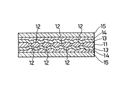
tion, as shown in Fig. 1(c), a center substrate 11 has
formed on both sides thereof recesses and/or protrusions
12... such as grooves and pits and recording films 13, 13
are formed integrally to cover these recesses and/or
13166~3
protrusions 12... . On the recording films 13, 13 there are
formed transparent adhesive layers 14, 14 and transparent
protective plates 15, 15 are securely bonded thereby.
The process of manufacturing the optical recording
medium described above comprises the steps of first forming
recesses and/or protrusions 12... , as shown in Fig. 1~a),
and then forming the recording films 13, 13 by spattering et
cetera as shown in Fig. 1(b).
As recording films 13, 13, magneto-optical recording
medium films formed as a laminate of 4 layers, namely
Al/AlN/(Gdo~6 Tb 0~4 ) 0,28 Fe 0~2/AlN, et cetera is available
Of course, this means no limitation, and besides GdTbFe type
as such, magneto-optical recording medium in film form made
of some other material or even recording medium film of
phase change type using Te ~type utilizing crystalline-
amorphous phase change) is available.
Then, a transparent adhesive is applied on the afore-
mentioned recording films 13, 13 for formation of adhesive
layers 14, 14, and the transparent protective plates 15, 15
are securely bonded thereby. As the aforementioned adhesive
is applied an ultraviolet ray curing resin or the like.
According to the aforementioned composition, the
recording films 13, 13 are formed on both sides of the
center substrate 11, hence with the recording films 13, 13
formed on the center substrate 11 warping of the center
131g6~3
substrate 11 can be prevented.
Since the recording films 13, 13 are equal or closely
similar in thermal expansion coefficient, they are deemed
equal in dimensional change due to changes in te~perature.
Hence, even if the dimensions of these recording films 13,
13 should be different from those of the above center
substrate 11, the force resulting from this difference in
dimensions acts on the center substrate 11 from both sides
thereof at equal magnitudes. If forces of equal magnitudes
act on both sides of the center substrate 11, these forces
are offset, this resulting in no warping of the
aforementioned center substrate 11.
As to the aforementioned transparent preventive plates
15, 15, there is no necessity of forming the recesses and/or
protrusions 12..., it is, therefore, not necessary to take
the ease of formation of recesses and/or protrusions into
consideration. Hence, the range of materials to choose
from, is that much increased, this enabling selection of
materials with emphasis on optical performance and
protective function required of the transparent protective
plate 15.
Although in this embodiment, the recesses and/or
protrusions 12... are formed on both sides of the center
substrate 11, formation of the aforementioned recesses
and/or protrusions 12... can be made by means of a pair of
i316603
stampers attached to the die/s, in case the center substrate
11 is a polycarbonate (hereinafter called "PC") substrate
macle by injection molding.
This way, the trouble of doing center alignment of
grooves each time can be dispensed with when 2 sheets of
optical recording substrate are bonded together~ That is,
by doing position adjustment of the aforementioned stamper
in advance, center alignment of grooves formed on both sides
of the center substrate is easily feasible and, moreover, if
this- center alignment of grooves is done once, reproduced
center substrate 11 with grooves is bound to have the
identical groove center.
Thus, if the groove's centers can be aligned on both
sides, the equilibrium error possibly occurring when the
optical recording medium is set on the player and rotated
can be easily eliminated or minimized.
By the way, it is not always necessary that the afore-
mentioned center substrate 11 must be transparent, and as
its material can be used, besides the aforementioned PC
substrate, also ABS resin, melamine resin, glass, ceramics
et cetera. As to the method of preparing the center
substrate 11, extrusion molding, casting et cetera are
applicable in addition to injection molding, and the epoxy
resin plate or acrylic resin plate molded by the casting
method are well usable as materials of the center substrate
1 0
131~603
The signal quality of the optical recording medium, for
in!;tance, the relationship between the recording bit length
and the carrier-to-noise ratio was measured using as the
aforementioned transparent protective plates 15, 15 (1)
glass plate, (2) extrusion-molded PC plate and (3)
injection-molded PC plate, and the result was as shown in
Fig. 2.
According to the measured data, the optical recording
medium using an extrusion-molded PC plate was comparable
with that using glass plate in carrier-to-noise ratio, and
the former turned out to be extremely suited as material of
transparent protective plate 15. Meanwhile, the optical
recording medium using injection-molded PC plate was lower
in carrier-to-noise ratio than that with glass plate, the
former not necessarily suitable as the transparent
protective plate 15.
There is a difference between an extrusion-molded PC
plate and an injection-molded counterpart also in a
difference in refractive index in the direction along the
plate and the direction vertical thereto (hereinafter called
"vertical birefringence"), as shown in Fig. 3. That is, an
extrusion-molded PC plate is smaller in vertical
birefringence, and superior in optical isotropy to an
injection molded counterpart. With glass plate birefrin-
131~3
gence was practically noticeable.
Further, there is also a difference between anextrusion-molded and injection-molded PC plates ln the ease
of forming the recesses and/or protrusions 12... , this
being attributable to the difference in the method of
manufacture. And in this respect an injection-molded PC
plate is superior, that is, easier for formation thereof
than an extrusion-molded counterpart.
For the reasons as described above, an ideal optical
recording medium is obtainable by using an injection-molded
PC plate as the center substrate 11 in which the recesses
and/or protrusions are formed and by using an extrusion-
molded PC plate as the transparent protective plate 15, 15
which is required to be superior in optical isotropy. This
also contributes to the desired reduction in inside stress
of the optical recording medium for an extrusion-molded PC
plate and an injection-molded counterpart are similar in
thermal expansion coefficient.
Needless to say, the aforementioned center substrate 11
need not necessarily be an injection-molded PC plate, and an
extrusion-molded counterpart may be used instead. In order
to form the recesses andtor protrusions 12... in an
extrusion-molded PC plate the PC plate is placed between a
pair of patterned dies and then pressed inward from both
sides. When the temperature is kept at approximately 100C,
1316603
the aforementioned recesses and/or protrusions 12... such as
grooves can well be transferred onto the plate.
The optical recording medium of the present invention
need not necessarily be disk-shaped, and may be formed as a
card or the like as well.
As described above, the present invention relates to an
optical recordinq medium comprising a center substrate with
recesses and/or protrusions formed on at least either of its
both sides and recording films formed on both sides of the
center substrate, transparent protective plates stuck to the
recording films respectively.
The aforementioned center substrate may possibly be of
PC resin made by injection molding.
This center substrate may also be of a synthetic resin
made by cast molding.
The aforementioned transparent protective plate may
possibly be of PC resin made by extrusion molding.
This transparent protective plate may also be of glass.
Further, the aforementioned center substrate and trans-
parent protective plate may possibly be made of materials
similar in thermal expansion coefficient.
Further still, it is also possible to have the afore-
mentioned center substrate made of PC resin by injection
molding, while using a extrusion-molded PC resin as the
aforementioned transparent protective plate.
13l66o3
The method for manufacture of the aforementioned
optical recording medium comprises the steps of first making
the center substrate having formed recesses and/or
protrusions on at least either of both sides thereof, then
forming the recording films on both sides of the center
substrate and thereafter sticking the transparent protective
plates to the recording films respectively.
In the aforementioned process for manufacture of the
optical recordi-ng substrate the recesses and/or protrusions
may possibly be formed on both sides of the center substrate
by means of a pair of stampers attached to the die in the
course of injection molding.
In the aforementioned manufacturing process the
recesses and/or protrusions may also be formed on both sides
of the center substrate by first by preparing a material
plate by extrusion molding, then placing it between a pair
of dies and pressing inward from both sides.
This way, it is possible to obtain a highly reliable
optical recording medium, which is prevented from warping of
the substrates constituting the optical recording medium,
and thus safe from exfoliation of the recording film or the
like, even when the optical recording medium is subjected to
sudden changes in temperature or the like.
Further, in selecting the trans?arent protective plate,
emphasis may be placed on the optical performance and pro-
.
,,, ,.-.~ . . .
-
13~03
tective effect required of a transparent protective plate
re~ardless of the ease of forming recesses and/or
protrusions such as grooves, hence a marked improvement in
carrier-to-noise ratio, isotropy and the like can well be
hoped for.
Further still, the relative positional precision of the
recesses and/or protrusions formed on both sides of the
center substrate can be easily improved.