Note: Descriptions are shown in the official language in which they were submitted.
2L316~1 1
BackE~ the Invention
1. Field of the Invention
The present invention addres~e~ a problematic
phenomenon in well fluids, such a~ dr~lling mud~, for which
the term "sag" has been coined. Sag occur~, for example,
when circulation of the fluid i~ stopped for a period of
time, e.g. when the drill string must be tripped from the
well, and is caused by the resulting settling or
Qtratification of the fluid whereby "heavy spots" develop.
Sag can al80 involve movement or chifting of the fractions,
particularly the "heavy spots," where components such a~
barite have become concenkrated. Sag may not occur
throughout an entire well, but nevertheless, its occurrence
in even a small section of the well can cau~e the problems
referred to below.
Such setkling is not particularly problematic if the
well is a vertical or near vertical. The magnitude of the
problem is also relatively small if the well, or the section
of the well in question, i~ nearly horizontal. However, if
the well or a section thereof has a relatively high
deviation angle (i.e. angle with respect to vertical), but
falling well ~hort of 90, ~ag problems can become
particuarly severe. The advent and recent stride~ in
extended reach drilling, which have resulted in relatively
highly deviated well~, e.g. wells with deviation angles of
20 or more, has brought sag problems currently into focus
in the industry.
Among the problems cau~ed by sag phenom~na are qticking
of drill pipe, difficulty in re-initiating and/or
maintaining proper circulation of the fluid, po~sible loss
of cireulatlon and di~proportionate removal from the well of
lighter components of the fluld.
2. Descri~tlon of the Prior Art
Prior efforts to control sag phenomena have included
modification of muds or drilling fluids by altering
parameters ~uch as the yield point, which were believed to
affect sag. However, the ba~is for such variations was
mainly actual ~ield experience which, because of the
, . . .
.
~ _3_ 1 3 1 6 8 1 r
inability to know with certainty precisely what i~ occurring
downhole, involved a certain amount of gues~ work.
Technique~ have been developed for te~ting and/or
analyzing other propertie~ of well fluids, in a laboratory
environment, but these were not intended to analyze sag, and
none of them i~ completely qatisfactory for that purpo3e.
More ~pecifically, one of theqe techniques was u3ed to
test for a phenomenon known as "top oil ~eparation" in
invert emul~ion drilling fluidg. Top oil ~eparation doeq
not, to the inventors' knowledge, occur in actual downhole
conditions, only in laboratories and the like, but i~
sometimeq considered a factor which should be controlled out
of an excess of caution. Top oil separation does not
involve the true statification of the drilling ~luid which
occurs in connection with sag, but merely referq to the
~weating or bleeding of a relatively thin layer of pure oil
to the upper qurface of a volume of mud, with the remainder
of mud remaining more or le~s homogenous. In accord with
this technique, sampleq of the mud were placed in teYt tube~
which were heated in an oven9 whereafter the amount o~ oil
which had Qeparated to the top was meaqured. Coincidently,
in at lea~t qome quch procedureq, the tubes were placed in
the oven at an angle, simply becau~e the length of the tubes
and the 3 ize of the oven did not permit upright
orientation. The reqult was not necesYarily a measure of
~ sag, or true stratirication, which may or may not have;~ occurred in the test. Furthermore, the numerical result was
merely a quant$ty or percentage of oil and waq not related
to time.
Other systems, kno~n a~ "flow loops~ have been devised
~or studying the cir¢ulation of cutting3. While it is
conceivable that ~uch ~ystems might be utillzed to test or
predict qag, because they are really intended to analyze
cutting cir¢ulation, and then due to the ~ize of typical
~ 35 well cutting~, it has been felt, perhaps correctly, that the
- te t systemq should be approximately nfull scale. n Thu9 ~
- they are large, expensi7e, and may require a relatively high
~ degree o~ skill and~or training to operate. Furthermore,
~ i
1 3 1 6 8 1 r
the flow loop3 are, by nature, intended to ~imulate and
analyze a dynamic condition, i.e. circulation, and not the
qtatic condition, when circulation i~ lo~t or ~topped, which
re~ults in 5 ag.
Other method~ have been u~ed to te~t the ~hear ~trength
of drilling fluid~ u~ing conventional rheometer~. However,
thi~ neither ~imulate~ nor accurately predicts sag.
- 35
.
- ~ `
1 31 68, ~,
Summa~ the Invention
The pre~ent invention provide~ an apparatu3 and a
method for ~imulating and analyzing sag phenonmena in well
fluids wherein the results may be and preferably are
expressed as a function of time, and which can be perfor~ed
with a relatively simple apparatus, on a 3mall ~cale, in a
laboratory or even in the field. Preliminary results
indicate that the method and apparatus of the present
invention are not only far guperior to any prior known
technique, but in fact, and rather surprisingly9 test~
performed using the present invention have ~hown that the
kinds of properties and or parameters which have been relied
upon in the past as indicators or control features of sag
phenomena are unreliable, and in some cases, irrelevant,
i.e. these propertie9 and/or parameter~ are not in fact
related to Qag in such a way that they can be reliably used
to predict or control sag.
In particular, in the method of the present invention
an elongate container containing a sample of a fluid to be
tested is mounted at an angle with respect to vertical to
~imulate a given well deviation angle. A parameter of the
~ample which i~ indicative of the sag of the sample i8
measured.
Preferably, $hi3 parameter is measured repeatedly and
more specifically continuou31y, over a subqtantial period of
time, and functionally related to time.
If the container is mounted at a non-perpendicular
angle to vertical, then its center of mass can ~erve as the
a~orementioned parameter. This parameter can be measured
either directly or indirectly. In preferred methods, the
oontainer i~ ~o ~ounted on a ~orce responsive device which
provides a mea~ureable, variable indication of the center o~
mas~ o~ the container, and lt is that indication which i8 ~0
measured.
The apparatus according to the present invention
include~ such a force respon~ive device, mounting mean~
associated with the force responsive device for ~electively
mounting a body at various angleR, and an elongate contalner
1 3 1 6 8 ' r
mean~ capable of mounting on the mounting means at an angle
with respect to vertical.
Even more preferably, the force responsive device
comprise~ a pivoted arm, the indication of center Or mass
belng provided by virtue Or movement of one end of the arm
in a fir~t direction, e.g. vertical.
Measuring means for measuring this lndication may
compri~e a strain gauge connected to the aforementioned end
of the arm and adapted to produce a signal which i~ a
function of the force exerted on the ~train gauge in the
firat direction by the arm. Thi~ signal may be received by
approprlate mean~, functionally related to time, and the
Punction recorded, e.g. by a chart plotter.
The preferred method and apparatu~ al30 involve
sub~ecting the sample to heat to simulate a downhole
condition, mean~ for ~ealing the sample ~rom the surrounding
environment while still permitting volumetric expansion and
contraction of the sample, and several salient 3ubsystems of
the apparatus.
A principal ob~ect of the present invention is to
provide an apparatus and method for ~imulating and analyzing
sag phenomena in a slant tube containing a fluid ~ample.
Another ob~ect o~ the present invention is to provide
Quch an apparatus and method in which the reqult~ are
obtained in the form of a function of time.
Still another ob~ect of the pre~ent invention is to
provide ~uch an apparatu~ and method in which the center of
ma~ of the slant tube containing the ~ample is u~ed as the
principal variable to be functionally related to time.
Still other ob~ect3, features, and advantage~ of the
pre~ent invention will be made apparent by the following
detailed de~cription, the drawlng~, and the claims.
- : ' ';
.
:
7 ~ 1 3 1 6 8 I r
Brief De cr~ion of the Drawing
Fig. 1 i~ a partially schematic ~ide Yiew of an
apparatu~ according to the present invention, with the oven
hou~ing ~hown in croqs-section9 and the remainlng parts
~hown ln elevation.
Fig. 2 is a top plan view taken on the line 2-2 o~ Fig.
1 .
Fig. 3 19 an enlarged side elevatlonal vle~ of one of
the pivot arm3 o~ the apparatus with associated parts,
lncludlng mounting ~ean~.
Fig. 4 i_ a detailed sectional vlew taken on the line
4-4 of Flg. 3.
Flg. 5 i. a detailed view of the pivot mechani~m taken
on the llne 5-5 of Fig. 6.
Fig, 6 i9 a ~lde view of the pivot mechanlsm taken on
the line 6-6 of Flg. 5.
Fig. 7 iq a Purther detailed vlew of the pi~ot
mechanlsm taken on the llne 7-7 of Fig. 5.
Flg. 8 19 an enlarged ¢ros~-sectional view o~ the
container mean~. -
Fig. g is a detailed crosq-~ectional vlew through one
of the cloqure member~ taken on the llne 9-9 of Fig. 8.
; Fig. 10 i3 a view ~imllar to that of Fig. 9 ~howing the
valve ln open position.
, ~
;
` ~ 30
,
~,
~- ~35 ~
.
. ~ ' '.
" '
3 1 6 ~ , ,
Detailed Description
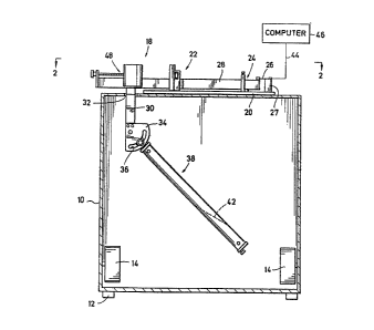
Fig. 1 and Fig. 2 illu~trate an exemplary embodiment of
an apparatu~ according to the present invention. This
apparatus comprises an oven having a hou~ing 109 foot pads
12 for vibration isolation and interior heaters 14. The
housing 10 also includes a door 16 permitting access to the
interior of the oven.
On and in the oven 10 are arranged a battery of
apparatuses 18 ~or handling the fluid samples to be
teqted. One Or the apparatuses 18 will be described in
detail, the others being identical. More partlcuarly9 each
apparatus 18 includes a mounting plate 20 supported on the
exterior Or the upper wall of the oven 10. On plate 20
there is mounted a pivot mechanism 22, to be de~cribed more
rully below, a limit device 24, and a strain gauge 26.
Mechani~m 22 mount~ a pivot arm 28 for pivotal movement
about a transverse horizontal axis, so that the ends of the
arm 28 move in the vertical direction, which in this
exemplary embodiment i~ nthe first directlon."
Ad~acent the end Or arm 28 distal 9 train gauge 26,
there is attached a mounting mechaniqm to be described more
fully below. Briefly, the mounting mechanism includeq a
link member 30 which dependq downwardly from arm 28 and
pas~es through an opening 32 in the upper wall oP oven 10
To the lower end of link member 30 there i9 attaohed a plate
34 having an ad~ustment 310t 36 which allows a container
means 38 to be mounted on plate 34 selectively at various
angles with respect to ~ertical. If necessary, a weight may
be suspended rrom the ~ree end Or the container meanq, i.e.
di~tal that end which i8 hung rrom plate 34, ror calibration
prior to te9tlng.
It can be ~en that, lr the center Or mas~ o~ the
container meang 38 should ¢hange, by virtue Or ~ag o~ the
~luid ~ample, e.g. ir ~h~ contents stratlry so that heavier
~eomponents lie below the line 42, th~ moment exerted by
virtue Or the welght Or container means 38 will ohange, and
arm 28 will tend to pi~ot. Even though actual ~ovement o~
~arm 28 may be too small to readlly ob~er~e with the naked
~ .
-9- 1 31 6~3 ~
eye, there will in fact be sufficient movement to change the
~orce exerted on ~train gauge 26 by the attached end of arm
28. Strain gauge 26 continuously mea~urea that force over a
period of time. The length of tlme choQen ~er the te~t
qhould be long enough ~o provide a realistic prediction of
the 3ag behavior of the ~ample in question in actual u~e.
Pre~erably, the te~t ~qhould be continued untll the ~luld
sample ha~ qtabillzed, i.e. until no qigni~icant chan~es
have occurred ~or ~ome time.
10Straln gauge 26 co~municate3 by a wlre 44 with a
recelver 46, shown diagrammatlcally in Fig. 1. The receiver
46 may be, ror example, a computer whlch recelve3 the signal
produced by ~train gauge 26, which iq an indication Or the
force being exerted by arm 28 on the strain gauge, and thu~
in turn an indication of the center of mas~ of container
mean~ 38, and functionally relates tho~e mea~urements or
- readings to time. The resulting ~unction i~ recorded in one
or more appropriate media. For example, it may be recorded
in the memory of the computer, and/or by a chart plotting
mechani~m operatively a~ociated with the receiver 46. Some
suitable means, which may be incorporated into the ~o~tware
~or computer 46, ~hould be u~ed to screen out tho e data
obtained before the de~ired test temperature l~ reaohed,
i.e. during the initial heating of the sample.
25In order to effect an initial po~ltlon of arm 28, and
thereby an ln~tial read~ng of ~traln gauge 26, a balancing
mechanism 48 i~ as~oc~ated with the end of arm 28 dlstal
~train ~gauge 26. Thig balanclng mechanism, to be de~¢ribed
more rully below, i8 ordinarily initially ad~u~ted ~o that a
relatively ~mall force l~ exerted on straln gauge 26. The
limlt means 24 llmit tbe ver~i¢al movement Or arm 2B ~o a~
to~p~otect the ~train gauge 26 rrom exce~si~e ror~e.
Turning now to Flg. 3, the arm 28 and parts a~soclated
therewlth will be descrlbed ln grsater detail. The~ a~r~ 28
~- 35i3 ~orm~d in two ~ection~, 28a and 28b dl3po~ed in end-to-
~end relation. The ad~acen~ end~ are ~andwlched betwe~n a
pair o~ plats~ 50 and connec~ed to ths plat2s by screw~ 52
~so~th~t ection~q 28a and 28b are rlgldly conneoted together
.
. -
.
- 1 0- 1 3 1 ~
- (See Fig. 7). Section 28a is formed of a thermal insulator material, such aq a quitable rigid plastic, whil~ ~ection
28b may be formed of a metal, ~uch as bras~.
The ~upport plate 20 i~ secured to the upper wall of
over 10 by crews, one of which iq ~hown at 54. Thermal
insulation (not ~hown) i9 preferably 1nterpoqed between the
plate 20 and the top of the oven 10. Ad~acent the ~train
gauge 26, plate 20 ha~ a ~tepped ~lot therethrough,
elongated in the direction corre~ponding to the length of
arm 28. Thi~ qlot includes a narrow uppermo~t portion 56a
and a wider lower portion 56b. A mounting block 27 for the
~train gauge 26 can thuQ be ad~u~tably secured to the plate
20 by a ~crew 58, the ~hank of which paqse~ through portion
56a of the 31Ot, and the head of which i9 received in
portion 56b and abuts the ~tep formed between portion~ 56a
and 56b. If it i~ de~ired to move the strain gauge clo~er
to or farther away from the ad~acent end of arm portion 28a,
screw 58 can be loo~ened, and the ~crew can slide along the
slot 56a, 56b a3 the ~train gauge i~ moved to the desire
po~ition, whereafter screw 58 i~ re-tightened.
The ~train gauge 26 ha~ one end sandwiched between
apertured member~ 60, which provide a clean edge at which
gauge 26 can ~lex. Member~ 60 and the engaged end Or gauge
26 are ~ecured to the end of arm ~ection 28a by a ~crew
62. The other end Or gauge 26 is 31milarly ~andwiched
between in3ulator~, one of which i5 3hown at 64, and secured
to mounting block 27 by screw 66. Strain gauge 26 i9
adapted for produclng the aPorementioned varlable output
~ignal which is conveyed along wire 44.
; 30 The balancing mean~ 48 lncludes a weigh~ 68 which rest~
on the upper ~urrace of arm sectlon 28b and lnclude~
- dependlng legs, one o~ which i3 ~hown at 68a, ~hich straddle
arm qection 28b. Thu~ 9 welght 68 can ~llde along arm
eet1On 28b, and i~ guided in ~uch movement by leg~ 68a.
-~ 35 In order to more ea~lly and accurately efrect such
oYements, an ad~u~tlng serew 70 of sultable length l~
threaded lnto weight 68 parallel to the length Or arm 28.
The end o~ the ~orew ho a redu¢ed diameter neok which 1s
-
-: :
: ~
~; :
1 3 1 6~ 1
rotatably supported, but restrained against ~ongitudinal
movement, by an upstanding plate 74 affixed to the outer end
Or arm section 28b by ~crews 76. A knob 72 integrally fixed
to screw 70 is disposed on the outer side of plate 74 for
engagement by the operator.
The link 30 of the mounting means is connected to arm
section 28b by screws 78, coun~ersunk in arm section 28b so
as not to interfere with weight 68. Screws 78 also pass
through a ~him 807 which can, as a practical matter, be
con~idered part of the mounting means, and indeed part of
the link 30. Shim 80 algo ~erves as a baffle to minimize
heat lo~ through aperture 32.
Referring now ~ointly to Fig3. 3 and 4, the mounting
means further comprises an adjustable link 82 having a flat,
plate-like arm 82a lying in a reduced thickness area 30a of
link 30 and extending angularly from link 30 beyond plate
34. Link 82 further comprise~ a cylindrical portion 82b at
the outer end of arm 82a. Link 30, arm 82a and plate 34
have aligned bores 86, 88 and 90, respectively, the bore 88
being larger in diameter than the bores 86 and 90. In these
aligned bores there is di~posed a pivot pin 84 whose
diameter i~ stepped to correspond to the diameters of the
bores. Because the central step is greater, pin 84 is
sandwiched between link 30 ahd plate 34 and thus retained in
the bores as long as link 30 and plate 34 are connected
together. This connection is acheived by screws 92. Arm
82a is, in turn, secured to plate 34 by the nut and bolt
a~embly 94, the bolt of which extends through slot 36 in
plate 34. By loosening the nut and bolt as~embly 94, link
82 can be pivoted about pin 84 to a desired te~ting angle,
the movement being premitted by ~liding of the bolt of
assembly 94 in arcuate slot 36, the center of which i9
coincident with the axi~ of pin 84. When the de~ired angle
has been achieved, ~he nut and bolt assembly 94 i~ tightened
to maintain that angle.
The container mean~ 38, to be described more fully
below, includes an outer cylindrical casing 96 in the end of
which i3 di~po~ed a closure plug 98. The closure plug 98 i~
.
.
-12- 1 31 6~ ~
sec~red in casing 96 by a transverse pin 100 and sealed with
respect to casing 96 by O-ring 102. Closure plug 98, while
part of the container means, can also be considered part of
the connecting means in that it cooperates with cylindrical
portion 82b of the movable link to suspend the container
means 38 with a frictional bindine type action. More
specifically, there is a cylindrical recess 98a extending
axially into the center Or the outer end of plug 98. Link
portion 82b is sized for a sliding fit in recess 98a. When
emplaced therein, ag shown, the moment imposed by virtue of
the weight of the container means 38, coupled with the
manner in which it is suspended angularly from one end, will
cause the aforementioned frictional binding effect, whereby
container means 38 is suspended from the mounting means, but
easily removable without disturbing the content.s. It is
noted that section 82b of the movable link has a notch 82c
for receiving pin 100.
The limit means 24 includes means for limiting both
upward and downward movement of` the outer end of arm section
28a. Limit means 24 includes a saddle-like body 104 which
straddles arm section 28a and is secured in any suitable
manner to plate 20. It should be noted that the height of
the recess in body 104 is greater than that of arm section
28a, so as to permit the desired vertical moment. However,
upward movement of arm section 28a is limited by an
adjustable screw 106 which extends downwardly into the
recess of the body 104 for abutment with the upper surface
of arm section 28a. The limit means further comprises
another adjugtable screw 108 threaded directly into arm
section 28a and extending downwardly therefrom for abutment
with plate 20 to limit downward movement of arm section
28a.
Referring now jointly to Figs. 3 and 5-7, the pivot
as~embly 22 will be described in greater detail. The pivot
assembly is designed to minimize friction therein, upon
pivotal movement of arm 28, so as to maximize the
sensitivity and accuracy of the measurements of variations
in the position of arm 28 as it effects the force applied to
-''.
. :
~ ' '.
-13- 1 3 1 6 ~ ,
strain gauge 26. To this end, th~ pivot a~sembly comprise3
- two main ~ubas~emblie~: a ba~e ~ubaq~embly, which in the
illu~trated embodiment is connected to the support 20, and a
contact suba~sembly, connected to the arm 28, having 3harp
contact surface means engaglng the ba~e and defining the
pivot axis ror the arm 28. However, it should be
appreciated that arrangement~ could be devi~ed in which the
contact subag~embly iq carried by the ~upport, and the base
subaqsembly carried by the pivot arm. It ~hould al~o be
understood that the manner oP connection o~ the variou~
part3, a~ well aq thelr form, could be varied. In
particular, that subassembly which is connected to the
~upport can be ~o connected either directly or indirectly,
the referenceR herein to connection to the ~upport being a
convenient way of indicating that there i~ Qome connection
between that subas~embly and the qtationary parts o~ the
apparatus.
Turning now to the illustrated embodiment, the base
subas~embly compriseq an upstanding plate-like main ba~e
member 110 having a saddle or inverted U-shaped
con~iguration, with legs 110a qtraddling the arm 28 and
re3ting on support 20. The legs 110a are connected to
support 20 as by screw~, one of which i9 shown at 112 in
Fig. 6. The base quba~sembly also comprises a recessed base
member 114 Qecured to one Or the broad sides of member 110,
re~erred to hereina~ter as the nforwardn or "~ront" 3ide by
screw~ 116. Me~ber 114 has a generally ~addle or inverted
U-shaped configuration when viewed from the Pront. Thus, it
has leg portion~ 114a lnkerconnected by a bridge portion
114b. Leg portions 114a further extend rearwardly Prom the
brldge portion 114b ~o abut member 112. There are also a
pair Or laterally ~paeed apart rearward pro~ectlons 114c
extending rearwardly fro~ the upper~03t part o~ bridg~ 114b,
and also abutting ~ember 112. Thu~, ~between the upper and
lower rearward pro~ect~ons on each ~ide, respactlvely, of
member 114, there are derined a pair Or reces~es 118 ope~ing
rearwardly and laterall~ outwardly.
; The contact ~ubasse~bly of the pl~ot meohanism includes
-14- 1 3 1 6~ 1 ~
a T-shaped carrier 120 the leg of which is secured to the
end of arm section 28b by screws 12~, and the arms of which
are received in respective recesses 118. Each of the arms
of the T~shaped carrier 120 carries a respective adju~table
contact pin 122 or 124. The contact pins are arranged
vertically and have sharpened lower points. They also have
threaded sections, mating with threaded bores in the arms of
carrier 120, so that the positions of the pins can be
adjusted.
The sharp points of the two pins 122 and 124 define,
with a minimum of surface engagement, and therefore a
minimum of friction, the pivot axis for the arm 28. It can
be seen that the axis thus defined lies horizontally and
transverse to the arm to effect pivotal movement in the
"first" direction defined above, i.e. a vertical
direction. The upper surfaces of the rearward extensions of
the leg portions 114a of member 114 define, within recesses
118, broad surfaces capable of engaging the sharp ends of
the pins 122 and 124 with minimum frictional resistance to
movement.
In order to resist lateral shifting of the arm 28 with
respect to the support 20 and to return the pins to their
proper position, e.g. if there is some displacement during
setting up of a test, the upper surface of the rearward
extension which engages pin 122 is provided with a shallow
recess 126 which will position pin 122 in the lateral
direction without engaging more than the necessary arnount of
surface area, i.e. without engaging more than the point of
pin 122. Pins 122 and 124 also extend upwardly through
oversized bores 128 in the aligned upper rearward extensions
114c of member 114, terminating in knobs 130 so as to
facilitate lengthwise adjustment of pins 122 and 124 within
carrier 120. The surface of member 114 which is engaged by
the other pin 124 doe~ not have to be recessed, because
longitudinal movement of arm 28 is prevented by the strain
gauge 26, and lateral movement of arm 28 is limited by base
member 110 and body 104. The amount of lateral play
permitted is less than the width of recess 126 so that, if
,.
-: .
.
'' ' ,
_15_ 1 3 1 68 r
there i3 some displacement, e.g. during test set up, the pin
122 will ride down the ineline of recess 126 and return to
its proper position.
Referring now to Figs. 8-lo, the container means 38
will be de~cribed in greater detail. It has already been
mentioned that the container means includes an outer casing
96, the upper or attachment end of which is closed by a
closure plug 98 retained by pin 100 which passes laterally
through aligned bores in the casing 96 and the closure 98.
The portions of pin 100 which are aligned with and pass
through the wall of casing 96 in use are necked down or
reduced in diameter as indicated at 100a. Rings (not shown)
are placed In areas 100a to hold pin 100 in place until the
container is pressurized. Thereafter, pins 100 are
frictionally retained by virtue of the pressure urging
closure 98 outwardly. Closure 98 also has a knurled outer
flange 98b which overlies the edge of casing 96 for ease of
emplacement and removal of closure 98.
The lower or free end of casing 96 is likewise provided
with a removable sealed closure member or plug 132. Like
closure 98, closure 132 is sealed with respect to casing 96
by an O-ring 134 and is provided with a knurled outer flange
138. Also, closure 132 is held in place by a pin 136
similar to pin 100, except that it includes reduced diameter
end projections 136a for suspending a weight, when such is
used for initial calibration.
Unlike closure 98, closure 132 does not have a large
central recess corresponding to recess 98a because this
closure is not used for the end of the container which is
suspended from the mounting means. On the other hand,
closure 132 is provided with a pressurization port system,
including a valve for opening and closing that system,
whereby the interior of casing 96 can be pressurized. This
port system includes a lengthwise bore 138 extending
completely through closure 132, and a lateral bore 140
extending from the outer diameter o~ closure 132 laterally
inwardly to intersect bore 138 at a right angle. The outer
portion of bore 138 is enlarged, and the enlarged portion
~~ -16- 1 31 6~ 1 i
includes an innermo~t ~mooth part 13~a forming a ~eal
surface, and a threaded outermo~t part 138b.
A valve member 142 has an outermo~t knurled knob 142a
and a ~hank which extends into the enlarged portion 138a,
138b of the lengthwise port 138. Adjacent knob 142, this
shank i~ threaded, as indicated at 142b, to mate with port
section 138b. The innermost end portion 142c of the shank
of the valve member carrieg an 0-ring 144 for sealing
againqt port section 138a a~ well as an end seal 146 which
can seal againgt the ghoulder formed between section 138a
and the smaller diameter ~ection of port 138 inwardly
thereof.
Fig. 9 shows the valve member 142 threadedly advanced
toward to engage seal 146, and it can be seen that, since
port 140 communicates with port 138 outwardly of seal 146,
and since the outer portion of port 138 is also sealed by 0-
ring 144, pressure cannot escape from the interior of casing
96 when the valve 142 i~ in the position of Fig. 9.
When it is desired to pressurize or depressurize the
interior of the caging 96, valve member 142 can be backed
away by threading outwardly to space seal 146 from the
opposed shoulder of port 138 as shown in Fig. 10. For
pressurizing the casing 96, the outer part of bore 140 is
enlarged and threaded at 140a, and the casing i3 apertured
at 96a, to receive a standard fitting 148.
In addition to ca~ing ~6, container mean~ 38 also
comprises a glas~ tube 150 digposed within casing 96. Tube
150 can be slidably emplaced in or removed from casing g6,
but there is sufPicient clearance therebetween ~o that~ when
the casing 96 i~ pressurized in the manner ~ust de~cribed,
pressure can communicate with the open upper end of tube 150
so as to pre3surize the contents of the tube.
It is, however, desirable to isolate those contents,
which comprise the sample being te~ted, whlle ~till
permitting volumetric expansion and contraction thereof, as
will be induced by the pres~urization and/or heating of the
~ample. Thus~ a closure pi~ton 15Z of a free floating type
19 di~po~ed in the open end of tube 150. Thi3 piston is
.. , , .................................... . ~.:
- , .
.: . .
-17~ 1 31 6 ~
sealed with respect to tube 150 by an 0-ring 154.
~ or optimizing the isolation of the sample, the pi~ston
152 is provided with a lengthwi.se bore 156, the outer end o~
which is enlarged and threaded to receive a plug 158. The
drilling fluid sample can be placed in tube 150 followed by
the piston 152, without plug 158. Piston 152 is forced
inwardly until the operator can see the drilling ~luid
entering bore 156, thereby indicating that as ~uch air as
possible has been bled off therethrough. Then, plug 158 is
emplaced.
Thereafter, the glass tube 150 is installed in casing
96, whose ends are closed by the closures 98 and 132. The
interior of casing 96, and thus the contents of the tube
150, are then pressurized by opening the valve 142 and
introducing a suitable fluid (gas or liquid) under pressure
through port 140. The te.st pressure may be just high enough
to prevent boiling of the sample at the desired test
temperature, or it may be higher so as to simulate a
downhole condition. When the pressure has reached the
desired point, which can be determined by gauge means well
known in the art, valve 142 is closed, fitting 148 is
removed, and the container means 38 is ready for
installation in the oven.
Movable link 82 is adjusted to the desired angle, and
then its cylindrical portion 82b is installed in the recess
98a, with slot 82c receiving pin 100 and thus indexing the
container means 38.
Depending on the nature of the test or analysis to be
done, similar containers can be mounted on the other
apparatuses 18. For example, each container might contain
an identical fluid sample, but the angles at which the
various containers are oriented might be varied from one
apparatus 118 to the next. In another type of analysis, the
angles might be identical, but the composition of the
samples in the respective containers might be varied.
Next, each of the arms 28 is balanced utilizing the
balancing means 48. Then, the oven 10 is closed and the
heaters 14 activated to heat the contents of the containers
~:~
- ,:
.
~ 18- 1 3 1 6~ 1 ~
38 to a desired temperature. When the desired temperature
i9 reached, if not before, the computer 146 can be engaged
to begin recording the meaqurement~ continuou~ly taken by
the strain gauge 26, functionally relating these
measuremen~ to time, and recording the functional
relationship. That function is known as the "sag ~ignature"
~or the sample in queqtion. The computer 46 may chart or
otherwise record the sag signature. It may al~o integrate
the sag signature, the integral being known as the "sag
coe~icient.~ One or more computers or other receivers 46
can be u~ed to produce separate runctions and records
thereof for each o~ the apparatug 18 and to ~urther analyze
the data in any desired manner.
It can be seen that, as stratification of the contents
of a container 38 occurs, the heavier components will settle
toward the outer, lower end o~ ~he container 38. This
alters the center of mass of that container and its
contents, which in turn alters the moment placed on the
.r mounting mean~ by the container. This will effect minor
vertical pivotal movements of the arm 28, altering the force
thereor on strain gauge 26, and the signal produced by the
qtrain gauge and analyzed by the receiver 46 will vary.
Using the method and apparatus of the invention,
surprising results have already been obtained. In
particular, it ha~ been found that vi~cosity ~actorq- ~uch as
yield point, ten minute and ten ~econd gel strengths, and
plastic vi~cosity, which have previously been used either to
predict and/or attempt to control ~ag are unreliable, and in
some cases irrelevant, to the sag phenomenon. Using this
apparatus and method, variations in the composition of a
fluid can be tested, conveniently, on a small scale, either
in a laboratory or in the field, until a mud composition
which will avoid sag problems under the antioipated field
; conditions is tailored. Also, information generally u~eful
in formulating drilling fluids can be gained by the use of
;~ thi~ method and apparatu~.
Various modi~ications of the exemplary embodiments
described and illustrated herein will suggest themselves to
:
'
, .
1 3 1 6 & I r
_1 9
tho~e of ~kill in the art. Accordingly, it is intended that
the ~cope of the pre~ent invention be limited only by the
claim~ which follow.
i
~ 35 ~
~ ' :
, - - - , 1
:
~ . . . . .
, -
. .
. .
, . . .
.