Note: Descriptions are shown in the official language in which they were submitted.
.~ `^i
" 131`-69
SIMULCAST BROADC~TING SYSTEM AND METHOD
Technical Field
This invention relates generally to simulcast radio communications systems.
Backgrolmd Art
Simulcast radio communications systems alle typically employed ~o provide
wide area one-way or hvo-way radio communic~tions services. In such a system, a source
site ~pically originates (or forwards ~om another originating site) a signal to be generally
broadcast. This signal is routed from the source site to a pluralit~ of remote sites. Each
remote site then simultaneously broadcasts the signal with other remote sites to facilitate
reception of the signal by receivers within the area covered by the system.
;~ In this way, a receiver outside the operating range of one remote site may still
be within the range of one or more other remote sites, thereby reasonably ensuring that the
receiver can recei~e the signal.
One particularly difficult problem with such simulcast systems involves
coordinating the various
I
.
.
',
`~'
. .
2 1 316 9 8 5 CM 00467H
remotQ ~ites to ensure that the sign21s are in fact
substantially simultaneou~ly broadcast by each. A
failur~ to acco~pllsh thi~ will result in instanc~s of
unacceptable reception coherence as potentially caused by
phase of~s~ts, daviation, distortion and th~ like.
Anoth~r problem arises when more than two signals
must be transmitted simultaneously: for example, a voice
signal and a data signal. Prior ~rt methods of
procesRing such combined ~ignals in a simulcast
~ environment have not alway~ heen aclequately conduciv~ to
supporting necessary levels of reception coherence.
Finally, even when initially properly adjusted
~or proper reception coherence, the operating performance
of a given si~ulcast system may vary in response to a
- 15 number of changing operating and environmental factors.
No prior art 8ystems provide ~or a ~eans of allowlng a
simulca~t system to respond in any convenient or
e~icacious manner to such circumstances.
A need exists ~or a ~imulca6t system that
provides for the ~ub~tantially simultaneous broadcast of
a ~ignal fro~ a plurality of re~ote site~, particularly
where th~ signal to b~ broadca~t itself includes at least
:; two signals. A need further Qxlsts for a system that can
adapt on~ or more o~ it operating param~ter~ to
continually provid~ tran~missions o~ acceptable reception
coher~nc0 ev~n when other operating ~actors or
nviron~ental conditions ch~nge.
S ~ arX o~ th~ I _cntion
: 3~
Thes~ n~eds and others are substan~ially met
through provision of ~he improved simulcast broadcasting
system disclosed h~rein. The system includes generally a
source ~it~ ~or providing an original ~ignal ~o be
broadcast, and a plurality of remote sites for
substan~ially simultaneou~ly broadcasting the original
signal from the source ~lte.
1~1698~ 00467~I
In one e~bodimen~, the source site provides both
a ~irst and ~ second signal (such as volce and data).
The source ~ite provides these two signals to the remote
sites discrete from one another. Only a~ter recep~ion
and appropriate processing at the remote Rite will the
~wo signals be combin~d to ~acilit~te their broadcast.
In one embodiment, the appropriate proce~sing
provided to the first and ~econd signals at the remote
sites includes introduction of an appropriate time delay
to ensure that all of the remote ~ites broadcast
substantially the sam~ signal with ub~tant$ally the same
phase relakion~hip.
In another embodiment, a ~onitoring device can be
provided to monitor broadcAst signal~ from the remote
sites, and det~rmine wheth~r th2 broadcast ~ignals
~xhibit an acceptable reception coherence. One or more
broadcas~ system parameters can then be automatlcally
varied in re~pon~ to this determination as appropriate
to improve r~ception coherence.
~rief~ D ~criPtion of th~ Drawinqa
Fig. 1 co~pris~ a ~lock diagram d~piction of
source s~te ~tructur~:
:~ ~ FigO 2 co~pri~s a block diagram depiction of
remote sit~ ~tructure;
Fig. 3 co~prise a block diagram depiction of the
re~ote de}ay module of tha remote site; and
~ Fig. 4 comprises a:block diagram depiction of a
: monitoring site.
:` 30
est Mode ~or Carryinq out the Invention
~he inventlon includes generally a sourc~ site
unit (SSU~ (100) (Fig. 1) and a remote site unit (RSU)
(200) (Fig. 21.
~'
~'
:;
,~
' :
~' ~' , .
_ 4 _ L31698~ 00467H
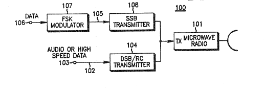
. Referrlng to Flg. 1, the SSU (100~ include
gQnerally ~ ~icrowave radio (lol) that receive~ both
audio and data input. The microwave radio ~101)
functions to transmit the two lnco~ing ~ignals in a known
~ultiplexed ~anner to the RSUs (200) as descrihed below
in mor~ d~tail.
The SSU audio p~th ~102) include~ an audio source
input (103) ~which ~ay b2 on ~it or o~f, as may be
appropriate to the application or functlon) that passe~
through a tran mi~sion bloc~ (104) con~igured ln known
manner as a double sidehand/reducecl carrier, the output
o~ which tran~mitter (104) couples to a transmitter input
port of the microwav2 radio (lol). In certain
application~, as in trunked co~unications, ~hi~ input
(103) could alternatively rec~ive high speed data, æuch
as control channel signalling.
The data path (105) includes a data source (106)
(which provides, ~or examp}e, low speed data intended to
:~ be ultimately coupled subaudibly with the audio
in~ormation). The data ~ource (106) passes through an
FS~ ~odulator (107) to a single sideband configured
I trans~itter (~08). Th~ la~er transmit~er (}08) sums to
: a transmit port of thQ microwave radio 1101).
For purpo~e~ Or ~xplanation, the audio signal can
be a fir~t 3ignal, and the data sign~l can be a second
~ignal, with th~ ultimat~ intent being to provide a
~ignal to a subscriber unit, such a8 a mohile, portable
or fixed rece~ver, in ~ combined ~ormat. Upon reception,
: th~ radio will r~nder the voice information audible, and
30 will subaudlbly proce~s and act accordingly upon ~he data
information or instruction~. It should ba noted t~at in
thiB yste~, contrary to prior art technique, the first
and second ~lgnal~ are not combined at the S5U (loo).
Instead, ~h~y are transmitted separately and discrete
: 35 from one another, in a ~ultiplexed ~anner, to the RSUs
(200).
: ~:
.
_ 5 _ 1316 9 8 ~ CM;00467H
R@ferring now to Fig. 2, an example RS~ (200)
will be de~cribed. The RSU t200) includes a repeater
structure comprised o~ two mierowave radio~ (201 and
202). Signal~ r~c~ived by th~ ~irst microwave radio
5 (201) are ~ubsequ~ntly repeated and transmitted by the
second microwave radio (202), ~ox instancP to another
~SU. Slmllarly, ~lgnal~ received ~rom down 8 ream RSUs
can be received by the ~econd microwave radio (202) and
transmitted to the SSU via the first microwaYe radio
(201). ~g~in, the~ radio~ ~201 and 202) function in a
: known manner to r~c~iv~ and tran~lt ~ultipl~xed signals,
including th~ rirst and sscond signals pro~ided by the
SSU (100~.
ThQ RSU (200) al~o includes a combinor (203) as
well under~tood in th~ ~rt. ~h~ combiner provides a high
~requency received in~ormation line t204) and a hlgh
~requ~ncy trans~it ln~ormation line ~205). A single
~ideband con~igured receiver (206) couples to the receive
line (204) and ~unctlons to receive the data information
a~ tran~mitted by thè SSU (100). A double
~ideband~reduced carri~r configurated receiver (207) also
couple~ to th~ receive line (204) and ~unctions to
: receive th~ audio information ~5 ~eparately transmitted
by ~he SSU ~100).
The output o~ both r~ceivexs (206 and 207~ is
provided to a re~ota delay modul~ (RDMI (208~, the
con~igur~tion and operation o~ which will be described in
mor~ d*tail below. ~he output (209) o~ the remote delay
. : module ~n~}ude~ recovared audio in~ormation and recovered
data i~formation, appropriately processed, delayed, and
co~bined. Thi~ combined signal can then be pro~ided to
apprspriate transmit~er equipment to allow a gen~ral
broadca~t o~ the in~ormation in a known manner.
The RSU t200~ also includes a single ~ideband
configured ~ransceiv~r ~210) that couples to bo~h high
~: frequency lines of the co~biner (203) and communicates
with ~ proc~ssor unit (211) that provi~es appropriate
.
`~ ~
~ 3 ~
- 6 - CM-00467H
control instructions to the RDM (?08) a~ also described
in more detail below.
Referring now to ~ig. 3, the RDM (208) includes a
data path (301) and an audlo path (302). The data pa h
(301) couples to ~he ou~put of the ~ingle ldeband
receiver t206) through a 600 ohm input unit (303),
following which th~ ignal is appropriately clipp~d and
squared ~3G4) in a known ~anner. Th~ data signal is then
passed through an appropriat~ delay unit (305). The
delay un~t (305) introduces a time delay in any
approprlate known ~anner to accomplish a predeter~ined
~elay of propagation o~ the da~a ~iynal to th~
transmitter o~ the RSU t200). (The purpose o~ th~s delay
is to Qn~ur~ that all RSU~ (200) transmit a given source
signal as providQd by th~ SSU ~100) at 3ubstantlally the
sama tl~e. Thero~ore, the delay at any particul~lr RSU
(200) will likely be unique to that RSU.) The d~layed
data slgnal th0n pas~e3 through an appropriate FSK
decod~r ~306) and subaudible da~a splatter filter (307)
~o a digi~al att~nua~or uni~ (30a). Following
appropriat~ attenuation as re~uired to provlde necessary
equalization, th~ data signal is provided to a sum~ing
:, unit (309j, tha operation of ~hich will b~ disclosed in
~ora datall b~low.
: 25 Th~ aua$o path (302) connects to the output of
the do~ le ~ideband/reduced carrier receiver (207~
: through an appropriat~ 600 oh~ input (310). The audio
signal i8 then passed through an appropriate anti-alias
' ~iltsr ~311) to a d~lay unit (312), the function and
:~ 30 purpo~e of which i~ th~ ame as that described abovs for
thQ data path delay unit (~305).
ol~owin~ introduction of the appropriato delay,
the audio ~ignal passes through an appropriate ~platter
~ilt~r (313) and digi~al attenuator (314) ~o provide ~he
nece~sary equalization, following which the signal passes
: through ~ highpas~ ~ilter (3153 to the summing unit
(309).
~"
;:
.
i . ~
7 ~ 311 69~
The summing unit (309) functions to sum the delayed and properly
processed data signals with the delayed and properly processed audio signals to
thereby provide a distinc~ composite signal. This distinct composite signal thenS passes through an appropriate 600 ohm output unit (316) for subsequent
processing (209) as referenced above. (In a trunked system, as noted earlier theaudio path (302) may receive high speed data instead of voice information. To
accommodate such an embodiment, the inputs to the summing unit (309) can be
controlled by a number of logic gates (317, 318, and 319) that respond to an
appropriate control signal (320). So configured, the surnming unit (309) will
receive either both high pass filtered audio information and low speed data, or
high speed data only that has not been high pass filtered.)
It should be noted that the signal processing, such as equalization
and introduction of delay, occur at the RSIJ (200) as versus the SSU (lO0). Also,
it should be noted that, at the RSU (200), the first and second signals are
individually and separately provided with the appropriate delay and other signalcompensation factors prior to their combination.
In Fig. 3, it can also be seen that the delay units (305 and 312) and
the digital attenuators (308 and 314) can~be controlled by the processor (211)
; I referenced above. The processor (211) in turn can receive data information
and/or instructions from the SSU (1003 through the microwave radio link. As a
result, instructions regarding the appropriate delay and attenuation can be
formulated at the SSU (lOO)and transmitted to the various RSUs (200), and
implemented without human intelvention.
.
; ~ With reference to Fig. 4, a monitoring site (4ûO) in accordance with
the invention can be seen as depicted generally by the numeral 400. A typical
`~ ~ 30 ~ monitoring site ~includes a signal processing unit (401) that could include, for
example, a number of directional antennas
~:
;
- 8 - ~ 3 ~ 6 ~ ,3 ~ CM-00467H
~402). Each antenna (402) could be directed to a
particular RSU (200). The signal proce~sing unit (401)
utili~es that infor~ation to develop information
regarding reception coherance for ~ignals broadcast by
the RSU~ t200~. A processor (403~ can be provided that
takes the reception coherence information developed by
the signal processing unlt (401) and compares it against
an appropriate threshold or other criteria. Information
regarding the co~parisons developed by the processor
10 ~403~ can be tran~itted via an appropriate radio (404)
or other link to the S5U (100) or other con~rol location.
Basad upon information developed by ~he monitoring site
: (400) regard~ng reception coher~nce, tAe delay and/or
attenuation parame~ers for a given RSU (200) can be
selectively varied to accommodate changing operating or
environmental conditions.
~', 20
` ",
,
:
~ 35
: :,