Note: Descriptions are shown in the official language in which they were submitted.
1 3 1 7 1 9g
TITLE
DUAL RATIO TRANSMISSION SHIFTER
ASSEMBLY WIT~ NEUTRAL SAFETY SWITC~
BACKGROUND OF THE INVENTION
This invention relates in gen~ral to transmission
shiftlng mechanisms and in particular to a dual ratio
transmission shifter assembly including an integral neutral
start switch.
In a typical multiple speed vehicle transmission, a
shifter assembly is used for providing a desired one of a
plurality of available gear ratios for use ~etween
rotatable input and output shafts. A plurality of shift
rails are provided within the shifter assembly for
accomplishing this gear ratio selection. If, for example,
the transmission is capable of five forward gear ratios and
one reverse gear ratio, the shifter assembly usually
includes three of such shift rails. The shift rails are
typically oriented in parallel fashion adjacent to one
another, each being supported for longitudinal movement in
opposite directions from a central neutral position. Since
each of the three shift rails is capable of being moved to
two different sear engaging positions, a total of six
different gear ratios (five forward, one reverse) can be
selected.
The shifter assembly further includes a shift lever
for s~lecting and shifting the shift rails. - ThP upper end
of the shift lever extends upwardly to a position where it
is easily grasped and manipulated by an operator of the
vehicle. The lower end of the gear shift lever extends
into the shifter assembly so as to selectively extend into
and cooperate with notches formed on the shift rails. By
moving the upper end of the shift lever about a first axis
of movement (the selecting axis), the operator can move the
lower end thereof into a single desired one of the notches
... .... .. .
1 3 1 7 1 q(3
for~ed in the three shift rails. This selecting movement
of the shift lever does not move any of the shift rails out
of their central neutral positions, but rather selects one
of such shift rails for such movement. The operato. can
then move the selected shift rail out of its central
neutral position into one of the two gear engaging
positions by moving the upper end of the shift leve- about
a second axis of movement (the shifting axis). Ge~.erally,
the shifting axis is transverse to the selecting ax s.
SUMMARY OF THE INVENTION
This invention relates to an improved shifter assembly
for a manual transmission including an integral neu.-al
start switch. The shifter assembly includes a hollow tower
secured to the transmission. A yoke is mounted wi~in the
tower for piv~table movement about a first (shiftins) axis.
A manually operable shift lever is mounted within t:.e yoke
for pivotable movement about a second l5electing) axis.
The selecting axis is located above and perpendicular to
the shifting axis. The lower end of the shift lever
extends downwardly through the shifter assembly in~
cooperation with a plurality of conventional shift -ails
disposed within the transmission. To provide a selected
gear ratio, the shift lever is initially pivoted re ative
to the yoke about the selecting axis. Consequently, the
lower end of the shift lever is moved into a select-d one
of the shift rail notches. Neither the yoke nor anv of the
shift rails are moved out of their neutral positions during
this initial movement of the shift lever about the
selecting axis. Next, the shift lever and the yoke are
pivoted about the shifting axis, causing the lower end of
the shift lever to move the selected one of the shi-. rails
out of its neutral position~ The neutxal start swi ch is
mounted in the tower adjacent to the yoke. The neu~ral
start switch is responsiva to the pivoting movement of the
yoke out of its neutral position for generating an
,
1 3 I 7 1 ~'~
electrical signal indicating that one of the gears of the
transmission is engaged~ The neutral start switch signal
is used to prevent an engine of the vehicle from being
started when any of the gears of the transmission are
engaged.
It is an object of this invention to provide a dual
ratio transmission shifter assembly including an in.egral
neutral start switch.
It is another object of this invention to prov-de such
a shifter assembly which simple and inexpensive in
construction and operation.
Other objects and advantages of this invention will
become apparent to those skilled in the art from the
following detailed description of the preferred embodiment,
when read in light of the accompanying drawings.
BRIEF DESC~IPTION OF T~E DRAWINGS
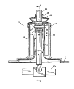
Fig. 1 is a sectional elevational view of a dual ratio
transmission shifter assembly in accordance with this
invention.
Fig. 2 is a sectional elevational view taken a;ong
line 2-2 of Fig. 1.
DETAILED DESC~IPTION OF THE PREFERRED EMBODIME~T
- Reerring now to the drawings, there is illust-ated a
transmission shifter assembly, indicated generally at 10,
in accordance with the invention. The shifter asse.~bly 10
is mounted on a housing 11 of the transmission. The
transmission itself is conventional in the art. Three
elongated shift rails 12a, 12b, and 12c are disposed within
the transmission housing 11. Each of the shif~ rails 12a,
12b, and 12c is associated with a gear engaging mechanism
(not shown) of the transmission. The gear engaging
mechanisms are adapted to selectively engage and connect
various gears within the transmission to provide a
plurality of available gear ratios between input and output
1 3 1 7 1 9~
shafts (neither shown) in a conventional manner. When the
shift rails 12a, 12b, and 12c are in their illustrated
neutral positions, the respective gear engaging mechanisms
disconnect the transmis~ion gears from one another, and no
power is transmitted through the transmission. However, as
will be de~cribed in greater detail below, the shir~er
assembly 10 can selectively move the shift rails 12a, 12b,
and 12c both forwardly and rearwardly from their neutral
positions (left and right when viewing Fig. 1) so as to
cause the transmission to provide a desired one of a
plurality of gear ratios for use between the input znd
output shafts of the transmission.
The shifter assembly 10 includes a tower 13 ha~Jing a
base which is secured to the transmission housing 11 by any
conventional means, such as a plurality of threaded
fasteners (not shown~. As best shown in Fig. 2, the tower
13 is hollow and has a pair of threaded apertures l~a
formed therethrough. The apertures 13a are aligned with
one another on opposite sides of the tower 13 near the base
thereof. An axis 15 (the shifting axis, as will be
explained below) is defined by the apertures 13a.
support member 16 is threaded within each of the ape-tures
13a. ~ach of the support members 16 terminates in a
cylindrical trunnion 16a extending within the tower 13
along the shifting axis 15. An annular ~earing 17 is
mounted about each of the cylindrical trunnions 16a.
A shift yoke, indicated generally at 20, is mounted
within the tower 13 for pivoting movement ahout the
shifting axis 15. As best shown in Fig. 2, the yoke 20
includes a pair of lower legs 21, each of which has an
aperture 22 formed therethrough. The apertures 22 are
sized to receive the annular bearings 17 therein such that
the yoke 20 is pivotably supported within the tower 13 for
movement about the shifting axis 15. As ~est shown in Fig.
1, the yoke 20 further includes a pair of upper legs 23.
An aperture 25 is formed through each of the upper legs 23
1 3 1 7 1 ~
which are aligned so as to define an axis 26 therethrough
(the selecting axis, as will be explained below). The
selecting axis 26 is perpendicular to the shifting axis 15
and is located near an upper end of the tower 13. A pivot
pin 27 extends through the apertures 25 bet~een the upper
legs 23 of the yoke 20O Between the upper legs 23, a pair
of annular bearings 28 are disposed about the pivot pin 27.
A shift lever 30 e~tends vertically through the
shifter assembly 10. An aperture 31 is formed through the
shift lever 30. The pivot pin 27 and the annular bearings
28 are received within the aperture 31 such that the shift
lever 30 is mounted for pivoting movement relative to the
yoke 20 about the selecting axis 26. The upper end of the
shift lever 30 extends upwardly out of tlle tower 13 to a
location where it can easily be grasped and manipulated by
an operator, as will be discussed below. A flexible boot
32 is connected between the tower 13 and the shift lever
30. The lower end of the boot 32 is attached about th
upper end of the tower 13 by a band 33, while the upper end
of the boot 32 is attached about thP shift lever 30 by a
band 35. The boot 32 prevents dirt or other contaminants
to ent~r within the tower 13, while permitting unrestricted
movement of the shift lever 30. The lower end of the shift
lever 30 extends downwardly through the tower 13 into an
area de~ined by aligned notches formed in each o the shift
rails 12a, 12b, and 12c.
As shown in Fig. 2, a boss 40 is formed on one of the
lower legs 21 of the yoke 20. The boss 40 extends
outwardly from the leg 21 and terminates in a generally
flat end surface having a small recess 41 formed in the
center thereof. The boss 40 is aligned with an aperture 42
formed through the tower 13. A neutral start switch
assembly 43 is retained within the aperture 42. The
neutral start switch assembly 43 is conventional in the art
and includes a mova~le plunger 45 adapted to engage the end
surface of the boss 40. As will be described in grea~er
1 3 1 7 1 ~
detail below, the neutral start switch assembly 43
generates electrical signals in response to movement of the
yoke 20.
To operate the transmission, the upper end of the
shift lever 30 is initially moved such that it is pivoted
about the upper selecting axis 26. As described above,
such movement of the shift lever 30 occurs without movement
of the yoke 20. Consequently, the yoke 20 remains in its
illustrated neutral position, wherein the plunger 45 of the
neutral start switch assembly 43 is received in th recess
41 formed in the end surface of the boss 40. By mo~ing the
shift lever 30 about the selecting axis 26, the lower end
thereof can be moved into a single desired one of the
aligned notches formed in the shift rails 12a, 12b, and
12c. This selecting movement of the shift lever 30 does
not move any of the shift rails 12a, 12b, and 12c out of
their central neutral positions, but rather selects one of
the shift rails 12a, 12b, and 12C for such movement~
As is well known, it is desirable to prevent a vehicle
engine from being started when the transmission is not in
neutral. So long as the plunger 45 of the neutral start
switch assembly remains in the recess 41 of the boss 40,
the neutral start switch assembly 43 yenerates an
electrical signal indicating that all of the gears of the
transmission are disengaged such that no power can be
transmitted therethrough, i.e., that the transmission is in
neutral. This signal is used by a conventional ignition
interlock (not shown) or other means to enable the engine
of the vehicle to be started.
To engage the transmission, the selected one of the
shift rails 12a, 12b, and 12c can be moved out of its
central neutral position by moving the upper end of the
shift lever 30 about the shifting axis 15~ As described
above, such movement of the shift lever 30 also causes
pivoting movement of the yoke 20 out of its neutral
position~ The movement of the yoke 20 causes the recess 41
1 3 1 7 1 q(3
on the boss 40 to move relative to the plunger 45 of the
neutral start switch assembly 43. As a result, the plungPr
45 is retracted within the neutral start switch assembly
43. Such retraction causes the neutral start switch
assembly 43 to gener te an electrical signal indicating
that some of the gears of the transmission are engaged,
i.e., that the transmission is not in neutral. This signal
is used by the ignition interlock to prevent the engine of
the vehicle from being started. Thus, it can be seen that
the appropriate electrical signals are generated by the
neutral start switch assembly 43 by sensing the movement of
the yoke 20.
The relative orientation of the shifting axis 15 and
the selecting axis 26 as descxibed above is advantageous.
By locating the shifting axis 15 near the lower end of the
tower 13 and relatively close to the shift rails 12a, 12b,
and 12c, a mechanical advantage is provided to the operator
when moving the shift lever 30 about the shifting axis 15.
Such mechanical advantage reduces the amount of effort
required to be exerted to move the selected one of the
shift rails 12a, 12b, and 12c than if the shifting axis 15
were disposed further upwardly within the tower 13. This
is important in accounting for comfort or "feel" of the
shifter assembly 10 during the shifting process.
Since the selecting axis 26 is located above the
shifting axis 15 (i.e., farther away from the shift rails
12a, 12b, and 12c than the shifting axis 15), the same
mechanical advantage does not apply to movement of the
shift lever 30 about the selecting axis 26. However, the
lack of such mechanical advantage is of no conse~uence,
since the lower end of the shift lever 30 does not engage
or move any components when it is moved about the selecting
axis 26. Fur~hermore, b~cause the selecting axis 26 is
located farther away from the shift rails 12a, 12b, and 12c
than the shifting axis 15, the lower end of the shift lever
30 travels farther when the upper end of the shift lever 30
~31719~
is moved a predetermined distance about the selecting axis
26 than when the upper end of the shift lever 30 is moved
about the shifting axis 15. Thus, the operator does not
have to move the upper end of the shift lever 30 as far as
would otherwise be required in order to select one of the
shift rails 12a, 12b, and 12c for use, thereby providing a
more convenient shift pattern~
In accordance with the provisions of the patent
statutes, the principle and mode of operation of this
invention have been explained and illustrated in its
preferred embodiment. However, it must be understood that
the invention may be practiced otherwise than as
specifically explained and illustrated without depa- ing
from its spirit or scope.