Note: Descriptions are shown in the official language in which they were submitted.
1 31 7206
-- 1 --
This invention relates to a very simple and
convenient immunological detecting method ~or detecting a
component of a biological system, above all for immuno-
logical diagnosis, and to a device for immunological
detection. More specificallyr this invention relates to a
method and a device for detecting an antigen or an anti-
body protein on the basis of an antigen-antibody reaction
on a reflecting substrate.
Immunological diagnosis has been performed by
utilizing an antigen-antibody reaction which is a very
specif ic biochemical reaction. Radioimmunoassay ~RIA~,
enzyme immunoassay (EIA), fluorescent immunoassay (FIA)
and latex agglutination settling analysis ~LSA), for
example, are known and used in practice as specific
methods o the immunological diagnosis. Tbese methods
still have technical problems to be solved. RIA has very
high detection sensitivity, but require~ special facili-
ties for handling radioactive elements. EIA requires a
long period o~ time (usually several hours to one day) for
the completion of detection. FIA does not have su~ficient
detection sensitivity. LSA canrlot avoid a non-specific
agglutination reaction, and has low reliability in de~ect-
ing trace components.
On the other hand, an ellipsometric method was
proposed ln which an increase in the thickness of a pro-
tein layer which occurs with the progress of an antigen-
antibody reaction on a solid substrate is detected by
using ellptic polarized light (British Patent 1,479,661).
This method also requires an expensive device and much
expertise is required for measuring the protein film
thickness. There has also been proposed a m~thod of
detecting an antigen-antibody reaction ~imply with the
unaided eye without using such an expensive device. For
example, it is a method which comprises adsorbing and
1 31 7206
- 2 -
fixing an antibody ~or an antigen~ on and to khe surface
of gold particles deposited on a solid substrate, and
visually observing changes in the color of the reflected
light which occur as a result of an increase in the
thickness of a layer of an immobilized antibody (or
antigen) by an an~igen-antibody reaction (U. S. Patent
3~979~184)o According to this method, the color of the
complex of gold and the protein film on the solid sub-
strate certainly changes with the antigen/antibody re-
action. Since, however, the change is only slight frombrown to dark brown and very obscure, the evaluation of
the antigen-antibody reaction may possibly depend greatly
upon the expertise of the testing personnel.
When an antigen or antibody is fixed to a di-
electric layer formed on a highly light reflecting sub-
strate such as a metallic chromium or tantalium substrate
and an antigen-antibody reaction is carried out on its
surface as shown, for examplel by Langmuir and Blodgett,
Physical Review, vol. 51, pages 964-978 (1937) or Vroman,
Thromb. ~iath. Haemorrhag., vol. 10, 455-493 ~1964~, the
difference in refractive index between antigen or antibody
and the air is very small and the reflectance on the
surface of the antigen or antibody is as low as 5% at an
incidence angle of 0 to 60. On the other hand, the
proportion of light reflected from the metallic substrate
and coming back to the surface of the protein is higher
than 50%. Accordingly, it is difficult to detect the
interference color on the surface of the device. ~o
discriminate this interference color with good ef~iciency,
it is necessary to adjust the angle of reflection of light
on th surface of the device to at least 50 to 70, and it
is difficult to detect with the unaided eye. Another
proposal for solving this problem (UO S. Patent NoO
4,558r012~ states that light interference occurs ef-
ficiently by providing two types of dielectric layers on anon~metallic substrate which does not so much reflect
1 31 7206
-- 3 --
light, and making the amount of light reflected from the
surface of the substrate nearly e~ual to that of light
reflected from the surface of the dielectric layers.
However, substrates meeting such conditions are limited to
s those which are colored or have high light transmitting
property, and those having a high reflectance cannot be
used. The colored substrates affect the interference
color on the surface of the device and make the detection
difficult. With the substrates having a high light trans-
10 mittance, the color of the device becomes dark and ligbt
interference which gives a brilliant visible light color
does not easily occur. If a substrate having a relatively
high surface reflectance o 60 to 90~ is used, it is
essential to provide a plurality of dielectric layers
15 havin~ different refractive indices, and the process of
building the device becomes complex.
The present inventors have made extensive in-
vestigations in order to develop a device for detecting a
component of a biological system, which is ree from the
2Q aforesaid problems of the prior art and permits easy and
highly sensitive detection of the biological component
with the unaided eyed. These investigations have now led
to the discovery that if a thin film of fine metallic
particles is provided on the surface of the device after
25 reacting a detecting substance with a substance to be
detected, optionally after the surface is subjected to a
contrast enhancement treatment, the amount of light re-
flected from the surface of the substrate is balanced with
the amount of the light reflected from the sur~ace of the
30 device within ranges where these amounts are large.
According to this invention, there is provided a
method for detecting a component of a biological 5yStemt
B which comprises ~-contacting a device for thP detection
of a biological component composed of a }ight reflecting
35 substrate SI) substantially free from diffused reflection,
a light interference layer ~II) formed on the substrate
131720~)
67566-1052
(I), and a layer ~III) of a subs*ance for detecting said
biological component provided a~ least in a region on the layer
~II), with a solution presumed to contain the bioloyical component
to be detec~ed, then forming a light-transmitting reflecting layer
~IV) on its sur~ace and thereafter detecting the colcx of light
interference or the brightness of the reflected light on the
surface of the device.
The device may be subjected to a contrast enhancement
treatment and the incident angle at which the light-transmitting
~0 reflecting layer is exposed to light is preferably 0 to 50
degrees.
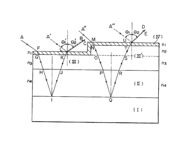
In the accompanying drawinys:-
Figure 1 is a view for explaining the concept of light
interference of a biological assay sample; Figure 2 is a side
elevation showing an example of building a device with
multiantibodies for detecting plural biological components; and
Figures 3 and 4 are sectional views similar to Figure 1 but
illustrating different embodiments of the invention.
In the drawings, I represents a light reflecting
substrQte; II, a light interference layer; III, a layer of a
substance for detecting a biological component; III', a complex
layer formed by reaction of the layer III with ~he biological
component to be detected; IV, a light transmitting reflecting
layer; nl, the refractive index of the light-transmitting
reflecting layer; n2, the refractive index of the biologi~al
component to be detected; n3, the refractive index of the
substance for detecting the biological component; n~, the
refractive index of the light interference layer; ~1 and ~1
angles of incidence; and ~ and ~2' reflection angles.
The light reflecting substrate (I) used in thls
invention may be made of an ordinary metal such as iron, nickel,
cobalt, zinc, titanium and bismuth, an alloy thereof, or a metal
having a high reflectance such as gold, silver, copper and
aluminum. The substrate (I) may be made of such a material itself
1 31 720h
67566-105~
in a plate form, or may be made by formin~ a thin layer o~ su~h
metals or ~lloys, either slnyle or to improve adhesion to ~he
~ubstrate, in
~a
~, ,,,1
,
1 31 7206
combination, by vapor deposition or sputtering on a solid
substrate such as a glass plate or a plastic plate. The
reflectance of this layer i8 at least 50%, preferably at
least 70%, when white light is allowed to fall upon it at
an incidence angle of 0 to 50 degrees, preferably 0 to 30
degrees.
The light interference layer (II) used in this
invention should meet the following requirements (1) to
~3). (1~ rt should not have substantial reflecting
characteristics to visible light ~wavelength 300 to 800
nm). ~2) The thickness and refractive index of the light
interference layer (II) should be controlled such that an
increase in the thickness of the layer ~III) of a sub-
stance for de~ecting a biological component with the
biological component detecting reaction appears as a
change in interference color. ~3) Its surface preferably
has su~ficient affinity for the layer ~III).
The lig~t interference layer (II) may be made of
an organic or inorganic material. The organic material
may be any which does not substantially have reflecting or
absorbing characterisics in a visible light region (300 to
800 nm~ and are film-forming. Preferably, it may be an
organic material which permits control of its film thick-
n~ss to the order of 50 to 100 ~ so as to induce efficient
changes in the color of light interference with an in-
crease in the thickness of a protein film by a biological
component detecting reaction such as an antigen-antibody
reaction to be described in detail hereinafter~ Such
organic ma~erials may, for example, be compounds capable
of forming a stable condensed monomolecular film on a
water surface; such as long-chain carboxylic acids and
metal salts and esters thereof, and materials capable of
forming films having a thickness of not more than 2rO00
by coating or vapor deposition. Specific ex~mples of the
former include long-chain saturated and unsaturated carb-
oxylic acids such as palmitic acid, stearic acid,
1 31 72~6
-- 6 --
lignoceric acid, oleic acid and omega-tricosanoic acid,
esters thereof, and salts thereof with mono- to tri-valent
metals. Examples of the latter include vinyl polymers
such as polytmethyl ~meth)acrylate], polystyrene, poly-
(meth~acrylonitrile and polyvinyl chloride; polyolefinssuch as polyethylene, polypropylene and poly-4-methyl-
pe~tene-l; and condensation polymers such as polyamides
and polyesters. Since these substances inducs effective
light interference according to their refractive indices,
their film thickness is controlled. The inorganic mate-
rial which may constitute the light interference layer
should likewise have no reflection and no absorption in
the visihle light region, and the thickness of a film
thereof should be controlled to the order of 50 to 100 ~.
Examples of the inorganic material having such properties
include metal oxides such a~ silicon oxlde, aluminum
oxide, tin oxide, lead oxide, tungsten oxide, magnesium
oxide, cobalt oxide, molybdenum oxide, titanium oxide,
zirconium oxide, zinc oxide and tantalum oxide: metal
fluorides such as calcium fluoride, magnesium fluoride and
lithium fluoride; intermetallic compounds such as gallium-
arsenic; and silicon nitride. Such a material may be
formed into a film of the desired thickness according to
its refractive index by vapor deposition or sputtering and
provided as the light interference layer ~II) on the
reflecting substrate (I).
The surface of the light interference layer ~II)
should also be required to have affinity for substances
~such as antigens or antibodies) for detecting biological
components in the layer (III). For this purpose, the
surface of the light interference layer (II~ may be
treated by a hydrophobizing agent such as an alkyl- or
aryl-silane, or chemically modified by a reactive compound
which can chemically fix the sub~tance for the detection
of biological component to interference layer (II). The
hydrophobizing agent layer and the reactive compound
.
.
1317206
-- 7 --
layer are shown as/layer (P) in Figure 3 (a sectional view
similar to Figure ~O . The hydrophobizing agent layer is
essential when the light interference layer is composed of
an inorganic material.
Examples of the alkyl- or aryl-silane as the
hydrophobizing agent are C12-C20 alkyltrichlorosilanes
such as octadecyltrichlorosilane, mono-, di- or tri-alkoxy-
silanes, dimethyldichlorosilane, dimethylphenylchloro-
silane and methyldiphenylchlorosilane.
The treatment of forming the reactive interlayer
is carried out, as required, in order to increase the
affinity of the surface of the light interference layer
(Il) for the biological component detecting substance in
the layer (III).
In most known devices for detecting an immuno-
logical reaction utilizing light interference, antigen
molecules are fi~ed, and there is no example in which an
antibody is fixed in such devices. Since generally there
are many recognition sites in antigen molecules, the
alignment of the antigen molecules is not of much signi-
ficance in fixing them. On the other hand, since the
recognition sites of antibody molecules are strictly
limited, they have to be arranged so that the recognition
sites are effectively exposed to the surface of the de-
tectin~ device. By an ordinary physical adsorption methodor a chemical fixing method, it is extremely difficult to
fix antibody molecules without impairing their activity.
In view of the above background, the present
inventors have extensively worked on a method and a device
for detectlng an antigen-antibody reaction with good
sensitivity by a simple procedure within a short period of
time, and consequently found that an immunological detect-
ing device of high sensitivity and free from delamination
can be obtained by using a device consisting of a iyht
reflecting substrate and a light interference layer having
an optimized thickness and an optimized refractive index
. . , -
1317206
-- 8 --
and chemically bonding an antibody layer to the surface of
the light-interference layer selectively at sites other
than the recognition sites of the antibody.
~s one embodiment, the present invention pro-
vides a simple immunological detecting device comprising alight reflecting substrate (I) substantially ~ree from
diffused reflection, a light interference layer (II)
laminated to the surface of the substrate (I)~ a reactive
interlayer (P) formed on the layer (II) and camposed of a
compound capable of ~electively reacting the carboxyl
group or thiol group contained in antiyen or antibody
molecules or fragmented antibody molecules mainly by pH
adjustment, and a layer ~III) of an antigen substance
and/or an antibody protein composed substantially of a
monomolecular layer formed on the interlayer ~P~; and a
method of immunological detection utilizing the device.
The compound capable of reacting with the carb-
oxyl group of the protein is preferably one which contains
o
functional groups such as CH2/CH-, 0\~ or -NH2 in the
O
molecule and can be fixed at a high density to the light
interference layer. It ~ay be a low-molecular-weight or
high-molecular-weight compound. Specific examples of the
low-molecular-weight compounds are
/ \
CH2-cH-~nH2n+l (n=10~30) and CmH2m+l-N~2 ~m 16-30)-
Specific examples of the high-molecular-weight compound
are
,16 33 R
~CH2CH-CH-CH~ ~ ~CH2C~ [R=CH3, H3
C= ~ ~ =C COOCH2C~-CH2
O O
1 31 7206
g
~CH2CH~ , polyethyleneimine and ~C~2CH~ .
NH~
N}~2
Compounds capable of reacting with the thiol group ~S~) of
the protein are, for example,
O O
\N-~CH2 ~ N~ ~ (when this compound is used, the
t~ n
O O
substrate is preferably pre-treated with, for example~
n
H N~CH~Si~OR) 31 CN CZH2Z+1
CQH2Q~lNHCCH2X lX=Br, I; ~=integer of 10-30),
CyH2y~lNCO ~y=integer of 10-3Q) and
CH3
CH2-C-COO~CH ~ i(OR)3 (R=Cl_3 alkyl).
1~ N-substituted maleimide is most prefera~ly used. Many of
the above compounds can react not only with the carboxyl
or thiol groups in the protein but also with the amino
groups in it. Hence, the protein fixing reaction should
be carried out by adjusting the pH of the reaction system.
~he preferred p~ range is 3 to 5 f or the reaction with the
carboxyl groups, and 4 to 6 for ~he reaction with ~he
thiol groupsO
Such a compound is formed as a thin film layer
(P) on the light interference layer ~II). The thickness
of this film should be controlled such that the i~ter-
ference color of the en~ire lay~r above the light re-
flecting substrate should be within the visible lîght
region~ Such a film thickness is selected from 25 to 5Q00
~, pre~erably 30 to 3,000 R.
131720h
-- 10 --
The thickness of the light interference layer
(II) should be selected such that when the incidence
angles ~1 and ~'1 are 0 to 50 degrees, the light path
differences of ~he incident ligh~ at the device as shown
in Figure 1.
Light path difference -1:
nlx(FG+KL~ + n3x(G~KJ) + n4 (
Light path difference -2:
nlx(MN+UT) + n2x~NO~ST) ~ n3x(OP+RS) +
n4x~PQ+QR)
become the product of the wavelengths of incident lights
multiplied by integers. Furthermore, for the discrimi-
nation of an antigen-antibody reaction site, it is con-
venient that the light path difference -1 differs from the
light path difference -2. For example, the optical thick-
ness of the light interference layer (II) should be con-
trolled to about 500 to S,000 ~, preferably 700 to 3,000
R, when this layer has a refractive index of 1.4 to 2Ø
Examples of such an accurate film thickness controlling
method are the Langmuir-Blodgett method ~a monomolecular
film on a water surface is acumulated on a solid sub-
strate), the spin coat method, the vapor deposition method
and the sputtering me hod.
The biological component detecting substance in
the layer (III) to be fixed to the light interference
layer tII) may preferably be an~ibodies, antigens, etc.
which are involved in immunological reactions, nucleic
acids, viruses, bacteria, etc. Of these, the antigens and
antibodies are preferred.
Examples of the antigens are immunQglobulins
such as IgG, IgA~ IgE and IgM, human chorionic gonado-
tropin (HCG), and carcinoembryonic antigen (CEA)~ As the
antibodies, polyclonal or monoclonal antibodies to these
antigens are used.
.
1 31 7206
-- 11
These antigens or antibodies may be fixd to the
surface of the light interference layer ~II) lthe term
"light interference layer ~II)", to be used hereinbelow,
means one optionally having the aforesaid hydrophobiziny
5 agent layer or reac~ive interlayer IP) on its surface~ by
immersing the device in an aqueous solution o~ an antigen
or antibody for 0.5 to 20 hours, and then fully washing it
with water to remove the antigen ~or antibody) molecules
physically adhered to it. As a resu~t of this adsorption
treatment, the antigen (or antibody~ is fixed onto the
light interference layer (II) as a monomolecular layer
tIII).
On~ or more kinds of antibodies and/or an~igens
may be adsorbed on the light i~terference layer ~II). To
lS fix two or more kinds of antibodies ~or antigens), the
depth of chips ~I + II) composed of the reflecting sub-
strate tI) and the light interference layer (II) formed
thereon, to which they are immersed in solutions ~X, Y and
Z) of the antibodies ~or antiyens~, is progressively
increased. By so doing, it i~ po~sible to fix a plurality
of antibodies ~or antigens) onto the same chip as a mono-
molecular layer since generally, another antibody (or
antigen) i8 not adsorbed on that part to which one anti-
body ~or antigen) has adheredO This procedure enables
expensive monoclonal antibodies, for example, to be ef-
fectively fixed.
According to another preferred embodiment of
this invention, the antibody protein layer ~III) can be
fixed to the light interference layer (II) in a form
oriented so that it does not lose activity, by spreading
(1~ a monomolecular film of a long-chain fa~ty acid having
24 to 32 carbon atoms, a salt thereof with a polyvalent
metal and/or an ester thereof or (2~ a monomolecular film
of a polyvalent metal salt of a long-chain fatty acid
having 14 to 23 carbon atoms and~or an ester of the long
chain ~a~ty acid on an aqueous phase surface, and
1 3 1 7206
contac~ing a water-soluble antibody protein dissolved in
the aqueous phase to form an antibody monomolecular mixed
film on the interface of the aqueous phase, and laminating
the complex on the light interference layer (II).
The antibody protein generically denotes a
water-soluble protein which can induce an antigen-antibody
reaction, and contains an antigen recognition site (Fab
for short) and a hydrophobic terminal site (Fc for ~short).
Specific examples of the antibody protein are
immunoglobulins G (abbreviated IgG~, IgE, IgM and anti-
bodies to them, human chorionic gonadotropin ~HCG) anti-
body and carcinoembryonic antigen (CEA) antibody.
In fixing these antibody proteins, care should
be taken not to denature the Fab portion. In conventional
fixing procedures by a chemical reaction, the Fab portion
is also involved in the reaction to cause a decrease in
the activity of the antibody protein. According to the
above method in accordance with this invention, the anti-
body protein is incorporated at a high density into themonomolecular film while hydrophobically interacting at
the Fc site or adsorbed on and fixed to the monomolecular
film while maintaining high immunological activity.
The monomolecular film preferably remains a
condensed monomolecular film on a solid on a water surface
and does not substantially dissolve in water. Example~ of
the long-chain fatty acid having 24 to 32 carbon atoms,
its polyvalent metal salt and/or its ester include
lignocerl~ acid (C23H47COOH), cerotic acid ~C25~51COOH~,
montan acid (C27H55COOH), melissic acid (C29H59COOH),
lacceronic acid (C31H63COOH3, polyvalent metal salts of
long-chain fatty acids represented by the ~ormula
Cn~2n+lCOOM ~n=23 - 21, M=a polyvalent metal ion such as
alkaline earth metals, cadmium and aluminum), and e~ters
of these fatty acids with methanol or ethanol7 Example~
of the polyvalent metal salts of long-chain fatty acids
1 31 7206
- 13 -
havin~ 14 to 22 carbon atoms and/or the esters of these
fatty acids are salts of polyvalent metals such as
alkaline earth metals, cadmium, and aluminum with fatty
acids such as myristic acid ~Cl3H27COOH), palmitic acid
(Cl5H3lCOOH), stearic acid (Cl7H35COOH), ara~hidic acid
(ClgH39COOH) and behenic acid (C2lH43COOH), and esters of
these fatty acids with methanol or ethanol.
The above compound (l) or (2), either as a
carboxylic acid or its ester, is dissolved in an organic
solvent such as benzene or chloroform to form a solution
having a concentration of 0.5 to 1~5 millimole~liter~
When the solution is spread on the surface of distilled
water or an aqueous solution containing a polyvalent metal
salt Isuch as barium chloride, cadmium chloride or
aluminum chloride), the monomolecular film used in this
invention is formed. The monomolecular film is then
compressed so that its surface pressure becomes l to 20
mN/m, and under these compressing conditions~ the antibody
protein is injected into the aqueous phase below the film.
By keeping the antibody protein and the monomolecular film
on the water surface in contact with each other for a
predetermined period of time (usually 30 minutes to l
hour), complexing of the protein and the monomolecular
film is completed. At this time, the complex film of the
antibody protein and the monomolecular film is again
compressed to a surface pressure of 10 to 30 mN~m, and
laminated to the surface of the light interference layer
(II) by the Langmuir-Blodgett or the horizontal lifting
method. One or more layers of such complex film can be
laminated.
The amount of the antibody protein fixed to the
light interference layer is calculated from the ratio of
the water surface area of the spread film to the area of
the light interference layer at the time of lamination and
the intensity of the UV absorption spectrum of the film.
At least a region of the detection device of
1 31 720(')
- 14 -
this invention in which the layer (III) is ixed is
brought into contact with an assay sample to be determined
to contain a biological substance such as an antigen (or
antibody) to thereby allow a biological reaction to take
place. Conseguently, a layer ~III') of a complex of the
biological component to be detected and the biological
component detecting substance is formed on at least a
region tthe region where the reaction has taken place) on
the layer 5III) (the device in this condition is referred
to as a "detection structure").
Preferably, the biological component to be
detec~ed is selected so that as a result of complexing, an
increase in its optical thickness becomes more than S R,
preferably more than 10 ~, but less than 500 R, preferably
less than 300 ~. Antigens and antibodies are preferred as
such a component.
The present invention is applicable even when
the biological component to be detected is the same as the
substance of the biological component detecting substance
layer (III). For example, if it is an antigen, an anti-
body to the biological component ~antigen) is u~ed as an
intermediary substance. By mixing this antibody with a
solution suspected of containing the biological component
o be detected, and contacting the mixture with the
device, the antibody reacts competitively with the bio-
logical component in the solution and the biological
component in the device. The advantage of this method is
that the above antibody subjected to a contrast enhance~
ment treatment in advance can be used, and this can
increase detection sensitivity. Furthermore, the activity
of the device is easy to retain be ause it is an antigen
which is to be fixed to the device and not an antibody
that is more susceptible to deactivation than antigen in
fixation~
In the detecting method of this invention, a
light~transmitting reflecting layer ~IV) is then formed on
1 31 7206
- 15 -
the surfaces of the layers ~III') and ~III). Formation of
the layer ~IY) permits very easy distinction between the
portion where the biological reaction has taken place
l(III')] and the other portion where no biological reac-
tion has taken place [~III)] on the detection structure.
Preferably, the light-transmitting reflecting
layer (IV) is a thin layer of a metal, preferably a noble
metal, formed by a vapor deposition method, other physical
vapor deposition methods, a colloidal particle coating
method, etc. The colloidal particle coating method is
preferred because of its simplicity of operation. Metal
colloids which exist stably in water, can be adsorbed on,
or react with, proteins, and have a particle diameter of
10 to 200 ~, preferably 30 to 150 R, can be used in this
method. Specific examples include dispersions of fine
particles of gold, platinum, silver, palladium, ruthenium~
aluminum, copper, nickel, iron, eto., either alone or
together with dispersion stabilizers, in water. Gold
colloid is most suitably used in this invention. These
metal colloids form a high reflectance layer on the sur-
face of the detection structure and strikingly i~proves
the visual determinability of the device.
To increase visual determinability further by
gold colloid, the conditions for coating gold colloids may
be controlled by considering the isoelectric points of
proteins adhering to the device. The gold colloid has the
property of being adsorbed on a protein at a pH slightly
(less than 1.0, preferably about 0.5) higher than the
isoelectric point of the protein. If the gold colloid is
adsorbed at a pH about 0.5 higher than the iRoelectric
point of a protein to be detected and lower than, or more
than 1.0 higher than~ the isoelectric point of a detecting
protein, only the protein is colored by the metal colloid
adsorbed thereon, and the other portion is not colored (or
hardly coloredl, and the presence of the protein can be
determined very easily.
1 31 7206
- 16 -
Generally, since the concentration of the pro-
tein to be detected is low, it is preferred from the
standpoint of detection sensitivity to operate so that the
gold colloid is adsorbed on the protein to be detected.
The light-transmitting reflecting layer SIV)
formed in the above manner has a thickness of 30 to 300 R,
preferably 50 to 100 ~, and its light reflectance is 10 to
40%, preferably 20 to 30%, at an incidenc~ angle of n to
50 degrees.
As one modification, it is possible to first
subject the surface of the layer (III') of the detection
structure to a contrast enhancemen~ treatment, and then
provide the light-transmitting reflecting layer (IV~. In
this treatment, a substance capable of reacting with the
substance to be detected, with which the substance in the
biological component detecting substance layer (III)
reacts, at a site different from the site at which the
substance ~o be detected reacts may be used as a contrast
enhancement agent. The molecular size of the contrast
enhancement agent is selected so that after reaction with
the substance to be reacted, the light interference color
of the device varies in a visible light region. As a
specific example, its thickness is 30 to 200 g, preferably
50 to 150 ~O Its molecular sectional area is not par
ticularly restricted, but generally 0.05 to 3 micrometers,
preferably 0.1 to 1 micrometer. Specific examples include
secondary antibodies, enzyme-labelled secondary anti-
bodies, secondary antibodies fixed to emulæions and
secondary antibodies fixed to latices~ When the contrast
enhancement agent is added after the biological component
detecting substance layer (III) has reacted, or is react-
ing, with the substance to be detected on the device, a
layer (Q~ of the contrast enhancement agent is formed on
the layer (III'~ as shown in ~igure 4 ~sectional view),
and these layers as a whole increase in optical thickness
to increase the detection sensitivity of the device.
-
1 31 72~')
- 17 -
When, for example, white light i~ allowed to
fall upon the detection structure formed as above by u~ing
the device of this invention at an incidence angle of, for
example t 0 to 50 degrees, the site where the antigen-
antibody reaction has taken place can be clearly detectedby the change in the interference color of the reflected
light. Furthemore, when monochromatic light is allowed to
fall, the site of the antigen-antibody reaction can be
detected by distinguishing the brightness and darkness of
the reflected light. The sensitivity of its detection is
much higher than that obtained with conventional devices
and methods. An antibody (or antigen) in a concentration
of 10 5 to 10 12 mole/liter can be clearly detected by
visual inspection within several minutes to 30 minutes.
The requisites used in the detecting method of
this invention are all handy and simple. These requisites
can therefore be offered to the consumers in the form of a
kit composed of, for example, tl) a pack of various types
of device described above and (2) a pack of metal colloid,
and optionally (3) a pack of a contrast enhancement agent.
If it is desired to perform quantitative deter-
mination at higher detection sensitivity in the above
detection, it is possible to detect changes in light
interference as the amount of change in color difference.
Generally, the color difference is typically represented
by the following e~uation ~aE*ab) defined by tristimulus
values X, Y and Z of the visible spectrum of the calori~
metric standard observer stipulated by International
Committee on Illumination (ICI).
~E*ab = ~ tQL*)2~Aa*)+~ab*)2
wherein L*=116(~yo)l/3 16,
a*=5001(x )1/3 _ (Y )1/3]
1 31 720G
- 18 -
b*=~oo [ ~y ) 1/3 _ ~Z )1/33
XO~ YO and ~O are tristimulus values of an
illuminating light source, and X, Y and Z aee
tristimulus values of the spectrum of the
S calorimetric standard observer stipulated by
International Committee on Illumination ~1931).
Among the color components constituting the color dif-
: ferences ~E*ab, ~L*, ~a* and ~b* respectively represent
the amount of change of the brightness ~L*~ o color, the
amount of change of a red color component (a*) and the
amount of change of a yellow color component (b*). ~c-
: cording to the standards of ICI, an absolute value of the
color difference (~E*ab) of 0 to 0.5 means that determi-
nation of the color difference by visual insp~ction is
impossible or the color difference is very slight; an
absolute value of the color difference of l.Q to 6~0 means
that the color difference by visual observation can be
determined; an absolute value of the color difference of
6.0 to 12.0 means that the color difference is v~ry re-
20 markable; and an absolute value of the color diference ofmore than 12.0 means that the color is of another color
series. Hence, when in the detecting methvd of this
invention, the color difference, aE*ab, betweQn the re-
acted site ~III') and the unreacted site (III~ is 0.1 to
25 1.0, more strictly 0.1 to 0.5, distinction by visual
: inspection is difficult. In this case, it is desirable to
perform quantitative distinction by a color difference
photometer. Systems utilizing other conversion equations
for color difference may of course be used.
To increase the luminance of the light inter-
ference color, it is preferred to use an incidence ligh~
source having the strongest possible intensity. If,
however, the intensity of the incident light is too
1 31 720~
~ 19 -
strong, direct visual inspection becomes impossible. When
a color difference photometer is used, such physiological
restrictions on the light intensity are obvia~ed and
therefore desirable light intensities can be used.
Detection can be performed with the highest
sensitivity by designing the device such that the angle of
incident light on the detection structure or the angle
between the detection structure and a light-receiving
section in a color difference photometer is optimal, or it
can be adjusted so as to provide such an optimal angle
difference.
Since the color difference by the interference
light can be displayed digitally by the color difference
photometer, discrimination does not differ among the
testing persons, and the detection device can be handled
with rapidity, simplicity and convenience. Preferably,
the color difference photometer includes a light source or
a jig for diffusing and reflecting or radiating the in-
cident light, such as a bulb for multiple light reflection
and a light diffusion plate, a photovo7taic element, and
a color difference data processor. Specifically, there
may be used a method which comprises separating an inter-
ference spectrum measured on th surface of the detection
structure into tristimulus value components of light and
analyzing them, and a method in which the tristimulus
values of interference light are calculated by also in-
cluding a sensor which measures the reflected light from
the detection structure having sensitivity corresponding
to the spectral sensitivity of the human eye and also
detects the spectral sensitivity of the illuminating light
source. The color difference limit of these color dif-
ference me~ers is +0.15 in terms of AE*ab.
The present invention Pnables a bioloyical
component to be detected (an antigen, an antibody, etc.)
in a low concentration within short periods o~ time with
good sensitivity, simplicity and convenience, and is of
1317206
- 20 -
great significance in practical applications.
The following non-limitative examples illustrate
the present invention more specifically.
EXAMPLE 1
An SiO2 target and a chrome-plated stainless
steel plate as a substrate were set in a chamber in a
high-frequency sputtering device~ and the inside of the
chamber was evacuated to a pressure of 1 x 10 5 torr. Ar
(100%) gas was introduced into the chamber. The p,ressure
Of the inside of the chamber was maintained at 1.0 x 10 3
torr, and glow discharge was performed at 500 W for 13
minutes to form an SiO2 layer having a thickness of B00 ~
on the surface of the chcome-plated substrate. The chrome-
plated stainlesss steel plate having the SiO2 layer with a
thickness of 800 ~ was immersed for 2 hours in a 1.0 x
10 2 wt~% chloroform solution of octadecyltrichlorosilane
to hydrophobize the surface of the SiO2 layer. The plate
was then immersed for 12 hours in an aqueous human IgG
solution (5 x 10 2 mg~ml)~ The resulting device was
immersed for 5 minutes in an aqueous solution of sheep
anti-human IgG ~specific to H and L chains) in a concen-
tration of 5 x 10 2 mg/ml to prepare a detection struc-
ture.
When the detection structure was visually in-
spected from an angle of 70 degrees, the sur~ace vf theSiO2 layer showed an interference color of pale yellow,
the human IgG-adsorbed surface showed an interference
color of yellow, and the anti-human IgG reacted surface
showed an interference color of red. However, when it was
3~ visually inspected from an angle of 30 degrees, it was
very di~ficult to determine ~hese interference colors.
The detection structure was then immersed for 20
minute~ in an aqueous solution of gold colloid having a
particle diameter of S nm ~6.5 x 10¹⁴ particles/ml~ for 20
minutes, wasbed with distilled water, and dried. When the
resulting structure was visually inspected from an angle
.
,
1 31 72û6
- 21 -
of 30 degrees, the sur~ace of the SiO2 layer showed an
interference color of yellow, the human IgG-adsorbed
surface showed an interference color of orange, and the
anti~human Ig~ reacted-surface showed an interference
color of violet. The ease of visual inspection was thus
increased greatly.
EXAMPLE 2
In the same way as in Example ll an SiO2 layer
having a thickness of 800 R was foemed on a chrome-plated
stainless steel plate by the high-frequency sputtering
method. As in Example 1, a human IgG-adsorbed surface and
an anti-human IgG-reacted surface were prepared on the
resulting plate. No interference color was observed in
any of these surfaces at a glancing angle of 0 to 30
degrees.
Then, a thin film of gold having a thickness of
50 to 75 ~ was formed on the resulting pla~e by vapor
deposition, clear interference colors could be viewed.
When the thin gold film was prepared by high-
frequency sputtering, clear interference colors couldlikewise be observed.
COMPARATIVE EXAMPLE 1
Example l was repeated except that a silicon
wafer ~reflectivity for perpendicuIar incident light: 40%~
wa~ used instead of the chrome-plated stainless steel
plate (ibid.: 90%) as a substrate. By immersing the re-
sulting device in a gold colloid solution, the ease of
visual inspection of changes in interference colors in-
creased. But the colors had a darker tone than in the
case o~ using the chrome-plated s~ainless steel substrate,
and visual inspection was more difficult.
EXAMPLE 3
Example l was repeated except that a poly-
ethylene terephthalate film ~thickness 50 microns) having
aluminum vapor-deposited thereon to a ~hickness of l,000 R
was used instead of the chrome plated stainless steel
1 3 1 72~6
- ~2 -
substrate. By immersing the resulting device in a gold
colloid solution, the ease of visual inspection of changes
in interference colors was greatly increased.
EXAMPLES 4-7
In Example 1, an aqueous solution ~pH 9 ad-
justed with NaOH aq.soln~) of each of the metal colloids
shown in Table 2 was used instead of the aqueous g~ld
colloid solution. Specifically, the detection structure
obtained after the antigen-antibody reaction was immersed
in the metal colloid solution for 30 minutes, and the
interference color of the antibody-fixed site and the
interference color of the antigen-antibody reaction site
were compared. In all runs, a clear color difference
could be visually determined. The difference (~Eab)
between the color of the antibody~fixed site and the color
of the antigen-antibody reaction site was measured by a
color difference photometer including a bulb for multiple
light reflection, a photovoltaic element and a color
difference data processor ~self-recording spectral photo-
2~ meter of ~itachi Limited (with an accessory device havinga U-3200J3400 type); measuring wavelength, 380-780 nm;
incidence angle, 6 degrees; visual field angle 10 degrees;
calculated for standard A light]. Clear color differences
were observed as shown in Table 1.
13 1 720G
- 23 -
Table 1
_ . ............. " I
Example Metal Changes in interference
colloid colors after the antigen-
(*l~ antibody reaction ~*2)
. __
Visual deter- Color differ-
minability ence (~Eab)
_. . . . . .....
4 platinum very clear 1.68
silver very clear 1.45
6 palladium very clear 1.24
7 ruthenium very clear 1.10
.. ~
~ *1~: Metal colloids for atomic absorptiometry
(special reagent grade made by Wako Pure Chemicals, Co.,
Ltd.)~
~ *2): Using the anti-human IgG-fixed device,
10 8 M o~ human IgG was detected~
EXAMPLES 8-11
As a ligh~ interference layer, a thin film of
each of the inorganic compounds i~dicated in ~able 2 was
vapor-deposited on a chrome-plated stainless steel sub-
strate. The light interference layer was rea~ed with
octadecyltrichlorosilane in the same way as in Exa~ple 1
and then anti-human IgG antibody was adsorbed and fixed on
and to the treated light interference layer. Using the
resulting device, human IgG was detected in the same way
as in Example 1. The interference colors observed at a
glancing angle ~2) of 60 to 70 degrees are shown in Table
2. When a thin film of gold colloid was coated on the
surface of the detection structure in the same way as in
Example 1, at a glancing angle of 0 to 30 degrees, the
surface looked deep violet, and its visual determinability
increased greatly.
,
1 31 720~
- 24 ~
Table 2
Ex Inorgan1c Change in color After
ample compound before and after treatment
the antigen with gold
. _ _ antibody reaction colloid
Type Film (before treat-
thick- ment with god
ne~s colloid)
. . _ . . . . . . _ . . __
8 silicon 590 yellow orange to deep
dioxide red violet
9 aluminum 650 scarlet to violet deep
oxide violet
10 tin oxide 820 red to blue deep
: violet
11 magnesium 1059 yellow to scarlet deep
fluoride violet
~*) Measured by an ellipsometer ~DVA-361,
Mizoshiri Kogaku).
EXAMPLE 12
A stainless steel pl~te having a vapor deposited
silver layer ~thickness 500 ~) and an SiO~ layer having a
thickness of about 1000 R was immersed for 2 hours in a
: 1.0 x 10 2 wt.~ chloroform solution of octadeccyltrichloro- silane to hydrophobize the ~urface of the SiO2 layer.
Part of the plate was immersed for 12 hours in a human IgG
solu~ion (5 x 10 2 mg/ml). Part of the resulting device
was immersed for 5 minutes in a solution of sheep anti-
human IgG ~specific to H and L chains) in a concentration
of 5 x 10 2 mgJml) to prepare a detection structure. A
gold colloid film was applied to the detection structure
in the same way as in Example 1. The diffusion reflection
spectrum of the structure was measured by using the same
color difference photometer as used in Examples 4 to 7,
and the color difference between the human IgG-adsorbed
- ,
1 31 720(')
- 25 -
surface and the anti-human IgG reacted surface was mea-
sured. ~E*ab was 2.71, and ~L*, ~a* and Qb* were 2.39,
-0.88, and 0.93, re~pectively. The color difference
between the human IgG-adsorbed surface and the anti-human
IgG-reacted surface could be determined by ~he difference
in the brightness of color (QL*~.
EXAMPLE 13
Part of the human IgG-adsorbed portion of the
device prepared in Example 12 was immersed in an aqueous
solution of anti-human IgG ~3 x 10 10 mole/liter), and
then a thin gold colloid film having a thickness of 50 to
70 R was formed on the s~rface of the device. Changes in
interference color on the surface of the device could be
visually determined only wlth difficultyO When it was
immersed in an aqueous solution of anti-human IgG (3 x
10 11 mole/liter), the changes in interference color could
not be determined visually.
The color difference between the human IgG-
adsorbed surface and the anti-human IgG-reacted surface of
this detection structure was measured by a color dif
ference photometer in the same way as in Example 12.
~E*ab was 2.14, and ~L*, ~a* and ~b* were 1.88, -~.54, and
0.85, respectively. The color difference between the
human IgG-adsorbed surface and the anti-human IgG-reacted
surface could be determined by the difference in the
brightness of color (~L~).
EXAMPLE 14
In measuring the color difference between the
human IgG adsorbed surface and the anti-human IgG-reacted
surface in Example 12, there was used another color dif-
ference photometer tCR-200, Minolta Color Difference
Photometer) including a sensor having sensitivity corres-
ponding to the spectral sensitivity of the human eye and
a sensor ~or detecting the spectral sensitivi~y of an
illuminating light source~ and the color difference was
determined by calculating the tristimulus values of
1 31 720()
- 26 -
interference colors. ~E*ab was 2.75, and QL*, Qa~ and ab*
were 2.40, -1.04, and 0.89, respectively. The color
difference between ~he human IgG-adsorbed surf~ce and the
anti-human IgG-reacted surface could be de ermined by the
difference in the brightness of color (aL*~.
EXAMPLE 15
A chrome-plated stainless steel plate having an
SiO2 layer with a thickness of 1000 ~ was immersed for 2
"
hours in a a 1.0 x 10 ~ wt.% chloroform solution of octa-
decyltrichlorosilane to hydrophobize the surface of the
SiO~ layer.
This substrate was immersed for 12 hours in a
solution of polyclonal anti-human IgG (5 x 10 5 g/ml~. It
was further immersed for 5 minutes in a solution of human
IgG (specific to H and L chains~ in a concentration of 5 x
10 9 g/ml (which is two orders of magnitude lower than the
concentration of the assay solution used in Example 1).
The device was further kept in contact with an
aqueous solution of polyclonal anti-human IgG tS x 10-5
g/ml) for 30 minutes.
When the so treated substrate was visually
observed from an angle of 70 degrees~ the surface of the
SiQ2 layer showed an interference color of pale yellow,
the anti-human IgG-adsorbed surface shswed an interference
color of yellow, and the human IgG-reacted surface showed
an interference color of red violet.
The substrate was then immersed for 20 minutes
in a solution of gold colloid having a particle diameter
of 5 nm ~6.5 x 10¹⁴ particles/ml). By visual inspection
from an angle of 30 degrees, the surface of the SiO2 layer
showed an interference color of yellow, the antl-human
IgG-adsorbed surface showed an interference color of
orange, and the anti-human IgG-reacted ~urface showed an
interference color of blue violet. The ease of visual
3S inspection increased.
1 31 7~Oh
- 27 -
EXAMPLE 16
Stearic acid (8 mg) was dissolved in l ml of
distilled chloroform. The solution (200 microliters) was
gradually added dropwise by means of an ultramicropipette
onto an aqueous solution of barium chloride (3 x 10 5 M)
and potassium hydrogen carbonate (4 x 10 4 M~ filled in a
vessel (surface area 491.4 cm2) for measuring a surface
pressuee-area curve (to be referred to as a fL-A curve).
After the addition, it was left to stand for 5 minutes,
and a partition plate in the vessel was moYed until the
surface pressure became 20 mN/m.
The film spread on the water surface was main-
tained at a surface pressure of 20 mN~m~ and accumulated
in 35 layers (film thickness of 850 ~) on a chrome-plated
stainless steel plate (mirror-surface finished) subjected
to a hydrophobizing treatment (coating of iron (III~
stearate) by a vertical immersion method (to be referred
to as the LB method~. At this time, the substrate showed
an interference color of yellow owing to the pre~ence of
barium stearate accumulated films. One layer of a mono-
molecular film of N-octadecyl maleimide spread on a water
surface in advance was accumulated on the barium stearate
layers by a horizontal lifting method. The substrate
showed an interference color of yellow orange.
The substrate was then immersed in a solution of
sheep anti-human IgG ~specific for H and L chains) in a
concentration of 0.4 mg/ml for 2 hours. The interference
color of the surface of the device became red, showing
that the anti human IgG was adsorbed on the substrate as a
monomolecular layer. Furthermore, the substrate was
immersed in a human IgG solution (S x 10 10 g/ml) for 2
hours. The color on the surface of the device after the
antigen-antibody reaction of the anti-human IgG and the
human IgG was difficult to distinguish. When the device
was i~mersed in an aqueous emulsion of oleic acid having
anti-human IgG adsorbed thereto in advance, the in~er-
1 31 720~)
- 28 ~
ference color at a visual angle of 60 to 70 degrees
changed to blue violet and the antiyen could be dis-
tinguished. When the surface of the device was treated
with gold colloid as in Example 1, clearer distinction
could be made at a glancing angle of 0 to 30 degrees.
EXAMPLE 17
In Example 16, the device after the antigen-
antibody reaction was immersed in a polyethylene latex
having anti-human IgG adsorbed and fixed on or to it
instead of the oleic acid emulsion. The interference
color of the reacted site changed to blue violet, and the
antigen could be distinyuished at a glancing angle of 60
to 70 degrees. When the surface of this device was
treated with gold colloid, clearer distinction could be5 made at a glancing angle of 0 ~o 30 degrees.
EXAMPLE lB
A device was prepared in the same way as in
Example 1 except that monoclonal anti-hCG (5 x 10 2 mg/ml)
was fixed instead of human IgG. This device was immersed
in an aqueous solution containing 10 ng/ml of hCG, and the
antigen-antibody reaction was performed. When ~he device
was tr~ated with a gold colloid solution at a pH of 9.
The antigen-antibody reaction site and the antibody-fixed
site could be clearly distinguished by visual inspection
wi h a color difference of pale blue violet and blue
violet.
EXAMPLES 19-21
Example 18 was repeated except that each of the
antigen-antibody combinations shown in Table 3 was used
instead of the combination of monoclohal anti-hCG and hCGo
The results are shown in Table 3.
1 31 720~)
- 29 -
Table 3
Ex- Detecting Substance Interference color
ample substance to be de- ~ _ ~ ~
~antibody) tected Before After gold
~antigen: gold tratment
liter) te~tat~
19 anti-~-I ~2-pI yellow blue violet
orange
anti-GST GST orange blue violet
21 tein CProtein C orange bl~- VIOlCt
EXAMPLE 22
Stearic acid (8 mg) was dissolved in 1 ml of
distilled chloroform. The solution (200 microliters) was
gradually spread dropwi~e by means of an ultramicropipette
onto an aqueous solution of barium chloride ~3 x 10 5 ~)
and potassium hydrogen carbonate (4 x 10 4 M) filled in a
trough tsurface area 491.4 cm2~ for measuring a surface
pressure-area curve (to be referred to as a ~L-A curve).
After the addition, it was left to stand for 5 minutes,
and a moving barrier plate in the trough was moved until
the surface pressure of the monomolecular film became 20
mN/m.
15The film spread on the water surface was main-
- tained at a surface pressure of 20 mN~m, and accumulated
in 35 layers ~film thickness of 850 R) on a chrome plated
stainless steel plate (mirror-surface finished) sub~ected
to a hydrophobizing treatment lcoating of iron (III)
s~earate] by the LB method. At this time, the substrate:
showed an interference color of yellow owing to the pre
sen¢e of barium stearate accumulated films. One layer of
a monomolecular film of N-octadecyl maleimide spread on a
water surface in advance was accumulated on the barium
1 31 7206
- 30 -
stearate layers by the horizontal adhering method. The
substrate showed an interference color of yellow orange~
The ~ubstrate wa~ then immersed in a solution of
sheep anti-human IgG ~specific for H and L chains), into
which 1 to 10 equivalents of SH groups had been introduced
per antibody molecule, in a co~centration of 0.4 mg/ml for
2 hours. The interference color of the surface of the
device became red, showing that the anti-human IgG was
adsorbed on the substrate as a mono~olecular layer~
Furthermore, the subætrate was immersed in a human IgG
solution (0.3 mg/ml) for 2 hours. The color on the sur-
face of the device became violet as a result of adsorption
of human IgG on the substrate by the antibody reaction of
anti-human Ig~ and human IgG.
lS Thus~ by using the a~oresaid device, the pre-
sence of human IgG could be detected by visual inspection
tat a visual field an~le of 60 to 70 degree~) by changes
in color. When the device was further treated wiSh gold
col}oid, the pre~ence of human IgG could be more clearly
determined visually at a visual field angle of 0 to 30
degrees.
EXAMPLE ~3
When ~1 film layers (film thickness 1000 ~) o~
stearic acid were accumulated by th~ LB method on a
25 chrome~plated stainless steel plate as in ~xample 22, ~he
interference color of the substrate became red. A mono-
molecular film of hexadecyl-1,2-oxirane ( ~ Cl~H33)
previously compres~ed to 20 mN~m on a water surface wa~
accumulated in one layer on the sub~trate. When this
accumulated film was immersed for 4 hour~ in an anti-human
IgG solution dissolved in aqueous ~aCl adjusted in advance
to pH 5.5, the color beca~e violet. Furthermor~, when it
was reacted with human IgG, the color became blueq The
interference color appeared with good reproducibili~y, a~d
showed that the anti~ody pro~ein was firmly fixed to the
` 1 31 72()6
- 31 -
substrate by a chemical reaction. By treating the device
further with gold colloid, the presence of the antibody
protein could be more clearly infipected visually at a
visual field angle of 0 to 30 degrees.
EXAMPLE 24
In Example 22, a device was prepared in the same
way by using a l:l alternate copolymer of octadecene and
maleic anhydride instead of octadecyl maleimide and
spreading a chloroform solution ~10 mg/25 mg) o~ this
copolymer on a water surface. The carboxyl groups of
anti-human IgG antibody were react~d and fixed at a p~
of 5.5 on the resulting aevice, and then the device was
immersed for 30 minutes in a dilute aqueous ~olution
~lO lO M/liter) of human IgG. The color of the ~urface of
lS the device based on the light inter~erence changed from
red orange to violet ~glancing angle 70 degrees). By
treating the surface of the device with a gold colloid
solution, the change in interference color could be
visually determined more clearly at a glancing angle of 0
to 30 degrees.
EXAMPLE 25
A stainless steel plat~ (mirror-surace fini-
shed) having a silicon dioxide layer with a thickne~ of
looo R, which had been subjected to re~luxing treatmen~ in
a 10% toluene solution of gamma-aminopropyltriethoxysilane
for 8 hours, was immersed in a solution of N-~epsilon-
maleimidecaproyloxy)succinimide in ~odium pho~phate buffer
(O.lM, pH 7) in a concentration of 1 x lO 3 mole~liter,
and maintained at 30C for 45 minutes. Then, the stain-
less ~teel plate was wa~hed with water. Tbis stainle~ssteel plate having a meleimide group was used as a sub-
strate of a detection device.
Fifty microliters o Ool~ mercaptoethylamine
solution (0.1~ sodium phosphate, pE 6~ containing 5 m~
ethylenediaminetetraacetic acid) was added to 450 micro-
liters of a 0.72% solutlon of F(ab'32 of sheep anti~human
1 31 7~0~)
- 32 -
IgG in sodium phosphate bu~fer (O.lM pH 6~, and the
mixture wa~ maintained at 37C for 90 minutes, The solu-
tion was purified by gel column chromatography to give a
solution of Fab of sheep anti-human IgG (0.48 mg~ml).
The substrate of the device was i~mersed for 12
hours at 4C in a solution of Pab of sheep ~nti-human IgG
~4.8 x 10 ~ mg/ml). By thi~ immersion, the interference
color of the substrate changed from orange to red. This
showed that the Fab of sheep anti-human IgG was fixed to
the substrate. Then, the resulting substrate was immersed
in a huMan IgG solution (5 x 10 3 mg~ml) for 30 minute~.
Huraan Ig~; was adsorbed on the substrate of the device by
the antigen-antibody reaction between Fab and human IgG on
the substrate. The interference color of the substrate of
the des~ice turned violet ~glancing angle 60 to 70 degrees) 7
By trea~ing the devi~e with gold colloid,, the change in
interference color could be clearly determined visually at
a glancing angle o~ 0 to 30 deg rees .
EXAMPLE 2 6
An N,N'-dimethylformamide solution ~0.1 ml~ of
S-acetylmercaptosuccinic anhydride 360 mg~ml) was added to
5 ml of a solution o~ human IgG in sQdium phosphate buffer
tO.l~, p~ 6.5) in a concentration of 10 mg/ml, and they
were reacted at 28C for 45 minutes. The solution was
purified by gel column chromatography to give human IgG
h~ving 10 thiol groups per molecule of IgG~
A ~bstrate ~f a device having a mel~imide group
prepared in the same way as in Example 25 was immersed in
the thiol group-containing human IgG solution ~8.0 x ~0
mg/ml) at 4~ for 12 hours. As a result o~ this im-
mersion, the interference color of the substrate changed
from orange to redO This showed that th~ thiol group
con~aining human IgG was fixed ~o ~he substrate. Then~
when the substra~e ~as further immersed for 30 minu~es in
a sheep anti-human IgG solution, the sheep anti-human IgG
was adsorbed on the substrate by tbe antigen-antibody
1 31 7~0()
~ 33 -
reaction between human I~G and sheep anti-human IgG, and
the interference color of the sub~trate became violet
~glancing angle: 60 to 70 degrees~. By treating the
device with gold colloid, the change of color could be
5 clearly determined a~ a glancing angle of 0 to 30 degrees.
~XAMLPLE 27
A stainless steel plate ~mirror-surface fini-
shed~ having a silicon dioxide layer with a thickness of
1000 2 was subjected to refluxing treatment in a 5%
10 toluene solution of a compound of the following formulaO
CH3
CH2 C-c-c-cH2cH2c~2-si(oc2H5~3
O
The substra~e was immersed ~or 12 hours at 4C
in a solution of Fab of sheep anti-human IgG (4.8 x 10 2
mg/ml), and ~urther in a solution of human IgG (S x 10 3
15 mg/ml), and subjected to gold colloid ~reatment as in
Example 25. The human IgG could be detected with good
visual determinability at a glancing angle of 0 to 30
degrees.
EXAMPLE 28
A stainless ~teel plate (mirror-~urface fini-
shed) having a 5i licon dioxide layer with a thickness of
looo R was subjected to refluxing treatment in a 5~
toluene solution of a compound of the following formula.
\2~C~ CH2CH2C~2-Si(OC2H5)3
The substrata was immersed for 12 hours at 4C
in an aqueous solution of anti-human IgG (5 x 10⁻² mg/ml)
and further in a solution of human IgG ~5 x 10 3 mg~ml)
for 30 minu~es, and subjected to gold colloid trea~ment.
At a glancing angle of 0 to 30 degrees, ~he portion where
30 only the antibody wa~ Pixed and the portion of the antigen-
antibody reaction could be clearly dis~inguished visually
as deep and light shades of violet.
~ 31 7206
- 34 -
COMPARATIVE EXAMPLE 2
A chrome-plated stainless steel substrate with-
out an interference layer was immersed for 15 hours in an
aqueous solution of human IgG (5 x 10 3 mg/ml), and then
for 2 hours in an aqueous solution of anti-human IgG (5 x
10 2 mg/ml). The resulting detection ~tructure wa~ im-
mersed for 2 hours in a gold colloid solution as in Examle
lo But no interference color was observed, and the site
of the antig~n-antibody reaction could not be di~-
tinguished either by visual inspection or by m~ans of acolor difference photometer.
. EXAMPLE 29
The surface of the substrate having an SiO2
layer formed thereon by sputtering, which had been pre-
pared in Example 1 was immersed for 2 hours in a 1 x 10 2wt.~ chlorofor~ solution of octadecyltrichlorosilane to
hydrophobize the surface of the SiO2 layer.
Two such hydrophobized devices were i~mersed for
12 hours in an aqueous solution of human IgG ~S x 10 5 M~
to fix human IgG to the surface of the substrate. One of
the human IgG-fixed devices wa~ kept in contact with a 3 x
107 M polystyrene latex having anti-human-IgG chemically
flxed to its surEace and an assay solution containing 2 x
10 g M human IgG for 30 minutes.
~s For comparison, the other device was immersed in
an aqueous solution containing 3 x 10 7 M polystyeene
latex. The two devices were each treated with a gold
colloid solution, and then compared with each other in the
inter~erence color of the surface~
The device immersed in the assay solution not
containing the human IgG showed an interference color of
blue violet, wherea~ ~he surface of e device immersed in
the assay solution containing human IgG showed an in~er-
Eerence color of pale blue, indicating a clear diference.