Note: Descriptions are shown in the official language in which they were submitted.
-` 13~723~
PROCESS FOR THE PRODUCTION OF A CATALYTIC CONVERTER FOR
EXHAUST-GA5 CLEANING AND CATALYTIC CONVERTER PRODUCED
ACCORDING TO THIS
The invention relates to a process for the production
of a catalytic converter (also named as catalyst) for
the cleaning of the exhaust gases of internal-
combustion engines by a catalytic converter body
through which flow the exhaust gases, and a catalytic
converter body produced according to this.
Catalytic converters are being increasingly used in
automobile engine technology to convert noxious
exhaust-gas components into harmless ones, with the
intention being particularly to reduce the emission of
carbon monoxide, hydrocarbons and nitrogen oxides.
:
The principal components of a catalytic exhaust-gas
cleaning unit are the catalytic converter carrier, or
catalytic converter body, its precious-metal coating
and a housing surrounding the catalytic converter body.
.
'~
g
:. . .
~31723~
Generally used as a carrier for the catalytic converter
is a honeycomb-like-structured ceramic cyl.inder with a
circular or oval cross-section. This type has until now
been the one which has met with the greatest success as
compared to other carrier structures, such as, for example,
granulate or profiles and wound sheet-metal strips. The
honeycomb character is created by a plurality of finP
channels which run through ~he catalytic converter body
in the direction of flow of the exhaust gases. On the
catalytic converter body is mounted the actual catalytic
converter, for which predominantly platinum, rhodium and
palladium are used.
What is problematic, in particular with the use of a
catalytic converter body of ceramic, is its fracture-
resistant mounting, due to the brittle ceramic material.
In connection w1th the thin-walled honeycomb pattern the
catalytic converter body is extremely sensitive to vi-
brations, impact and other mechanical influence.s. A15Q
to be ta]cen into account are the exhaust-gas impulses
and the high exhaust-gas temperatures, which may reach
up to approx. 900 degrees C.
To avoid the rislc of fracture due to external influences
or proper motions of the ceramic body, said body is held
~31723~
in a highly heat-resistant wire shrouding, it having to
be ensured by so-called bypass seals that exhaust gases
do not ~low past the ceramic bloc]s through the wire reti-
culation.
The ceramic body and the wire reticulation are in general
surrounded by a ca-talytic converter housing which has the
additional task of protecting the sensitive cerami¢ body
against rapid changes in temperature, e.g., due to splash
water and mechanical impacts.
Due to the costly production method and the necessary
secure packaging of the catalytic converter body such a
catalytic converter is relatively costly and expensive.
The present invention is therefore based on the tas~ of
creating a catalytic converter which eliminates the
aforementioned disadvantages, in particular which pos-
sesses a good or even more improved catalytic effect
with a simple structure.
This proble~ is solved according to the invention in
that the catalytic converter body is compression-molded
from metal wire pieces or metal chips and sintered after
molding.
~L3~723~
- 3a -
In accordance with a particular embodiment of the
invention, there is provided a catalyst for
cleaning exhaust gases from combustion Pngines,
comprising a catalyst body consisting of
compression moulded and then sintered metal wire
pieces or metal chips and traversed by the exhaust
gases, characterized in that the catalyst body is
formed by a plurality of moulded segments of
different densities arranged one behind the other.
B
~3~7~3~
The production of diverse molded parts in powder metal-
lurgy from metal powder is common knowledge. The powders
used are compression-molded in cold or hot condition and
subsequently sintered. By sintering is meant a heating in
reducing atmosphere to temperatures which lie in the level
of 2/3 to 4/5 of the melting poin-t of the metal powder
used. In this process the metal sufaces bake together,
with a simultaneous consolidation o~ the powder mixture.
Characteristics of a sintered body are its porosity and
a small expansion.
Surprisingly, it has now been found that in a molding and
sintering of metal wire pieces and/or metal chips, parts
with very low density instead of powder can be produced
with a high material strength. In particular it has been
found that such sintered parts possess a high absorption
power for in~iltrations or for a ~low-through. In addition,
they exhibit, compared to the known materials, a signifi-
cantly higher flowability around the surface. In an inven-
tive way it has now been determined that such a body can
surprisingly and-very advantageously be used as a cata~-
lytic converter body. In the process the body may, after
sintering, have to be solely coated in the well-known way
with the actuaI catalytic material. If necessar~, an inter-
mediate layer (wash-coat) can in the usual way be applied
to enlarge the effective surface, after which the body
can be covered with the precious metals, such as platinum
and rhodium.
5- 13~723~
It is, however, conceivable to produce the sintered body
itself from a material which exhibits catalytic properties.
In this case the subsequen-t coa-ting with a catalytic ma-
terial can be omitted.
It has now been found that with the process according to
the invention a catalytic converter with very good cata-
lytic effect is created.
With the catalytic converter body according to the inven-
tion, a further disadvantage with the known catalytic
converters is also largely reduced. As is generally known,
due to the installation of a catalytic converter and the
ensuing flow resistance a reduction in the power of the internal-
combustion engine must be accepted, which applies parti-
cularly to full-load operation.
The catalytic converter body according to the invention
produces a lower flow resistance, which thus exerts a
positive influence on the power of the com~ s~ion engine.
In the process, the flow resistance can also be controlled
or further reduced by a splitting of the catalytic conver-
ter body into a plurality of molded segments arranged
one after the other.
As is generally know, the flow resistance increases over
the length of the catalytic converter body. If,one now
- 6 - ~3~7~
uses, in a ~urther embodiment according to the invention,
a plurality of molded segments arranged one after the
other and contacting one another, with their density
decreasing in the direction of flow of the exhaust gas,
the flow resistance can be reduced even more intensely.
By the production process according to the invention,
such molded segments of differing density, which are then
combined accordingly, can be produced without any problems.
Since the catalytic converter body according to the in-
vention is not susceptible to fracture, the catalytic
converter itself can be made simpler in structure. Thus
no flexible mounting is necessary and, as the case may be,
even a protective tube or a housing can be eliminated.
As sizes for the metal wire pieces or the metal chips,
diameters or widths of approx. 0.1 - 5 mm and lengths of
0.5 - 30 mm are possible. Here, however, the length or
width is generally always distinctly greater than the
diameter.
As materials for the metal wire pieces the most varied
substances are possible, with care solely having to be
taken that these are resistant to the high temperatures
to be expected. Thus, for example, ferritic and austenitic
steel, special alloys and the like are conceivable.
13~3~
In the following, a catalytic converter body according
to the invention is shown with regard to its principles
with reference to the drawing.
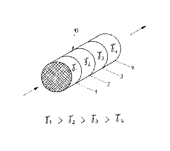
The catalytic converter body is produced in the known
way by compression-molding and subse~uently sintered,
with the shape being selected so that a cylindrical form
is created for the catalytic converter body 10.
To reduce the flow resistance the catalytic converter
body 10 is formed from a plurality of cylinder segments
1-4 arranged one after the other. The individual molded
segments are pressed close to one another and their den-
sity ~ decreases in the direction of through-~low from
1 ~4'
As basic material-metal chips can be used instead of
short metal wire pieces. These are obtained, for example,
by punching, turning, planing or milling in widths of
1-5 mm and lengths of 1-20mm, prePerably of 2~3mm and
5-10mm. Here, the width may also change over the length
according to the form of cutting operation.