Note: Descriptions are shown in the official language in which they were submitted.
1317488 P.332
SELF - PLUGGING BLIND FASTENER
This invention relates to a self-plugging blind
fastenerr and more particularly to a self-plugging blind
fastener of the kind in which, during setting of the
fastener, a plug part of the fastener is locked within
the body of the fastener.
Such blind fasteners are known in a variety of
forms, and generally comprise a tubular body having an
elongate shank and a preformed, radially enlarged, head
at one end of the shank, and an elongated stem which
extends through the bore and part of which projects from
the head end of the body, the fasteners being set by
gripping the projecting part and pulling the stem
relative to the body, so as to deform part of the
fastener and thereby form a blind head remote from the
preformed head, and leave at least a part of the stem
locked within the bore in the body of the set fastener,
where it will act as a plug to close the bore, and may
strengthen the fastener.
Locking the plug part of the stem within the body of
the set fastener prevents it from becoming loose or
separated from the body. Various locking means have been
-
2 1317~88 P.332
employed for this purpose in the past, including the
provision of an annular locking groove in the plug and a
separate deformable collar which is forced to deform and
enter the locking groove, while abutting part of the
body, and thus lock the plug in position relative to the
body. The body may have a recess such as a counterbore at
the head end for receiving the deformed collar.
- It is also usual, although not essential, to remove
the projecting part of the stem from the plug once it has
served its purpose of allowing the fastener to be set,
and, to facilitate this, the stem may be formed with a
breakneck at which the plug and the projecting part will
separate when the stem is subjected to a predetermined
tension.
Such fasteners are set by means of a tool having an
anvil and means for gripping and pulling the projecting
part of the stem relative to the body while the body is
supported, directly or indirectly, at its head end by the
anvil. The tool is also required to cause the locking
means to lock the plug within the body.
In order to be suitable for setting any particular
type of self-plugging blind fastener having locking
means, it is sometimes necessary for the tool to
incorporate elaborate features, particularly in the
design of the anvil, which render the tool vulnerable to
3 13174~8 P.332
damage or malfunction, and are more expensive to produce.
Such elaborate features include the provision of the
anvil with a working face having delicate projeating
parts, or relatively movable parts.
It is therefore desirable that the fastener should
be capable of being set by means of a tool of relatively
simple construction.
In addition, there are a number of other
requirements which it is desirable that a self-plugging
blind fastener should satisfy, and the known fasteners
either have not satisfied all these requirements, or have
done so in ways which are elaborate, expensive, or
otherwise unsatisfacory.
Among these requirements are:-
that the amount of force ~known as the "pushout
force") required to displace the plug from the body of
the set fastener should be very high;
that it should be apparent on visual inspection that
the plug has been satifactorily locked in position;
that the preformed head end of the fastener after
setting should present a substantially flush surface,
free from any protrusion or cavity, and that the forces
required to set the fastener should not be exceptionally
great.
We have now devised a fastener which is believed to
4 1317~88 P.332
offer advantages over known fastellers of similar type.
According to the present invention, there is
provided a self-plugging blind fastener comprising a
tubular body, an elongate stem, and an annular locking
collar,
the tubular body having an elongate shank and a
preformed radially enlarged head at one end of the shank,
the stem being disposed within the bore of the tubular
body and having a plug part having an annular locking
groove, and a tail part which projects from the head end
of the body and whereby the plug part can be pulled, and
moved relative to the body in the direction from the
shank towards the preformed head, to cause the formation
of a blind head remote from the preformed head,
the bore of the body being radially enlarged at the
head end to provide an annular recess which extends
peripherally of the stem and axially into the head from
the head end of the body,
the recess having an outer region having a diameter
substantially greater than that of the bore, and a
tapered inner region in which the diameter of the recess
reduces away from the outer region, to a diameter the
same as that of the bore,
the fastener having means for arresting the movement
of the plug part through the body in the said direction
~317~88
P.332
after formation of a blind head,
the annular locking collar being disposed on the
projecting tail part of the stem, and having a volume
smaller than the combined volumes of the recess and the
locking groove, the locking collar comprising a
deformable locking portion and a radially enlarged
load-bearing head portion, the locking portion having a
volume greater than that of the locking groove and being
deformable radially inwardly, on being forced into the
` 10 inner region of the recess, so as to enter the locking
groove, the head portion having a volume less than that
of the outer region of the recess, and an external
diameter greater than that of the locking portion but
such as to be capable of entering the outer region of the
recess,
the stem having a collar-supporting part between the
locking groove and the projecting part, the collar-
supporting part fitting closely to the walls of the bores
of the body and the collar, and
the angle of taper of the inner region of the recess
being sufficiently great to resist, in cooperation with
the collar-supporting part of the stem, the entry of at
least part of the deformable locking portion into the
inner region of the recess when the locking collar is
subjected to a force sufficient to move the plug in the
6 1317488 P.332
said direction while causing the formation of a blind
head, but sufficiently small to allow the locking portion
to enter more fully into the inner region and to be
deformed thereby when the locking collar is subjected to
an increasing force after movement of the plug relative
to the body has been arrested by the arresting means, the
arresting means being arranged to positively arrest the
movement of the plug in the said direction as soon as
substantially all of the locking groove comes into
register with the annular recess, and thus allow the
application to the locking collar of an increasing force,
whereby the locking collar can be caused to enter more
fully into the recess and be deformed thereby so as to
enter the locking groove.
Embodiments of the invention will now be described,
by way of example, with reference to the accompanying
diagrammatic drawings, in which:-
Figure 1 is an elevational view, partly in section,
of a self-plugging blind fastener according to the
invention, assembled and ready for use;
Figures 2, 3 and 4 are side elevations of parts of
the fastener of Figure 1 in separated relationship,
Figure 2 showing a body partly in section,
Figure 3 showing a locking collar,
and Figure 4 showing a fragment, partly in section,
1317~8~
7 P.332
of a stem;
Figure 5 is a view, partly in section, showing the
fastener of Figure 1 located in apertured workpiece
members to be fastened, together with parts of a tool to
be used for setting the fastener;
Figure 6 is a fragmentary sectional elevation, on an
enlarged scale, showing the fastener in an intermediate
stage of installation, and
Figure 7 is a sectional elevation showing the
fastener in the fully set condition.
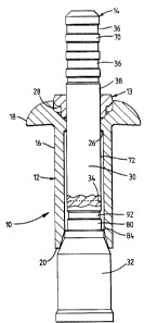
Refering to the drawings, a self-plugging blind
fastener 10 comprises a tubular body 12, an annular
locking collar 13, and an elongate stem 14 which, prior
to use of the fastener and usually during its
manufacture, are assembled together to form a unitary
structure ready for installation in a workpiece, as shown
in Figure 1.
The body 12 is formed of tempered steel of moderate
hardness, and has an elongate shank 16 and a radially
enlarged preformed head 18 formed integrally with the
shank at one end (the "head end") of the body. The other
end of the body is hereinafter referred to as the "blind
end", and is indicated by the reference 20.
A bore 22 extends axially, through the head 18 and
the shank 16, throughout the length of the body 12. The
8 131748~ P.332
bore 22 is radially enlarged within the shank 16 by a
counterbore 24. The counterbore 24 extends from the
blind end 20 towards the head 18, and terminates at a
position which, in this embodiment, is within the shank
and near to the head 18, to provide an annular stop face
26 facing towards the blind end 20.
The counterbore 24 is slightly flared adjacent the
blind end 20, to provide a lead-in.
The bore 22 is also radially enlarged at the head
end, providing an annular recess 28 which extends axially
into the head 18 from the head end of the body, for
receiving the locking collar 13 as will be explained
subsequently.
The fastener 10 of this embodiment is of the
"breakstem" type. The stem 14 is formed of tempered
steel harder than that of the body, and comprises two
principal parts, namely an elongate stem-tail 30, and a
plug 32 which is integrally connected to the stem-tail by
a concealed narrow breakneck 34. The breakneck 34 is
made the weakest part of the stem 14 so that, when the
stem is subjected to a predetermined axial tension, it
will break at the breakneck rather than elsewhere. More
particularly, the fastener 10 is of the type in which the
plug can be pulled into the bore of the body at the blind
end so as to radially expand a part of the shank adjacent
9 1317~88 p.332
to the blind end, and thereby form a blind head remote
from the preformed head 18. In other embodiments of the
invention, however, other arrangements can be adopted for
enabling the formation of a blind head during the setting
of the fastener as will be understood by those skilled in
the art of blind fasteners.
Part of the plug 32 in a region adjacent to the
breakneck 34 is of sufficiently small diameter to be able
to enter a short distance into the counterbored region of
the bore 22 at the tail end of the body, but, in parts
more remote from the breakneck, the diameter of the plug
becomes substantially greater than that of the
counterbore 24, so that it can only enter the bore
further by expanding the shank 16 radially.
The stem-tail is of substantially constant diameter,
and has a smooth surface throughout most of its length,
except that, in order to facilitate gripping and pulling
of the stem, a region of the stem-tail adjacent to the
end remote from the plug is formed with a plurality of
annular pulling grooves 36.
The body 12, collar 13, and stem 14 are assembled
together prior to use so that the plug 32 is adjacent to
the blind end 20 of the body and only partly within the
bore 22, and the stem-tail 30 extends through the bore,
and a part 38 of the stem-tail including the grooved
1317 ~ 8 8 P. 332
region projects from the head end of the body. The
annular locking collar 13 is disposed on the projecting
part 38, which it frictionally engages, and serves to
retain the parts of the fastener in the assembled
condition ready for use.
The bore 22 in the body has a short main region 40,
between the counterbore 24 and the recess 28, in which
the stem-tail 30 forms a light interference fi~t.
The annular recess 28 has an outer region 42, the
diameter of which is substantially greater than that of
both the bore 22 and the stem-tail 30, and a tapered
inner region 44 spaced from the head end of the body by
the outer region 42. The inner region 44 is
substantially frusto-conical, and tapers smoothly in the
direction away from the head end from a maximum diameter
which, in this embodiment, is slightly less than that of
the outer region 42, until it merges with the main region
40 of the bore 22 at a position which is within the head
18.
In this embodiment, the head 18 is of the type known
as "round head", but the body could be formed with a
raised head of a shape other than round, or with a
countersunk head instead of a round head.
Thus, the head 18 has a slightly dished underhead
surface 50 facing towards the blind end and meeting the
1317~88
11 P.332
shank at a position slightly nearer to the blind end than
is the position at which the tapered inner region 44 of
the recess meets the main region 40 of the bore, and a
convexly curved upper surface 52 facing generally away
from the blind end of the body.
; The annular locking collar 13 is formed of a
material which is relatively more easily deformable than
that of the body 12, and in this embodiment is formed of
annealed steel, which is malleable.
The locking collar 13 comprises a head portion 54
and a deformable locking portion 56 integral with the
head portion, and has a cylindrical bore extending
axially through the head portion 54 and locking portion.
The diameter of the bore of the collar is similar to that
of the main region 40 of the bore of the body, and is
such as to enable the collar to fit closely to the
surface of the stem~tail, and desirably, as previously
indicated, to form a friction fit with the stem-tail,
although this is not essential. The locking portion 56
is generally in the form of a hollow cylinder, the
external diameter of which is smaller than the maximum
; diameter of the tapered inner region of the recess, and
is bevelled adjacent its free end. The angle of bevelling
is similar to the taper angle of the inner region of the
recess, and the bevelling presents a bearing surface 58
12 1317~8 P.332
which is able to seat against that peripheral surface of
the body, indicated by the reference 60, which defines
the inner region of the recess.
The head portion 54 of the collar 13 has a maximum
diameter such as to be able to enter and substantially
fill the diameter of the outer region 42 of the recess,
and is sufficiently greater, in diameter and mass, than
the locking portion 56, to be relatively more resistant
to radial deformation than the locking portion. The head
portion 54 presents an annular upper surface 62 remote
from the locking portion, and an annular underhead
surface 64 adjacent to the locking portion. The
peripheral surface of the head portion is angled so as to
provide an upper part 66 which is slightly tapered
towards the upper surface 62, and a relief bevel 68 which
tapers towards the underhead surface 64 at an angle of
about 45 degrees to the axis of the collar.
The shape and dimensions of the locking collar and
the annular recess relative to each other, are not
exactly complementary, but are related to each other in a
way which enables certain functional requirements to be
met, as will be explained subsequently.
The stem of this embodiment is of the type so
adapted that, on being pulled to draw the plug 32 further
into the bore 22, initially, part of the shank adjacent
13 1 31 7~ 8~ P.332
to the tail end of the body will be radially expanded to
form a blind head, and subsequently, the plug may be
drawn further along the bore, until the breakneck is
substantially flush with the upper surface 52 of the
preformed head 18, and, if necessary, or desired, more of
the shank may be expanded within a hole of suitable
diameter in a workpiece in which the fastener is being
installed, so as to fill the hole. In this embodiment,
the plug is adapted to undergo wire-drawing so as to be
capable of elongating under suitably high tensile stress.
Finally, the plug may be locked in position within the
bore of the body so as to plug the bore more or less
permanently and to resist forces which may tend to drive
the plug out of the bore in the direction opposite to
that in which it entered. The stem-tail 30 may be
removed on fracture of the breakneck 34 after the plug
has been locked in position.
Referring again to Figure 1, the stem-tail 30 has a
pulling region 70 adjacent the end remote from the plug
32, in which the several annular pulling grooves 36 are
formed, and a collar-supporting part 72.
The collar-supporting part 72 extends to the
breakneck 34, and is of such a diameter as to form a
close fit in the main region 40 of the bore of the body
and in the bore of the locking collar. In this
14 13 17 ~8 8 P.332
embodiment, the collar~ supporting part is of constant
diameter throughout its length, but it would be possible
for a part of it to be slightly undersize and for it to
increase in diameter near the breakneck so as to
increasingly interfere with the body in the main region
40 of the bore. The collar-supporting part has a smooth
surface which in practice is lubricated so as to be able
to support the collar against radially inward
deformation, and move through the bore of the collar with
little frictional effect, under conditions in which the
collar is being forced strongly into engagement with the
collar-supporting part.
Referring more particularly to Figure 4, the plug
32 has a shaft portion 80 adjacent to the breakneck 34,
and then increases in diameter to present a land 82, and
a stop face 84 between the land and the shaft portion.
The diameter of the plug then increases away from the
breakneck, through a frusto-conical portion 86, to a
diameter substantially greater than that of the
counterbore 24, providing an enlarged cylindrical main
portion 88. The plug terminates, at the end remote from
the breakneck, in a radially enlarged annular rib 90.
An axial cavity (shown only in Figure 7) extends
from the annularly ribbed end of the plug through the
main portion 88 and into the frusto-conical portion 86,
1317~8~ P.332
thereby facilita-tinci wire clrawillg under ten~ile stress of
the portions of the plug which are traversed by the
cavity.
The shaft portion 80 generally has a diameter the
same as that of the collar-supportincJ part 72, but is
formed with an annular locking groove 92 between its
ends.
The locking groove 92 is wide and shallow, and is of
substantially U-shape, having a substantially cylindrical
root 94 between two, spaced, flanks. The flank of the
groove which is nearer the breaknec'~ constitutes a
locking face 96, and the flank remote from the breakneck
constitutes a reaction face 98 which extends
substantially at right angles to the axis of the stem.
The locking face 96 is subscantially frusto-conical,
having an included angle of taper of about lO0 degrees
which is made slightly greater than that of the peripheral
surface 60, in order to avoid the face 96 being either
parallel to the surface 60, or so inclined to the surface
60 that the distance between the locking face 96 and the
surface 60 decreases towards the root 94 of the locking
groove 92.
The axial length of the shaft portion 80 is
substantially the same as (but not greater than) the
distance between the stop face 26 in the bore 22 and the
head end of the body. The locking groove 92 is spaced
from the stop face 84 by a distance substantially equal
to (but not greater than) the distance between the stop
16 1317~88 P.332
face 26 and the axially inner end of the recess 28.
The stop faces 26 and 84 together constitute means
~or arresting the movement of the plug through the bore
of the body. Thus, when the stem is pulled to draw the
5 plug in the direction from the tail end of the shank
towards the preformed head, a blind head is formed, and
subsequently the stop faces 26 and 84 come into abutment
and arrest further movement of the plug relative to the
body.
The dimensions and disposition of the various parts
are such that, when the two stop faces abut each other,
the breakneck 34 will be aligned with, or slightly below,
the upper surface 52 at the head end of the body, and the
locking groove 92 will be in register with the inner
region 44 of the recess 28, with the reaction face 98
substantially aligned with (but not nearer to the head
end than) the point at which the tapered inner region 44
merges with the main region 40 of the bore of the body.
As previously mentioned, the breakneck 34 is
concealed. Thus, the breakneck lies at the root of a
peripheral groove which is overhung by lips formed on the
adjacent collar-supporting part 72 of the stem-tail, and
the shaft portion 80 of the plug respectively, the lip on
the collar-supporting part 72 overlapping that on the
shaft portion so as to enclose the groove, thereby
17 1317~88 P.332
concealing the breakneck, and serving to prevent ingress
of materials into the groove.
Further details of the construction of the fastener
10 will become apparent from the following description,
by way of example, of the manner in which the fastener
may be used to fasten members together.
Referring now to Figure 5, apertured workpiece
members 100, 102 to be fastened are brought together with
their apertures in register, and the assembled fastener 10
is inserted into the registering apertures so that the
underhead surface 50 of the preformed head 18 abuts the
near face of the member 100, and the shank of the body
extends through both members and projects beyond the
opposite, or "blind" face of the member 102.
The fastener is then set by means of a suitable
setting tool represented in the drawings by only an
annular anvil 104, and a pair gripping and pulling jaws
106 which are reciprocable relative to the anvil.
The anvil 104 has an annular flat face 108 with a
central aperture through which the projecting part 38 of
the stem of the fastener can be passed into engagement
with the jaws 106. The diameter of the face of the anvil
is greater than that of the upper surface 62 of the
locking collar, but need not be as great as the diameter
of the preformed head 18 of the body.
18 1317~88 P.332
The diameter of the central aperture of the anvil is
sufficiently great to allow passage of the stem-tail, but
preferably is not greater than the diameter of the bore
of the locking collar.
Either before, or after insertion of the fastener
into the apertures of the workpiece members, the
projecting part 38 of the stem-tail 30 is inserted
through the central aperture of the anvil and into
engagement with the jaws 106. The tool is then actuated
to grip and pull the stem-tail further into the tool
through the anvil, thereby causing the face 108 of the
anvil to apply a reaction force to the upper surface 62
of the head portion of the collar. This reaction force
is in turn transmitted to the body 12 of the fastener
through the bearing surface 58 of the collar which is
forced into engagement with the surface 60 peripherally
of the tapered inner region 44 of the recess 28. Thus
the anvil supports the body 12.
In this embodiment, the included angle of taper of
the inner region 44 of the recess is 90 degrees, giving a
suitable compromise between transmitting all of the
axially applied reaction force to the body, and
translating the axial force into a radially inwardly
directed force whereby the deformable part of the collar
can be deformed radially inwardly. However, the required
19 1317~88 P.332
taper angle will depend on a number of factors, in
particular the hardness of the material of the collar,
and can be determined empirically.
As the body is supported by the anvil, the plug 32
is drawn further into the counterbore, progressively
; expanding the shank radially to form a blind head 110
which engages the blind member 102 of the workpiece and,
in cooperation with the preformed head, fastens the two
members 100, 102 together.
Initially during this movement, the force applied to
the collar 13 drives the collar further into the recess,
causing some deformation of the deformable locking
portion 56 which then becomes supported by both the
collar-supporting part 72 of the stem-tail and the
peripheral surface 60 of the body. Eventually however,
a balance is established between the tendency for the
collar to deform further, and the tendency for the plug
to undergo wiredrawing and become elongated. As the head
portion 54 of the collar is of greater diameter and mass
than the locking portion 56, the head portion 54 is not
appreciably deformed at this stage.
Continued pulling of the stem draws the shaft
portion 80 of the plug nearer to the head end of the
body, so that the locking groove begins to come into
register with the tapered inner region of the recess ~ust
1317~88 P-332
before the stop faces 26 and 84 abut each other. The
deformable portion of the collar then lacks the support
of the collar-supporting part of the stem and the shaft
portion 80 of the plug, and then begins again to be
deformed, and enters the locking groove as shown in
Figure 6. However, the plug continues either to move, or
to elongate, until the stop faces eventually abut each
~-other, at which stage the locking groove is fully in
register with the recess, and the reaction face 38 is at,
-10 or nearly at, the junction of the recess 28 and the main
region 40 of the bore.
As soon as the stop faces abut each other, the force
required to move, or wire-draw, the plug increases
substantially, and consequently the increased reaction
force between the peripheral surface 60 and the
deformable portion causes the deformable portion to enter
more fully into the locking groove.
The reaction face 98 lies at an angle, relative to
the peripheral surface 60, which is appreciably greater
than 90 degrees, and this ensures that when material of
the collar moves parallel to the surface 60 and then
meets the reaction face, it is then deflected radially
inwardly towards the root of the locking groove.
In particular, it is believed that the leading end
of the deformable portion comes into abutment with the
21 1317 ~ ~ 8 P . 332
reaction face 98 of the locking groove, and material
behind the leading end of the deformable portion becomes
plastic, the plastic material then flowing into the
groove 92 and back-filling it in the direction from the
reaction face towards the locking face 96, so that
eventually material of the deformable portion becomes
packed between the locking face 96 of the groove and the
- peripheral surface 60 of the body, and is therefore able
to oppose regressive movement of the plug within the
body.
During this deformation, the head portion 54 of the
collar is able to enter further into the outer region 42
of the recess under the urging of the face 108 of the
anvil, until eventually the face 108 brings the upper
surface 62 into register with the upper surface 52 of the
preformed head, and itself engages the upper surface of
the preformed head.
At this stage, with the anvil face 104 abutting the
preformed head, the force required to produce further
relative movement between the anvil face 108 and the
stem-tail again increases. With the tool applying
increasing force, this results in fracture of the
breakneck, allowing the stem-tail to be discarded, and
leaving the fastener set, with the plug locked in the
body.
22 1317~8~ P.332
It will be appreciated that, while initially the
deformation of the collar is by extrusion between the
peripheral surface of the body, and the collar-supporting
part of the stem, the final deformation occurs as a
result of the collar being crushed between the anvil and
the reaction face 98 of the stem.
In order to ensure that the upper surfaces 52 and 62
can always be brought into register, and thus avoid
unevenness at the head of the set fastener despite
dimensional variations within manufacturing tolerances,
the shape and dimensions of the collar and the recess are
so related that, when the collar is entered into the
recess so that its upper surface 62 registers with the
upper surface 52, and the locking groove has been
substantially filled by material of the deformable
locking portion 56, there remains a void 120 between the
underhead surface 64 of the head portion of the collar
and the surface 60 peripherally of the recess, as can be
seen in Figure 7. Thus, the void is available to
accommodate additional material of the collar should the
need arise as a result of, for example variation in
dimensions, within predetermined tolerances, of the
various parts and features of the fastener.
More particularly, the shape and dimensions of the
locking collar, and in particular those of the locking
23 1317~88 P.332
portion, are made such that, on applying a force to the
upper surface of the collar so as to force the collar
more fully into the recess, the deformable portion will
continue to enter the inner region of the recess, and be
deformed thereby so as to substantially fill the locking
groove before the upper surface of the collar becomes
flush with the upper surface of the preformed head.
- Although the invention has been described in the
context of locking means applied to a selfplugging blind
fastener of the kind in which a blind head can be formed
by pulling a radially enlarged part of the plug into the
bore, and thereby radially expanding the shank, the
invention can also be applied to self-plugging blind
fasteners in which other means for forming a blind head
are provided. Thus, for example, a blind head can be
formed by causing axial collapse of the shank to produce
an annular fold of laryer diameter than that of the shank
before folding. Such alternatives are well known in the
art of blind fastening, and appropriate constructions,
and modifications of the preferred structures described
hereln, will be readily apparent to those skilled in the
art.