Note: Descriptions are shown in the official language in which they were submitted.
F-1435 1 3 1 7 6 1 6 PATENT
~UICK DISCONNECT DEVICE
Field of the Invention
This invention relates to a coupling device
and more particularly concerns an apparatus and method
of utilization thereof of a quick disconnect device for
coupling a work tool (or end of arm tooling device -
EOAT) to a machine (support or robot) and providing a
quick disconnect for electrical and fluid connections.
Disclosure Statement
This application is an improvement to the
quick disconnect device disclosed in U.S. Patent
4,733,053. It is known in the art to provide quick
disconnect devices for coupling a work tool to a
machine wherein the coupling (or locking mechanism is
independent of the portions of the coupling which
lS provide alignment. It is a desire of the present
invention to provide a quick disconnect coupling as
described in the above-noted application which provides
a more simplified construction and also protects the
coupling mechanism from the environment.
Protection of the coupling mechanism from the
environment is helpful since the coupling mechanism can
sometimes be contaminated wLth particles from the
environment such as dirt or metal shavings. Also it is
desirable to protect the coupling mechanism from
2s possible exposure to chemicals which over a passage of
t1me can sometimes accumulate wlthin the coupling
~ ~mechanism or possibly have a corrosive effect. Another
`~ ~ desire of the present invention is to provide a quick
disconnect coupling which can not couple together
~::,,.,.. ,,,,,.,, : .
.
.
2 1317616
unless the coupling halves are properly mated and
aligned. Therefore, some means must be provided to
prevent the coupling from being falsely activated to
lock the coupling halves together when the coupling
halves are not mated and properly aligned.
Summary of the Invention
To meet the above-noted and other desires the
present invention is brought forth. The present
invention is a work-tool to work-station coupling
device wherein alignment is independent of the coupling
mechanism. The coupling mechanism has a closure which
protects the coupling mechanism from the environment
when the coupling halves are separated. The closure
also functions to prevent operation of the coupling
mechanism when the coupling halves are not aligned or
mated.
It is an object of the present invention to
provide an apparatus and method of utilization thereof
of a quick disconnect coupling for a work station and a
work tool.
It is also an object of the present invention
to provide a quick disconnect coupling for connecting a
tool to machine, including a tool adapter for holding
the tool having a generally axial central cavity, and
at least one generally axially orientated member
bordering the central cavity and projecting towards the
machine, and a tGol changer adapted for sequentially
mating and coupling with the tool adapter and connected
with the machine, the tool changer including a shell
with a generally axial interior chamber, a first
passage fluidly connecting the outside of the shell and
the interior chamber, and the interior chamber shell
:
3 1317616
having at least one generally radial aperture
intersecting the chamber axially separated from the
first passage and towards the tool adapter, a piston
slidably mounted in the interior chamber and responsive
to a fluid fed into the interior chamber from the first
passage, the piston having a rod portion with a cam
portion adjacent the radial aperture, a locking member
movably mounted within the radial aperture for
interacting with the cam portion of the rod and the
axially orientated member to couple the tool changer
with the tool adapter, and closure means biased to a
first position whereby the radial aperture is closed
when the tool changer and the tool adapter are not
mated and whereby the closure means is moved ko a
second position by the axially orientated member to
open the radial aperture when the tool changer and the
tool adapter are mated, the opening of the aperture
allowing the piston to move to a position to cause the
].ocking member to be captured between the cam portion
: 20 of the rod and the axially orientated member to couple
the tool changer with the tool adapter.
It is also an object o the present invention
to provide a quick disconnect for coupling an EOAT to a
robot, the coupling including a tool adapter connected
with the EOAT having a generally axial central cavity,
and a generally tubular axially orientated member
bordering the central cavity projecting towards the
robot having an interior flange at its end toward the
robot and the tool adapter having a frusto conical
surface on its end toward the robot, and a tool changer
adapted for sequentially mating and coupling with the
tool adapter along a frusto conical surface
: : 3
':~
~ ., .
4 1317616
complementary to the tool adapter frusto conical
surface and for connection with the robot, the tool
changer including a cylindrical shell with a generally
axial cylindrical interior chamber with an axial center
line, a first and second passage connecting the outside
of the shell and the interior chamber and the interior
chamber having a plurality of generally radial
apertures intersecting the chamber axially separated
from the first passage and towards the tool adapter, a
piston slidably mounted in the interior chamber
dividing the interior chamber between the first and
second passages and responsive to a fluid fed into the
interior chamber from the first or second passages, the
piston having an attached rod with a cammed portion
. 15 having a 7 cam angle with a line parallel with the
axial center line of the interior chamber and the cam
portion being adjacent to the radial apertures, a
locking ball movably mounted within each of the radial
apertures for interacting with the cam portion of the
rod and the flange of the axially orientated cylinder
to couple the tool changer with the tool adapter, and
closure means including a fixed annular cover
surrounding the interior chamber and a spring biased
ring biased to a first position whereby the radial
apertures are closed when the tool changer and the tool
: adapter are not mated and the spring biased ring being
moved to a second position whereby the radial apertures
are open by the axially orientated member when the tool
changer and the tool adapter are mated, the opening of
the aperture allowing the locking balls to be captured
between the cam portion of the rod and the interior
:; :
,
1 31 761 6
flange of the axially orientated member to couple the
tool changer with the tool adapter.
It is yet still another object of the present
invention to provide a method of sequentially mating
and coupling an EOAT connected with a tool adapter
having a generally axial central cavity and at least
one generally axially orientated member bordering the
central cavity and projecting away ~rom the EOAT, to a
robot having a connected tool changer which includes a
shell with a generally axial interior chamber including
a first passase fluidly connectlng the outside of the
shell with the interior chamber, at least one generally
radial aperture intersecting the interior chamber
axially separated from the first passage and towards
:. 15 the tool adapter, a piston slidably mounted in the
interior chamber and responsive to a fluid fed into the
interior chamber from the first passage, the piston
having an attached rod with a cam portion adjacent the
radial aperture, a locking member movably mounted
within the radial aperture for interacting with the cam
portion of the rod and the axially orientated member to
couple the tool adapter with the tool connector,
closure means biased to a first position whereby the
radial aperture is closed when the tool changer and the
tool adapter are not mated and whereby the closure
means is moved by the axially oriented member to a
second position opening the radial aperture when the
tool changer and the tool adapter are mated the openin~
of the aperture allowing the piston to move to a
position causing the locking member to be captured
between the cam portion of the rod and the axially
orlentated ~ember to couple the tool changer with the
~ ~ .
~:`
- "~
6 1317616
tool adapter, the method including mating the tool
adapter with the tool changer and aligning the tool
adapter with the tool changer, contacting the axially
orientated member of the tool adapter with the closure
means of the tool changer to open the radial aperture,
fluidly communicating the interior passage with the
outside of the shell of the tool changer to move the
piston, interacting the cam portion of the piston with
the locking member whereby the locking member is forced
outward contacting the axially orientated member of the
tool adapter to couple the tool adapter with the tool
changer~
Other objects, desires and advantages of the
present invention will become more apparent to those
skilled in the art as the nature of the invention is
better understood from the accompanying drawings and a
detailed description.
Brief Description of the Drawings
Figure 1 is a sectional view with portions in
front elevation of a preferred embodiment coupling of
the present invention with the tool adapter coupling
halve (connected with an EOAT) separated from a tool
changer coupling halve (connected with a robot);
Figures 2 and 3 are views taken along lines
2-2 and 3-3 of Figure 1, respectively; and
Figure 4 is a sectional view with portions in
front elevation illustrating the tool adapter and the
tool changer halves of the coupling mated and coupled
together;
Figure 5 is a view taXen along line 5-5 of
Figure 4; and
,
,
`` 1317616
Figure 6 is a sectional view of an alternative
preferred embodiment of the present invention.
Detailed Description of the Drawings
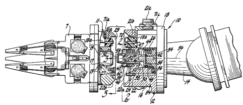
Referring to Figure 1 an EOAT 7 has connected
thereto the female portion of the quick disconnect
coupling 10 of the present invention commonly referred
to as ~he tool adapter 11. Connected with the robot 14
is the male portion of the coupling commonly referred
to as the tool changer 12. The tool changer is adapted
for sequentially mating and coupling with the tool
adapter 11. Referring additionally to Figures 2, 3, 4
and 5, the tool adapter 11 is connected with the EOAT 7
and provides fluid and electrical connections for the
EOAT 7. The end of the tool adapter 11 towards the
robot 14 (opposite the EOAT 7) has a cylindrical axial
central cavity 13. The tool adapter 11 also has at
least one generally axially orientated member 15
bordering the central cavity 13. As shown in Figures 1
and 2, axially oriented member 15 is tubular shaped
having an inward facing flange 17. The tool adapter 11
also has an electrical cable or lines 19a and connector
21a. The electrical connector 21b illustrated provides
thirteen lines l9b (commonly referred to as leads) with
spring loaded contacts 70. Connectors 21a, b and c are
also made to be removable by removal of fasteners 71a !
b and c or substitution of an electrical connector
with a different amount of lines.
For fluidic coupling of air or hydraulic
feeds, fluid lines 23 are provided. Fluid lines 23
intersect surface 25 of the tool adapter 11. Hardened
plate 24 has apertures 37 with inserted O-rings 90
, . . .
, , .
8 1317616
(Figure 23 to mate and seal fluid line 23 as it extends
into the tool changer 12.
The tool changer 12 has a cylindrical shell 94
which includes a cylinder 16 and a back plate 18. The
tool changer 12 has a frusto conical surface 20a that
is complementary to the frusto conical surface 20b on
the tool adapter 11. The tool changer 12 also is
provided for rough alignment an axial locating pin 22.
Locator plate 27 tFigure 3) fixably connected with tool
adapter 11 is provided to encircle locating pin 22. The
tool changer 12 has a generally axial interior chamber
26 formed by cylinder 16 and inner shell member 30, cap
32 and plug 34.
Intersec~ing the interior chamber are first 36
and second 38 fluid passages usually provided for a
pneumatic air control system. The interior chamber 26
also has axially separated from the first 36 and second
38 passages, on an end of the tool changer away from
the robot 14 (towards the tool adapter 11) a plurality
of generally radial apertures 40 usually equally
geometrically spaced. Slidably mounted within the
interior chamber is a piston 42. The piston 42 has
~` ixably attached thereto a rod 44 with a cam portion
46. If desired, the piston 42 can be spring biased by
a spring 96 captured between plug 34 and the piston 42.
The piston 42 also has an O-ring 48 within an annular
groove 47 of the piston which divides the interior
chamber 26 into separate sealed sections. The piston
rod 44 also has a second annular chamber with an O-ring
50 which ~luidly isolates the apertures 40 from the
remainder of the interior chamber 26. Movably mounted
within each radial aperture 40 is a locking member
~'-
,
,`~ 8
.
.:
.,
.
9 ! 1 3 1 7 6 1 6
typically a ball 52 to couple the tool changer 12 with
the tool adapter 11. The piston has an actuated
(Figure 1) and a nonactuated (Figure 2) position. In
the nonactuated position, the piston 42 is in a
generally retracted position and the balls 52 are
allowed to move inwardly. In the extended coupling
position, the cam portion 46 of the piston rod 44
interacts with the balls 52 at a cam angle between 5
and 9 and illustrated in Figure 2 at a 7 angle from a
line parallel to the axial center line 54 of the
interior chamber 26. The interaction of the cam
portion 46 of the piston rod 44 with the balls 52
causes the balls 52 to be captured between the cam
portion 46 and the flange 12 of the axially elongated
; 15 member 15 coupling the tool chamber 12 with the tool
adapter 11.
When the tool changer 12 and the tool adapter
11 are uncoupled, the apertures 40 are covered by a
closure means 56 L-shaped ring 58 which is spring
biased. The L-shaped ring 58 in the uncoupled position
mates with a fixed angular cover 60, which surrounds
~ the interior chamber 26 to seal apertures 40 from the
; environment.
It has usually been found that after coupling
of the tool changer 12 with the tool adapter 11 the 7
cam angle allows the coupling halves to be held
together even when air pressure is not available from
the passage 36. The force exerted by spring 96 further
ensures that the coupling halves are held together. A
7 cam angle will cause the uncoupling force to be
approximately eight (8) times greater ~han the force
` exerted on piston 42 by the differential fluid pressure
':
~`
. ' .
10 1317616
of the first 36 and second 38 passages (compensated by
the differential areas of piston 42 by virtue of rod
44) and by the force exerted by the spring 96.
To couple the tool adapter with the tool
changer 12 the axially elongated member 15 first pushes
the closure L-shaped ring 58 downward. The above
action opens apertures 40, allowing the balls 52 to be
pushed outward by the cam portion 46 of the piston rod
44. Therefore, whenever there is not proper alignment
between the coupling halves, the axially elongated
member 15 can not push down the L-shaped ring 58 and
the piston rod 44 will not be allowed to move to an
activated position allowing the coupling halves to
couple together. The above described feature prevents
false coupling of the parts when alignment is not
proper even when air pressure is present in first
passage 36 since closures 40 are closed by L-shaped
ring 58, preventing the outward movement of balls 52.
To uncouple the coupling halves, pressurized air is
connected with second passage 38, thereby retracting
piston rod 44 against spring 96 and allowing balls 52
to move radially inward, thereby releasing axially
elongated member 15. The tool adapter 11 is now
released and can be removed.
Figure 6 is an alternate embodiment coupling
110 with parts similar to those illustrated in Figures
1-4 having the same referenced numerals prefi~ed by a
1. Line 123 is sealed by a concentric O-ring 190
captured in a tapered aperture 37 of hardened plate
124. Abushing 250 concentric with the O-ring 190 and
~,
; 10
' .
. .
, ,
1 31 761 6
connected with tool adapter 111 is provided for mating
and sealing with the O-ring 190.
The bushing 250 has a diameter smaller than
the minor diameter 237 of aperture 137. One advantage
offered by this design is that there is a gap 227
between surface 125 and the top surface 224 of plate
124. The gap allows room for dirt or other particles
and prevents the particles from interfering with the
sealing of line 23 or interfering with the mating of
tool adapter 111 with tool changer 112.
If surface 125 was used to mate and seal with
O-ring 190 the compression of O-ring 190 would be
; limited to the cross sectional diameter of O-ring 190
minus the thickness of pla~e 124. ~owever, bushing 250
with a diameter less than the minor diameter 237 of
aperture 137 can now further compress O-ring 190 below
the level of the top surface 224 of plate 124. The
above configuration allows busing 250 to further
compress O-ring 190 to a thickness less than that of
plate 124 providing better sealing.
Since surface 125 no longer has to be flush
with surface 224 (to compress O-ring 190) the frusto
conical surfaces 120a and 120b can now be formed near
at a 6 instead of a 45 angle (with axial center line
154). The 45 angle was provided to assure the flush
contact between surface 125 and plate 124 when the
diameter of the tool adapter conical surface 120b was
towards the upper end of its dimensional tolerance. If
the tool adapter 111 is mated with the tool changer
112, the tool adapter 111 cannot be separated from the
tool changer 112 without relative axial movement
between the tool adapter 111 and the tool changer 112
~ : -
~ ~ .
11
,
.
1317616
12
or deformation of one of the frusto conical surfaces
121a or 120b. To illustrate the above a diametrically
bisecting line 204 is drawn between a point of
outermost contact 208 of frusto conical surfaces 120a
and 120b and a point of innermost contact 206 of frusto
conical surfaces 120a and 120b. Moment force 205
influences tool adapter 1110 Point 206 on surface
frusto conical surface 120b will have to take the path
of arc 205 if the tool adapter 111 and tool changer
remain fixed at point 208. Therefore deformation of
tool changer 112 frusto conical surface 120a must
occur. Since separation cannot occur under the
influence of moment forces without deformation, the
coupling 110 i5 more prone to fail under an axial load.
The above failure mode is desirable because of the
previously explained approximately 8:1 axial force
advantage of the coupling.
It is an object of the present invention to
`j provide a method of sequentially mating and coupling a
tool 7 connected with a tool adapter 11 having a
~ generally axial central cavity 13 and at least one
;` generally axially orientated member 15 bordering the
central cavity 13 and projecting away from the tool 11,
to a machine 14 having a connected tool changer 12
which includes a shell 94 with a generally axial
interior chamber 26 including a first passage 36
fluidly connecting the outside of the shell 94 with the
interior chamber 26, at least one generally radial
aperture 40 intersecting the interior chamber axially
separated from the first passage 3Ç and towards the
tool adapter 11, a piston 42 slidably mounted in the
interlor chamber and responsive to a fluid fed into the
12
13 1 31 761 6
interior chamber from the first passage 36, the piston
having an attached rod 44 with a cam portion 46
adjacent the radial aperture 40, a locking member 52
movably mounted within the radial aperture 40 for
interacting with the cam portion 46 of the rod 44 and
the axially orientated member 15 to couple the tool
adapter 11 with the tool connector 12, closure means 56
biased to a first position whereby the radial aperture
40 is closed when the tool changer 12 and the tool
adapter 11 are not mated and whereby the closure means
56 is moved by the axially oriented member 15 to a
second position opening the radial aperture 40 when the
tool changer 12 and the tool adapter 11 are mated the
opening of the aperture 40 allowing the piston 44 to
move to a position causing the locking member 52 to be
captured between the cam portion 46 of the rod 44 and
the axially orientated member 15 to couple the tool
changer 12 with the tool adapter 11, the method
including the ~ollowing steps:
1. Mating the tool adapter 11 with the tool
changer 12 and aligning the tool adapter 11 with the
tool changer 12;
; 2. Contacting the axially orientated member
: 15 of the tool adapter 11 with the closure means 56 of
:~ 25 the tool changer 12 to open the radial aperture 40;
3. Fluidly communicating the interior passage
36 with the outside of the shell 94 of the tool changer
12 to move the piston 42;
4. Interacting the cam portion 46 of the
piston with the locking member 52 whereby the locking
member 52 is forced outward contacting the axially
13
, : ~
-
1 31 76 1 6
14
orientated member 15 of the tool adapter 11 to couple
the tool adapter with the tool changer 12.
While an embodiment of the present invention
has been explained it will be readily apparent to those
skilled in the art of the various modifications which
can be made to the present invention without departing
from the spirit and scope of this application as it is
encompassed by the following claims.
,~
~; 14
~ - - -- .
,.