Note: Descriptions are shown in the official language in which they were submitted.
~ 1535
1317644
LARGE AREA ~ICROWAVE PLASMA APPARATUS
FIELD OF THE INVENTION
The instant invention relates generally to a
novel microwave apparatus for effecting a uniform
microwave initiated glow discharge plasma over a large
area within the near field distance of the
application. The microwave apparatus apparatus
~;~ includes a vacuum vessel for sustaining a plasma, a
source of process gas, and a microwave applicator
adapted to either radiate or transmit via evanescent
waves into the interior of said vacuum vessel. The
microwave energy apparatus further includes an
isolating window for separating the microwave
applicator from the plasma region developed in the
vacuum vessel.
;,; :
BACKGROUND OF THE INVENTION
Conventional microwave ovens are designed to
be uniformly heat food products through the use of
mechanical means that average out microwave energy
non-uniformities while taking advantage of the
relatively long thermal relaxation times of the food
products which are being he~ated. The same techniques
cannot be used for uniformly exciting gases to create
a~plasma. This~is;because of~t~he short relaxation
times of the gases. The~fan~s and cther mechanical
mlcrowave dispersers" us~e;d ln~oven technology, are
30~ unable, regardless of~how~fa;st they can rotate, to
assure a uniform dispers~lon~of microwave~energy, on a
time scale appropriat~e for pl~dsma excitation~ To
accomplish the uniform microwave excitation of a
plasma, other~means~must be employed. Prior examples
of microwave plasma deposition techniques are
,
,, ,
'. : , . . , :.
'` ' ` ' . ~ '
~ ~ .
v~ 1535
1~176~
-2-
illustrative of the s-tate oF the art and highlight
both the problems encountered in increasing the
uniformity o-f eneryy distribution from the applicator
and the advantages provided by the novel microwave
plasma generating structure of the instant invention.
Commonly assigned, U.S. Patent Nos. 4,517,223
and 4,504,518 to Ovshinsky, et al, both entitled
"METHOD OF MAI<ING AMORPHOUS SEMICONDUCTOR ALLOYS AND
DEVICES USING MICROWAVE ENERGY", describe
processes for the deposition of thin films onto small
area substrates in a low pressure, microwave glow
discharge plasma. As specifically noted in these
Ovshinsky, et al patents, operation in the disclosed
low pressure regimes not only eliminates powder and
polymeric formations in the plasma, but also provides
the most economic mode of plasma deposition. While
these patents describe a truly remarkable regime of
low pressure and high energy density, deposition
utilizing microwave energy, i.e., at substantially the
rninimum of the Paschen curve, th~e problem of
uniformity of deposition over large areas remains
unaddressed.
` Turning now to microwaVe applicators for
;~ large area substrates, commonly assigned U.S. Patent
No. 4,729,341 of Fourni r _ ~al, for "METHOD AND
APP~RATUS EOR MAKING ELECTROPHOTOGR-APHIC DEVICES",
describes a low pressure microwave initiated plasma
process for depositing a photoconductive semiconductor
th~in film on a large~area cylindrical substrate using
~ a pair~ o-f~radiative waveguide applicators in a high
p~ower process. However, the principles of large area
deposition descri;bed therein are limited to
cylindrically sh~aped substrates, such as
electrophotographic photoreceptors~, and the teachings
. ,.:
: '
- 1535
1317~
provided therein are not directly transferable to
large area, generally planar substrates.
Many workers in the field have disclosed
methods of processing thin films utilizing high power
of microwave sustained plasmas. However, microwave
plasmas have not been altogether appropriate for large
surface area and/or low pressure deposition. This is
because of the non-uniformity of the resulting surface
treatment, a consequence of the non-uniformity of the
energy. One attempt to provide greater uniformly was
lo the use of a slow wave microwave structure. A problem
that is inherent in slow wave structures, however is
; the very rapid decline of microwave coupling into the
plasma as a function of distance transverse to the
microwave applicator. This problem has been addressed
in the prior art by various structures that vary the
spacing of the slow wave structure from the substrate
to be processed. In this way the energy density at
the surface of the substrate is constant along the
direction of movement of the substrate. For example,
U.S. Patent No. 3,814,983 to Weissfloch, et al for
"APPARATUS AND METHOD FOR PLASMA GENERATION AND
MATERIAL TREATMENT WITH ELECTROMAGNETIC RADIATION and
U.S. Patent No. 4,521,717 to Kieser, et al,~for
"APPARATUS FOR PRODUCING A MICROWAVE PLASMA FOR THE
TREATMENT OF SUBSTRATE IN PARTICULAR FOR THE PLASMA
POLYMERIZATION OF MONITORS T~HEREON", both address this
prob;lem by proposing various~spat~ial relationships
between the microwave applicator and the substrate to
be processed.
~ More,~particularly, Weissfloch, et al
discloses that in order to obtain the uniform electric
field intensity necessary~for a plasma of uniform
power density along;the~full~length of the slow wave
waveguide structure~, it is necessary to incline the
waveguide structure at an angle with respect to the
`: :
: , .
,. . . .
, ' ' .
.
` 1535
- ~317~4~
--4--
-
substrate. It should be apparent, however,
inclination of the slow wave waveguide structure to
achieve uniformity with réspect to the substrate leads
to an inefficient coupling of microwave energy into
the plasma.
Recognizing this defic;ency, Kieser, et al
described that the conditions resulting from
superposing of two energy inputs, i.e., two microwave
applicators~ can be further improved if the two slow
wave applicators are set at an angle to each other
o such that the planes normal to the medians of the
applicators intersect at a straight line which extends
parallel to the surfaces of the substrate to be
treated and at right angles to the direction of travel
of the substrate. Moreover, Kieser, et al recommended
that in order to avoid destructive interference of the
wave field patterns of the two applicators, the
applicators should be displaced from each other
transversely of the direction of travel of the
~; substrate by a distance equal to half of the space
between the cross-bars of the waveguide. In this way
; the microwave field pattern is substantially
suppressed.
The problem of plasma uniformity and more
; ~ particularly, energy uniformity was treated by J.
Asmussen and his co-~workers, for example in T. Roppel,
et al "LOW TEMPERATURE OXIDATION~OF SILICON USING A
MICROWAVE PLAS~MA DISC~SOURCE", J. Vac. Sci. Tech. B-4
(January-February 1986) pp. 295-298 and M. Dahimene
and J. Asmussen "THE PERFORMANCE OF MIC~ROWAVE ION
30 ~ SOURCE IMMERSED IN A MULTICUSP STATIC MAGNETIC FIELD"
J. Vac. Sci. Tech.~8;-4~(January-February 1986) pp.
126-130. In these, as~well as other papers, Asmussen
and his co-workers described a microwave reactor which
they refer to as a microwave plasma disc source
"MPDS"). The plasma is reported to be in the shape
., ~ :
:;:: ~ :: :
~: ' , .
.
:` .
1535
1317644
of a disc or tablet, with a diameter that is a
function of microwave frequency. A critical advantage
claimed by Asmussen and his co-workers is that the
plasma disc source is scalable with frequency: that
is, at the normal microwave frequency of 2.45
gigahertz, the plasma disc diameter is 10 centimeters
and the plasma disc thickness is 1.5 centimeters; but
that the disc diameter can be increased by reducing
the microwave frequency. In this way, the plasma
geometry was said to to be scalable to large
lo diameters, potentially yielding a uniform plasma
density over a large surface area. However, Asmussen
only described a microwave plasma disc source which is
operation at 2.45 gigahertz~ where the plasma confined
diameter is 10 centimeters and the plasma volume is
118 cubic centimeters. This remains far from a large
surface area. In order to provide for deposition onto
large area substrates, Asmussen proposed a system
operational at the lower frequency of 915 megahertz,
which would provide a plasma diameter of approximately
~: 20 40 centimeters with a plasma volume of 2000 cubic
centimeters.
Asmussen further described that the microwave
plasma disc source can be used as a broad beam ion
~; source or as a plasma source for material processing
and can be scaled up to discharge diameters in excess
of 1 meter by operating at still lower frequenciesg
for exa~ple 400 megahertz. Such a microwave plasma
disc source while, in principle, providing for
deposition onto relatively large surface areas,
requires an adjustment~ to lower frequency. There are
severe economic consequences of this approach to
..
variation of the dimensions of a plasma processing
machine. Only 2.45 GHz magnetrons have been developed
to be both inexpensi-ve and to have large power
~ capabilities. High power microwave sources at other
;`~
.
~ ,
1535
131764~
--6--
-
fixed frequencies remain expensive and variable
frequency high power microwave sources are extremely
expens~ve.
Furthermore, the deposited material quality
and deposition rate is dependent on excitation
frequency. Further, the modulation of frequency to
increase plasma dimensions compromises material
quality and film deposition rate. Additionally, the
magnets which are used in the system disclosed by
Asmussen must be larger in size, and different in
o field strength as the excitation frequency is
changed. Thus, as a means of changing the plasma
dimensions, Asmussen's approach has the disadvantage
of rigidly coupling other important deposition
parameters and therefore reducing operational
flexibility.
Workers at Hitachi have described, for
example in U.S. Patent No. 4,481,229 to Suzuki, et
al,the use of electron cyclotron resonance (ECR) to
obtain a high power plasma having a relatively high
degree of uniformity over a limited surface area.
However, the Hitachi patent does not teach, nor even
suggest a method by which uniform large area plasmas
may be achieved. Moreover, the use of ECR imposes the
~" ~ added requirement of highly uniform magnetic field
structures in the microwave apparatus, and may be
restricted in operation to only those very low
pressure regimes where~electron collision times are
long enough to allow the ECR cond~ition~to be
~ achieved. ~
t~ 30~ U.S. Patent Nos~. 4,517,223 and 4,729,341
referred to above, descr~ibe the~necessity of using
very low pressures in very high microwave power
density plasmas. ~The use of low pressures in
necessary in order to obtain high deposition rates
and/or high gas utilization; U~S. Patents 4,517,223
,
' ` '
` 1535 1317~4~
and 4,729,341 empnasize the criticality of low plasma
pressure in order to economically carry out the plasma
processes. However, the relationship between high
deposition rates, high gas utilization, high power
density, and low pressure further limits the utility
of slow wave structures and electron-cyclotron
resonance methods. The limitations of the slow wave
structure and of the electron-cyclotron resonance
methods are obviated and the deposition rates and low
pressure regimes described in the aforementioned U.S.
Patent Nos. 4,517,223 and 4,729,341 are obtained by
the method and apparatus described hereinbelow.
BRIEF SUMMARY OF THE INVENTION
: :
;~ There is disclosed herein microwave energy
apparatus for sustaining a substantially uniform
, ,
plasma over a relatively large area. More
specifically, the apparatus includes a vacuum vessel
for initiating, sustaining, and containing a plasma,
i.e., in a plasma region thereof, means disposed in
said vessel for supporting a substrate in operatively
juxtaposed position relative to the plasma region,
means for maintaining the vessel at a desired
substantially sub-atmospheric pressure, means for
` introducing process gases into the vessel, applicator
means at least partially extending into the interior
of the vessel and adapted to radiate microwave energy
from a source into the interior of ~said vessel, and
means for isolating the microwave radiating applicator
~ ~ means from the plasma region. The isolating means is
formed from a materlal through which microwave energy
can be radiated from the applicator means into the
vessel and is configured in a shape substantially
; optimized to withstand the pressure differential to
which it may be exposed.~ In this manner, the
, ;. ~ ,
:
` 1535
13~76~4
thickness of the isolating means may be minimized and
a substantially uniform plasma operation may be
performed along an elongated surface of a substrate
means disposed in said vessel.
The isolating means is preferably
cylindrically or hemi-cylindrically shaped so as to
encapsulate at least that portion of the applicator
means which extends into the vessel, though other
generally smoothly curved surfaces may be employed
with equal success. A vacuum seal is disposed between
lo the cylindrically shaped isolating means and the
vessel wall, so that a pressure differential may be
maintained between the interior and the exterior of
the cylindrically-shaped isolating means.
Accordingly, pressure (vacuum) maintaining means is
provided to maintain the pressure (vacuum) of said
vessel disposed exteriorly of said
cylindrically-shaped isolating means at a pressure
approximating that required for plasma operation near
the minimum of a modified Paschen curve. The
thickness of the circumferential wall of the isolating
means is designed to withstand that pressure
differential which exists between the exterior and
interior thereof.
.~ ,
The vacuum vessel m~ay perform different
plasma operations. Tn a first embodiment, at least
one deposit precursor gas,~e.g., a semiconductor
element-containing gas,~is introduced into the
, :
interior of the vacuum~vessel;for depositing a
material,~as a~metal, a semiconductor alloy material,
:: : 30: a superconducting all~oy material, or a dielectric
ncluding organic polymeric material) onto the
~::: : : : : : :
sub~strate means. In another~preferred embodiment,
precursor gases are provided so as to decompose and
deposit an insulating film onto the substrate. In yet
another preferred embodiment, at least one
~ 1535
13176~4
etchant-containing precursor gas is provided for
introduction into the interior of said vessel, whereby
said apparatus is adapted to etch the surface of a
deposit or of a substrate means.
The applicator means preferably takes the
form of an elongated waveguide which includes at least
one aperture or leak for substantially uniformly
~ radiating microwave energy therefrom into the interior
`~ of the vacuum vessel. It is to be understood that the
; size of the apertures may be periodic or aperiodic,lo and the size of the aperture may be equal to or less
than one wavelength of the microwave energy. In
another embodiment, a plurality of apertures are
spacedly positioned along the longitudinal extent of
the waveguide. Here, as above, the size and spacing
of the apertures may be either periodic or aperiodic.
The apparatus may further include an
elongated substrate, which may be a single elongated
member, a plurality of discrete small substrate
members aligned along the longitudinal extent of the
waveguide, or an elongated web adapted to be
continuously moved past the longitudinal extent of the
waveguide. The substrate means may either be
substantially planar or slightly curved. In either
event, it is preferred that the substrate means is
operatively disposed within a near field distance of
said applicator means. The uniformly radiating means
is adapted to substantially uniformly radiate
~microwave energy from the~waveguide over a dimension
greater than one wavelength~of the radiated
~microwaves. Preferably, the substantially uniformly
;radiating means is adapte~d to~substantially uniformly
radiate microwave~energy~from the waveguide for a
;dimension of greater tha~n twelve inches. The
radiating means may further include shutter means
adapted to ensure that a substantially uniform density
.
:~
:
' .' .
1535
i317~4
-10-
of microwave energy is emitted from the aperture means
along the entire longitudinal extent thereof.
The apparatus preferably further includes
applicator cooling means. The cooling means may be a
flux o~ air adapted to flow about the interior of the
isolating means. In another preferred embodiment, the
cooling means may include a concentric enclosure
formed interiorly of and shaped similarly to said
isolating means so as to define a conduit between said
isolating means and said concentric enclosure. It is
o into this conduit that a coolant fluid, examples of
which include water, oils or freon, is adapted to
flow.
It is to be specifically noted that in an
alternative embodiment~ the cylindrically-shaped
isolating means of the instant patent application may
further be employed with a conventional slow wave
microwave applicator, which slow wave structure is
adapted to couple microwave energy through an
evanescent wave into the vessel. In other words, the
ability to util;ze thin isolating means insures that
said isolating means can be thermally cooled to a
sufficiently low temperature that relatively high
power microwave energy can be introduced into the
vacuum vessel and excite a high electron density
plasma without the heat which is associated therewith
cracking said isolating means. ~
BRIEF DESCRIPTION OF THE DRAWINGS
:
:
,
Figure 1 is a cross-sectional view taken
through the vacuum vessel of the instant invention
for effecting a uniform microw~ave plasma across an
elongated, large area distance;
Figure 2 is a partial perspective view
illustrating a first embodiment of the radiative
.~
" '
1535
~3~76~ -
1 1 --
microwave applicator of the instant invention with
spacedly disposed discrete apertures formed through
one face thereof;
Figure 3 is a partial perspective view
illustrating a second embodiment of the radiative
microwave applicator of the instant invention with a
single elongated aperture formed through one face
~ thereof and shutter means disposed thereover;
: Figure 4 is a perspective view of a vacuum
; vessel of reduced dimension and of the type depicted
:~ 10 in Figure 1, partially cut-away, illustrating a
single, elongated substrate operatively disposed
relative to the radiative microwave applicator so as
: to have a plasma operation performed on the upper
: surface thereof;
Figure 5 is a perspective view of a vacuum
vessel of reduced dimension and of the type depicted
. in Figure 1, partially cut-away, illustrating a
: continuous web of substrate material operatively
`~. disposed relative to the radiative microwave
~: 2c applicator so as to have a plasma operation performed
~: ~ on the upper surface thereof; and
` Figure 6 is a perspective view of a vacuum
:vessel of reduced dimension:and of the type depicted
: in Figure 1, part;ally cut-away, illustrating a
` plurality of spaced, discrete small away substrates
operatively disposed relati~ve to the radiative
microwave applicator so as to have a plasma operation
` :performed on the upper surf~aces thereof.
::: 30 ~ : DETAILED DESCRIPTION OF THE INVENTION
The lnstan~t invent~lo;n relates to a microwave
: : energy apparatus:for sustaining a substantially
uniform plasma within an evacuated vessel. By
: maintaining the vesse1 at sub-:atmospheric pressures,
:
. ~ , :.
'
.
` 1535
13~76~
~ -12-
.
it is possible to operate the plasma at a pressure
approximately that required for operation near the
minimum of the modified Paschen curve. Low pressure
operation also allows for a longer mean free path of
travel for the plasma excited species, thereby
contributing to overall plasma uniformity. In this
-~ way, it is possible for the microwave energy apparatus
to sustain a uniform plasma reaction upon a substrate
dlsposed within the near field distance of the
mlcrowave source.
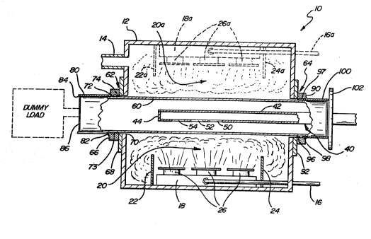
lo F;gure 1, illustrates, in cross-section
microwave energy apparatus 10 for sustaining a
substantially uniform microwave plasma over a
relatively large area. As used herein, the term
"large area" refers to a body having at least one
dimension greater than one microwave wavelength, and
preferably greater then twelve inches. The apparatus
10 includes, inter alia, a vacuum vessel 12, the walls
of which are preferably formed of a durable, corrosion
resistant material such as stainless steel. The
20 vacuum vessel 12 further includes a pump-out port 14
adapted for suitable connection to a vacuum pump for
i` maintaining the interior of the vacuum vessel 12 at an
appropriate sub-atmospheric pressure. The vacuum pump
is further adapted to remove reaction products from
the interior of said vessel 12.
he vessel 12 further includes at least one
process gas input line 16 connected to a process gas
input manifold 18, which manifold~l8 is operativeiy
disposed so dS to uniformly distribute process gases
30 ~ ~into the interior of said reaction vessel 12, and
specifically into the pl~asma-r~egion 20 thereof. The ~-
process gas input manifold 18 is operatively disposed
between at least a pair~ of process gas containment
means 22 and 24. The process gas containment means
~ 22, 24 contain the process gas introduced by the
:: ~; : :
~,
. . .
.
:: ; - , -.
. .
: ~ , '
:; .
1535
13176~
manifold 18 into the plasma region 20 of the vacuum
vessel 12. Also present within the plasma region 20
are means for supporting one or more substrates 26.
Though not shown, the vacuum vessel 12 may further
include means for maintaining the substrate at a
desired temperature, e.g., heating means or cooling
means.
As will be discussed in detail hereinbelow,
the substrate may include, but is not limited to, a
single elongated member, a plurality of small
substrates or a continuous web of substrate material.
It is to be specifically noted however, that while the
plasma region 20 is disposed at the bottom of the
vacuum vessel 12, due to the highly uniform nature of
the plasma sustained by the microwave energy apparatus
10, the plasma region 20 may in fact be located on the
top, bottom or sides of the vacuum vessel 12. Indeed,
as illustrated in Figure 1 in phantom, the plasma
region 20a may be located anywhere within the vessel
12. The substrate may be located at any distance from
0 the microwave plasma source, though in a preferred
embodiment, it is located a distance from said plasma
; source which does not exceed the near field distance
` of the microwave plasma source. This allows for
relatively high gas utilization rates.
The microwave energy apparatus 10 further
includes a microwave applicator 40 which extends at
least partially into the interior~of said vacuum
vessel 12. The microwave applicator 40 is adapted ~o
radiate microwave energy from~a source thereof, into
~the interior of said vacuum vessel 12 for initiating
and maintaining a p;lasma of the process gases
introduced into said vessel 12~by process gas manifold
18. As is illustrated in Figure 1, the microwaYe
applicator 40 comprises a substantially rectangular
waveguide 42 having an open end portion 44 at the
~ ~ .
: ~: : : :
: :: :
~;,:~ :
. ' ~
` 1535
13~7644
-14-
terminal end portion thereof extended into the vessel
12. The open end portion is adapted to avoid standing
waves. It is to be understood that the applicator
means 40 may alternatively be sealed at the terminal
end thereof. The waveguide means 42 includes a
plurality of apertures formed through one face
thereof. The apertures are dimensioned and spaced to
provide for the uniform radiation of microwave energy
therefrom.
Illustrated in greater detail in Figure 2, is
lo a partial perspective view of the microwave applicator
40, including the rectangular waveguide 42 having the
terrninal end portion 44, and a plurality of spacedly
disposed apertures, 46, 48, 50, 52 and 54 formed
through one face thereof. As is illustrated therein,
:: ,
apertures 46 and 48 are blocked by microwave absorbing
material to prevent microwave energy from radiating
therefrom. It is to be understood that the density of
the microwave energy radiated by the microwave
applicator 40 can be distributed in a desired,
controllable manner simply by blocking and partially
unblocking various ones of the apertures.
The inventors of the instant invention have
found that the size of the apertures is of great
signif~cance, in that the leak rate through any one of
said apertures is strongly dependent upon the size of
that aperture. While the size of the aperture may be
either larger or smaller tha~n a wavelength of
microwave energy9 in the embodiment o~ Figure 2, it is
preferred that the;aperture be~the size of, or smaller
~than one wavelength~of;microwave energy.
Additionally, the in~ventors h~ave found that by
partially unblocking~the apertures, the apparatus 10
is~capable of sustaining a plasma which is
substantially unif;orm.
Referring now to Figure 3, the embodiment of
~ ~ .
,~ .
. ~
1535
13176~
the microwave applicator 140 may include a microwave
waveguide 142 having an open end portion 144 thereof
and a single elongated, rectangular aperture 146,
larger than a wavelength of microwave energy, formed
through substantially the entire length and width
dimension of one face thereof. The open end portion
is adapted to avoid standing wave problems, though a
sealed end portion may be employed for a given
application. The applicator 140 allows microwave
energy to radiate from the entire aperture 146, though
lo without more, the concentration of microwave energy is
greatest at the end of the aperture nearest the source
of microwave energy. The concentration of the
` microwave energy, and consequently the of the density
of the plasma may be regulated by employing at least
one elongated either straight or slightly curved
metallic microwave shutter 150 operatively affixed to
said microwave waveguide 142 by a single connection
152 consisting of, for example, a pin 153 through a
channel 155, on the side of said waveguide nearest to
`~ 20 the source of microwave energy. Disposed at the
opposite end of said elongated aperture 146, and along
~; the edges of said aperture, are dielectric insulator
blocks 154 fabricated from, for example glass or
teflon. The dielectric insulator blocks 154 are
adapted to form an insulating barrier between the
waveguide 142 and the microwave shutter 150~ This is
necessary since the microwave shutter 150 may be
grounded to the waveguide means~l42 only at the
connection 152. Additional contact between the
~shutter 150 and the wavegui~de l42 will cause a so
called "~sizzling" ground, i.e., an arcing contact.
The applicator embodiments shown and
discussed in det~ail in connection with Figures 2 and 3
are of the type generally known as "leaky" microwave
structures in that microwave energy is allowed to leak
:: :
:
,: .. . ,,: : , , ,
: ~
1535
131 7~
-16-
or radiate therefrom through a plurality of
apertures. Alternatively, though not illustrated
herein, the microwave applicators may be slow wave
microwave structures. The slow wave structure
delivers a significant part of microwave energy by
means of evanescent waves. This type of slow wave
structure was discussed hereinabove with reference to
the Weissfloch, et al and Kieser, et al patents. The
microwave energy apparatus 10 of the instant invention
substantially obviates the shortcomings inherent in
lo slow wave structures, i.e., the rapid decline in
applied energy coupled to the plasma as a function of
distance along the direction transverse to the
microwave structure. This shortcoming is
substantially obviated herein by, inter alia,
isolating the microwave applicator from the plasma
region, thereby allowing the applicator to sustain a
more uniform plasma.
Returning now to Figure 1, the apparatus 10
further comprises means 60 for isolating the microwave
20 applicator 40 from the plasma region 20 within the
vacuum vessel 12. The isolating means 60 is
preferably fabricated from a dielectric material which
is substantially transparent to microwave energy. A
preferred material from which said isolating means 60
may be fabricated is quartz, though it is to be
understood that many other materials may be employed
with equal success. The isolating means 60 should
~urther be configured in a shape designed to optimize
its ability to withstand forces due to the presence of
30 a pressure differential. In this manner/ the
thickness of the isolatin;g means may be minimized to
provide for effective thermal cooling whereby high
; microwave power densities may be employed without
~; deleteriously effecting the isolating means. To this
end, a preferred shape for said isolating means is
' :
: .
.
:
13176~
cylindrical or hemi-cylindrical as to encapsulate at
least that portion of the applicator 40 which extends
into the vacuum vessel 12.
A cylindrical or hemi-cylindrical shape is
preferred to for example a planar shape, because a
thin cylinder is capable of withstanding pressures
(without collapsing) which would require a much
thicker planar plate. Thus, a planar plate to
thermally degrade, in a microwave plasma apparatus;
~;~ while a thin cylindrical isolating means 60 may be
lo uniformly cooled, without thermal degradation, and
therefore does not impose practical limitations upon
~ the amount of power which may be applied.
- Additionally, the applicator 40 should be
operatively disposed within the isolation means 60 and
~` spaced from the circumFerential wall thereof. When so
disposed, the applicator 40 may extend partially
` through the vacuum vessel 12, without being directly
exposed to the plasma region 20 contained therein.
The cylindrical isolating means 60 of Figure
i 20 1 is configured so as to be coextensive with at least
~` one dimension of the vacuum vessel 12, and protrude
through at least a first and second wall portion of
said vacuum vessel 12. The cylindrical isolating
means 60 is fixed through the walls of the vacuum
vessel 12 by means of two collar fittings 62 and 64
which are preferably fabricated from a suitable
non-corrosive material such ~as stainless steel. The
collar fittings 62 and 64 are preferably mountably
joined to the stainless steel vessel 12. Collar
fitting 62 comprises an open end portion 66 extending
from a connection~flange 68 affixed directly to a side
; wall of the vacuum vessel 12, and includes an opening
70 co-extensive with the circumference of the
cylln~drical isolating~means 60 and adapted to receive
cylindrical isolating means 60. Open end portion 66
~ ~ ,
: ~ :
.
1535
13176~
-18-
extends from said connection flange 68, and is adapted
to receive at least two 0-rings 72, 74, which 0-rings
72, 74 are adapted to effect a vacuum and water
barrier between the interior of said vacuum vessel 12
and outside ambient conditions. Between 0-rings 72,
74 is disposed a cooling channel 73 through which a
cooling medium such as water may be circulated to
maintain the 0-rings at a uniformly low temperature.
The 0-rings 72, 74 are preferably adapted to maintain
the vacuum and water seal at substantially elevated
o temperatures, i.e., temperatures in excess of 100
Centigrade.
The cylindrical isolating means 60 passes
through opening 70, connection flange 68, and the open
end portion 66. In this way, 0-rings 72, 74 are urged
against the outside circumference of said cylindrical
isolating means 60. The compression of the O~rings
72, 74 against the cylindrical isolating means 60
results in an air tight, water tight seal. It is
important to note that the location of 0-rings 72, 74
20 is well outside the plasma region 20 of the apparatus
10. This is noteworthy because by keeping the 0-rings
out of the plasma region 20, they are not exposed to
the excessive temperatures associated with microwave
plasmas, i.e., temperatures in excess of 500
~ centigrade. Had the 0-ring`seals been located within
`~ ~ the plasma region, as shown in the aforementioned U.S.
Patent No. 4,729,341, special (and costly) high
temperature resistant seals wou~ld have been required,
greatly increasing~the complex1ty and cost of the
30 ~ ~apparatus 10.
The cylindrical isolating means 60 may extend
beyond~the outside terminal edge of said open end
;portion 66. This~ portion of the cylindrical isolating
means 60 must thus be equipped with microwave
containment means ~80. ~The microwave containment means
,
:~` ~ : ,
`' ,, :'.
.
` 1535
1317~4
, g
-
80 is typically fabricated from a metal microwave
containment canister operatively affixed around the
outside circumference of the cylindrical isolating
means 60, and in electrical contact with said open end
portion 66 by grounding fingers 82. The microwave
containment canister is fabricated so as to be
coextensive with that portion of cylindrical isolating
means-60 which extends beyond the open end portion
66. Additionally, the microwave containment means 80
further includes an open end portion 84 over which is
lo disposed a metallic microwave blocking mesh 86 adapted
to contain stray microwaves therewithin. The mesh 86
is also adapted to allow for the passage of a flux of
~ cooling air through the cylindrical isolating means
; 60. Alternatively, and as is illustrated in phantom
in Figure 1, the open end portion 84 of the microwave
containment canister 80 may be attached to a dummy
load adapted to absorb excess microwave radiation.
This embodiment is particularly useful at high power
levels, where excess reflected microwave energy causes
20 reflection modes which may degrade the uniformity of
the microwave plasma.
The vacuum vessel 12 is further adapted to
receive the cylindrical isolating means 60 through at
; least a second wall portion thereof, preferably the
wall portion opposite the wall portion upon which
collar fitting 62 is mounted. Collar fitting 64 is
disposed on said opposlte wall~position, substantially
in line with collar fitting 62.` Collar fitting 64
comprises an open en~d portion 90 extended from a
;30 c`onnection flange 92. ~Connection flange 92 is affixed
directly to the opposite wall position and includes an
opening 94 co-extens~ive wi~th t~he circumference of the
cylindrical isolating means 68, and adapted to receive
the isolating means 60. The open end portion 90
extends from the conn~ection flange 92, and is adapted
:~ ~
.
1535
13~764~
-20-
to receive at least two 0-rings 96, 98 which are
adapted to effect a vacuum and water barrier between
the plasma region 20 within the vacuum vessel 12 and
the surrounding ambient conditions. Between 0-rings
96, 98 is disposed a cooling channel 97, through which
a cooling medium such as water may be circulated so as
to maintain the 0-rings at a uniformly low
temperature. The 0-rings 96, 98 like 0-rings 72, 74
are adapted to withstand elevated temperatures. The
cylindrical isolating means 60 is passed through
lo opening 94, through connection flange 92 and open end
portion 90 whereby 0-rings 96, 98 are urged against
the outside circumferential edge of said cylindrical
isolating means 60. The compression of said 0-rings
is the mechanism by which an air tight, water tight
~ seal is effected. Also, 0-rings 96, 98, like 0-rings
; 72, 74, are well out of the plasma region 20, and
therefore not subjected to degradation thereby.
By effecting an air-tight, water tight seal
around the outer circumference of the cylindrical
20 isolating means 60, lt is possible to maintain the
plasma region 20 at substantially sub-atmospheric
pressures, while the interior of the cylindrically
; isolating means 60 is maintained at atmospheric
pressures, and is directly exposed to ambient
conditions. This is in fact an advantage in the
operation of the apparatus lO. By maintaining the
vacuum vessel at sub-~atmospheric pressures, it is
possible to operat~e the apparatus lO at a pressure
approximating that~required for operation near the
3 0 ~ minimum~of a modified Paschen;curve. Additionally,
the low pressures~al~low~for a l;onger mean free path of
travel for the p~lasma~sp~eci~es;, t~hereby contributing to
overall plasma uniformity.~Sin~ce the interior of the
cyl~indrical isolating means 60 is exposed to ambient
condi~tions, a flux of~cooling~air may be maintained
:
:. , . : . , '
: .
~ 1535 131764~
-21-
-
therethrough so as to prevent the excessive heating
which may be associated with microwave plasmas.
Alternatively, a microwave transmissive cooling medium
such as silicon oil may be circulated within the
cylinder to maintain a uniform, cool temperature. The
cylindrical isolating means 60, extending beyond the
open end portion 90 must be sheathed within a metallic
microwave containment means 100, of the type described
~ hereinabove. The microwave containment means 100 is
;~ disposed adjacent to connection plate 102 which
lo affects a connection between the microwave applicator
means 40, and a source of microwave energy.
As described hereinabove, and as is
illustrated in Figure 1, the apparatus 10 defines a
plasma region 20 into which is disposed a substrate
28, at a distance not in excess of the distance
defined by the near field distance of the microwave
applicator 40. In a first embodiment, and as is
illustrated in Figure 4 where like reference number
refer to like structures, the substrate 28 disposed
20 into said plasma region 20 may take the form of a
; single, elongated planar or slightly curved substrate
member. Said planar substrate member 28 is
operatively disposed between the process gas
containment means 22, 24 and within the near field
distance of the applicator 40.
In an-other embodiment illustrated in Figure
5, the substrate member 28 may take the form of an
elongated, substantially continuous roll of substrate
material 30. In the case of a continuous roll of
s~ubstrate the appardt~us lO is mod;fied so as to allow
the continuous progres~s of substrate material
therethrough. Required modifications would include
gate means 32 adapted to allow the free passage of the
substrate member into and out of the vacuum vessel 12,
while maintaining the vàcuum and containing both the
~ : .
~ , :
: ` ~ ' ' .
: . ' . .
:- .
l535
13176~
-22-
;
process gases and -the microwave plasma. A preferred
gate means 32 for containing the reaction gases and
microwave plasma wi-thin the vacuum vessel 12 is
disclosed in U.S. Patent No. 4,438,723 -to Cannella, et
al~ In yet another embodiment, and as is
illustrated in Figure 6, the substrate comprises a
plurality of individual work pieces 34 supported in
the plasma region 20 by substrate support means 26,
and operatively disposed so as to have a plasma
operation performed upon the upper surfaces thereof.
As was discussed hereinabove, while each
embodiment is illustrated with the substrate members
28 disposed below the applicator 40, due to the
substantially uniform nature of the plasma, the plasma
region may be located anywhere within the near field
distance of the applicator 40. The input gas manifold
18 may provide into the plasma region 20 a process
material as metallic ma-terial, semiconductor material,
and dielectric material upon the substrate. In yet
another embodiment, the precursor gases introduced
into the plasma region decompose and deposit a clear,
hard film onto the substrate. In another embodiment,
at least one etchant precursor gas may be introduced
into the plasma region 20, whereby the apparatus 10 is
adapted to etch the surface of a substrate means
located therewithin. An example of a deposition
follows hereinafterO
EXAMPL~E
The microwave deposition apparatus 10
~ 30~ clescribed hereinabove was~employed to fabricate a
1~ ~ hard, clear silicon based coating upon a plurality of
individual glass subst~rates.~ The exact steps by which
the above described apparatus 10 is used to fabricated
,
;~
, , . , ' , ' . . .: , '
.
. . - . - ' : ' :, ' :
1535 ~176~
.
-23-
such coatings and deposits will be detailed
hereinbelow.
A plurality of substrate means fabricated of
glass were cleaned by common cleaning agents well
known to those skilled in the art. The glass
substrates were loaded in the plasma region 20 of
apparatus 10 described hereinabove. After placing the
glass substrates within the plasma region 20, the
apparatus 10 was closed and sealed so as to effect an
air tight seal between the interior of the vessel and
lo the surrounding ambient conditions. The interior of
the vessel was then evacuated to a pressure of
approximately 20 to 25 millitorr. Thereafter, the
interior of said chamber was purged in an argon gas
environment for a period of approximately one-half
hour. After purging for approximately one-half hour,
the chamber was evacuated to a background pressure of
approximately 3 to 4 millitorr. Thereafter, preferred
feedstock gases were introduced to ~he interior of
said chamber through said input gas manifold 18
according to the following recipe:
Gas Flow Rate
SiH4 110 SCCM
SiF4 ` ~ 31 SCCM
N2 ~ 475 SCCM
2 ~ 875 SCCM
14 SCCM
After initiating the flow of these feedstock
gases into the interlor of;the vacuum vessel, a
microwave plasma was ini~tiated, and at a frequency of
;` 2.45 GHz at a power o~f approximately 5 kilowatts. The
microwave plasm
~ ~ ,
,. ~
,~
~ ,
~ 1535
13176~
-24-
as to maintain a uniform low temperature. Thereafter,
microwave plasma was extinguished, and the flow of
process gases to the vacuum vessel 12 was terminated.
After extinguishing the plasma and
terminating the flow of process gases to the vacuum
vessel 12, the interior of the reaction vessel was
purged with argon, and the reaction vessel was vented
to ambient conditions. Thereafter, the reaction
vessel was opened and the substrate was removed for
examination which revealed a uniform, clear hard
silicon based coating.
While the invention has been described in
connection with preferred embodiments and procedures,
it is to be understood that it is not intended to
limit the invention to the described embodiments and
procedures. On the contrary it is intended to cover
all alternatives, modifications and equivalence may be
included within the spirit and scope of the invention
as defined by the claims appended herein and after.
,
:'~' ~ :
~ ` .
'' ~ '~'~'' '` ' ` ` ` ,.
' . ` .