Note: Descriptions are shown in the official language in which they were submitted.
1317784
~ASER DOPPLER ANEMOMETER
Background of the Invention
The invention relates to a laser Doppler
anemometer with at least two laser beams, which are
generated by a laser light source and which pass in
co~mon to a region of a fluid flow containing
particles. Light scattered from the region is
measured wherein the frequency of the light is
shifted by the Doppler frequency as a result of fluid
flow speed.
Such laser Doppler anemometers have been known
for a relatively long time. They are employed for
the virtually reaction-free measurement of flow
speeds of fluids which contain particles. In the
region of the flow, the two beams of the laser light
source generate a virtual interference pattern,
through which the particles of the fluid pass. The
frequency of the scattered light produced thereby is
shifted by the Doppler frequency in relation to the
output frequency of the laser light source.
1 3 1 7784
Continuously radiating laser light sources
have customarily been employed for the construction
of laser Doppler anemometers (L~A). To the extent
that pulsed lasers, e.g., pulsed laser diades (cf US-
PS 4,036,557) have been employed, the pulse durationhas been selected so as to be substantially greater
than the "transit time", i.e., the time which a
particle requires in order to traverse the
measurement region.
Continuously radiating lasers which have a
high output power for the generation of a good
signal-to-noise ratio for the measur0ment signals are
relatively voluminous systems, so that a measurement
configuration which is costly and difficult to handle
is required. Continuously radiating laser diodes,
which have been used for laser anemometry (DE~OS
3,435,433), have a relatively weak output power, so
that the signal-to-noise ratio o~ the measurement
signals permits the use of the corresponding system,
without costly supplementary measures, only for
specific fields of application. The same applies, in
principle, to the hitherto proposed pulsed laser
diodes; in this case, the evaluation of their
measurement si~nals led to considerable problems.
Summary of the Invention
The object of the invention is to provide a
laser Doppler anemometer of the initially mentioned
type so that an improved signal-to-noise ratio for
the measurement si~nals is produced, so that further
fields of application is also opened up with compact
systems.
-2-
-
13177~4
In a laser Doppler anemometer of the initially
mentioned type, this object is achieved, according to
the invention, in that the laser beams consist of
high-frequency pulses, the frequency of the pulse
sequence of which is a multiple of the Doppler
frequency.
The difference from the known laser Doppler
anemometers consists in that laser beams pulsed with
a very high frequency are employed, in which the
pulses exhibit a frequency of the pulse sequence
which is a multiple of, preferably between five and
twenty times, the Doppler frequency, so that the
pulse duration is only a small fraction of the
"transit time" of the particles.
Some lasers, especially semiconductor lasers,
can indeed emit in high-frequ~ncy pulsed operation
significantly more photons per second than in
continuous operation or in operation with long
pulses. To the same extent, the signal-to-noise
ratio thus increases, according to the invention, in
comparison with the continuous operation hitherto
employed in the LDA technique or with operation with
long laser pulses.
Accordingly, the Doppler measurement signal
(virtual interference fringe pattern) is always
scanned only for a ~rief period during the duration
of the laser pulses. The Doppler frequency signal
can be reconstructed, without further ado, from the
amplitude values of the corresponding scattered light
pulses and their temporal spacing, which accordingly
represent instantaneous values of the Doppler
frequency signal.
13177~4
A simple method for the evaluation of the
high-frequency measurement signals consists in that
the received scattered :Light pulses are formed into a
continuous analog measurement signal in an
integrator. Thus, the method of evaluation
corrPsponds to the evaluation of measurement signals
which are produced in the case of continuously
radiating laser light sources.
In an alternativ~e method of evaluation, which
is more advantageous with respect to the measurement
signal intensity, the measurement signal is fed to an
evaluation device, which includes an amplitude
measuring device for the respective scattered light
pulses which arithmetically evaluates the measured
amplitudes. A device which is particularly suitable
for this purpose is an amplitude measuring device
which performs the amplitude measurement of the
scattered light pulse present at the input in
response to a synchronizing pulse. In this case, the
synchronizing pulse and the laser pulse are expedi
ently derived from a common high-frequency pulse
generator. In the case of the last-mentioned method
of evaluation, no intensity losses for the
measurement signal arise as on account of the time
averaging. Rather, the Doppler measurement signal is
determined arithmetically using the instantaneous
amplitude measurement values, and its frequency,
which gives information on the flow speed.
An exceptionally preferred application of the
idea according to the invention arises where laser
diodes are used. In a preferred embodiment, ths
laser light source is thus formed by a laser diode.
1 3 1 77S4
The laser light source can, of course, also be formed
by a plurality of laser diodes.
The high~fre~uency laser pulses exhibit an 8X-
tremely short pulse duration, so that the light
intensity is considerably increased. As a result of
the pulse modulation of the diode, the optical output
power can be increased by several factors, also on a
time-average basis.
If a plurality of laser light sources are
provided for a plurality of speed components and if
the plurality of light sources irradiate in each
instance phase-shifted pulses, in such a manner that
only one laser light source radiates at any point in
time, it is possible to measure simultaneously a
plurality of speed components of the flow without
mutual interaction. In these circumstances, the two
or three laser light sourcas provided for two or
three speed components irradiate in each instance a
pulse within the pulse interruptions of the other
laser light source(s). The evaluation device
recognizes the amplitudes of the individual pulses,
which belong to a respective speed component, and
forms from these the Doppler signal associated with
each speed component. Since the emission of the
laser light pulses takes place within the pulse
interruptions of the other laser light sources for
the other speed components, a freedom from reaction
between the signals of the various speed components
is guaranteed.
This method makes it possible to receive all
signals of the various speed components using a
single receiving optical system, and to sort them
electronically for each component.
1 31 7784
Brief Description of the Drawi~s
The invention is to be explained in greater
detail hereinbelow wit:h reference to illustrative
embodiments represented in the drawings. In the
drawings:
Figure 1 shows a diagram of the const~uction
of a laser Doppler anemometer having a laser diode as
a laser light source and an evaluation device
including an integrator;
lo Figure 2 shows a similar diagram to that shown
in Figure 1 with an amplitude measuring device for
the brief scattered light pulses;
Figure 3 shows a diagram of the construction
of a laser Doppler anemometer according to Figure 2
having a plurality of laser light sources for a
plurality of speed components; and
Figure 4 shows a diagram according to Figure 3
with a different control of the various laser light
sources~
Detailed Description of the Preferred Embodiment
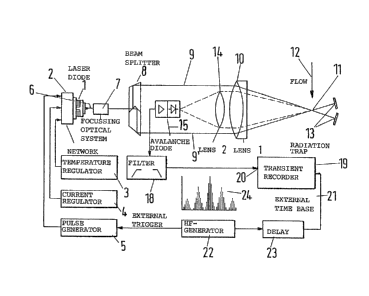
In the illustrative embodiment represented in
Figure 1, a laser diode 1 is driven by a network 2.
In order to regulate the wavelength of the laser
diode 1, the network 2 is connected to a temperature
regulator 3 and a current regulator 4. The
wavelength of the beams emitted by the laser diode 1
is kept constant by the current stabilization and
temperatura stabilization. To the network 2 there is
further connected a pulse generator 5, which causes
the laser diode 1 o emit laser pulses having an
~6--
1 3 1 77~
extremely short pulse duration. The laser beam 6 ir-
radiated by the laser diode 1 is focused by a
focusing optical system 7 and subsequently split up,
in a beam splitter 8, into two partial beams 9, 9',
which run parallel to one another. A collector lens
10 (lens 1) combines the two partial beams 9, 9' in a
point spot 11 (volume of intersection), which is
situatsd within the flow 12 of the fluid provided
with particles. The partial beams 9, 9' which have
passed through the flow 12 are absorbed by a
radiation trap 13, in order not to disturb the
maasurement.
The light scattered, in the illustrative
embodiment represented, backwards from the flowing
particles is focused by a focusing lens 14 (lens 2),
which is disposed in the optical axis of the first
lens 10, in such a manner that it falls on a
photodetector such as an avalanche diode 15. The
electrical signal generated by the avalanche diode 15
passes onto an integrator 16, which forms the
measurement signal into a continuous analog LDA
signal 17.
The further evaluation takes place in the
conventional manner which is known for anemometry
using continuously radiating laser light sources.
The illustrative embodiment represented in
Figure 2 corresponds in all essential parts of the
measurement configuration to the above described
configuration, so that the same reference numerals
have been employed for the same parts. There are
differences only as a result of the evaluation device
connected to the output of the avalanche diode 15.
Output pulses of the avalanche diode 15 pass, via 2
1 3 1 7784
filter 18 serving to eliminate interference, to a
transient recorder 19, which essentially represents a
fast analog-digital converter, which measures and
digitalizes the analog amplitude of the measurement
signal present at one of its inputs 20 (signal
input), when a trigger pulse is present at an
external time base 2:L. This trigger pulse is
generated by a high-fret~ency generator 22 and passes
via a delay circuit 23 to the input of the external
time base 21.
The high-frequency generator 22 serves at the
same time as generator for trigger pulses for the
pulse generator 5, so that the generation of the
laser pulses by means of the pulse generator 5 and
the generation of the trigger pulses for the
transient recorder 19 take place synchronously from
the same pulse source, namely the high-frequency
generator 22. The delay circuit 23 connected between
the hiyh-frequency generator 22 and the transient
recorder 19 takes into account the time delay between
the emission of the laser pulse by the laser diode 1
and the formation of the measurement pulse at the
output of the avalanche diode 15, so that the trigger
pulse is formed at the external time base 21 of the
transient recorder 19 in correct phase with the
appearance of the measurement pulse at the signal
input 20 of the transient recorder 19. A few periods
of a Doppler measurement signal 24 are dia-
grammatically represented in Figure 2. Tha Doppler
measurement signal 24 is put together by the
sequential addition of a plurality (e.g., thirty) of
amplitudes of brief measurement pulses and becomes
recognizable. Thus, the Doppler measurement signal
1 3 1 778~
24 is scanned pointwise by the laser pulses and
determined. As shown in Figure 2, this determination
can take place graphically, but preferably by means
of a computer.
In the computer, the signal-to-noise ratio can
be further improved by a digital filtering of the
measured scattered light: pulses. The determination
of the Doppler frequency takes place either in the
time range by nullpoint determination or in the
frequency range by a Fourier transformation (FFT).
A frequency of the pulse sequence of 10 to 50
MHz with pulse durations of 40 ns to 5 ns is set, for
example, for a Doppler frequency of e.g., 2 MHz. The
ratio of Doppler frequency and pulse frequency is
dependent upon the nature of the signal evaluation
and upon the type of laser diode employed. In order
to optimize the signal-to-noise ratio, the
appropriate operating parametars must be experi-
mentally determined.
Figure 3 shows an arrangement which is
intended for three laser light sources. Besides a
first laser light source 1, a second laser light
source 1' is shown, while, for reasons associated
with the clarity of representation, a third laser
light source is not represented. Although not
illustrated, it is understood that the light fro~
beamsplitter 8' is directed to the measuring point of
flow 12 via lens 10 and the scattered light is
fo~ussed onto diode 15 via focussing lens 10. For
the three laser light sources 1, 1' three pulse
generators 5, 5', 5" are provided, which are con-
nected to the high-frequency generator 22 via a
frequency divider 25. The frequency divider divides
13177~4
by three and triggers the three pulse generators 5,
5', 5" cyclically. Accordingly, the three laser
light sources 1, 1~, irradiate high-frequency pulses
having a frequency which corresponds to one-third of
the fre~uency of the high-frequency generator 22.
The duration of the laser light pulses is, in this
case, chosen so as to be so small that the laser
light pulses of the three laser light sources 1, 1'
do not overlap.
A pulse sequence is diagrammatically
represented in Figure 3; in this case, the output
pulses of the first laser light source 1 are
designated by LDl, those of the second laser light
source 1' by LD2 and those of the third laser light
source by LD3, and are represented in each instance
by solid, dotted and dashed lines.
It is clear that the transient recorder 19
must be triggered with the frequency of the high-
frequency generator 22, i.e., with three times the
frequency of the pulse sequence frequency of the
laser light sources 1,1'.
Figure 4 shows another embodiment for two
laser light sources 1,1', in which the pulse
generator 5 generates pulses with the frequency of
the high-frequency generator 22. In this case also,
it is assumed that the pulse width is substantially
smaller than the pulse interruption. The second
laser light source 1' is excited to radiate, by means
of an adjustable delay circuit 26, at such a temporal
spacing in relation to the first laser light source 1
that the laser pulses of the two laser light sources
1,1' are emitted equidistantly, as is represented
diagrammatically in Figure 4. The output pulses of
--10--
1 3 1 77~4
the first laser light source are shown by solid lines
and designated by LD1, while the output pulses of the
second laser light source 1' are shown in dashed
lines and designated by LD2.
In this case, the transient recorder 19 is
triggered by the pulses, which are summated in an
addition circuit 27, of the pulse generator as well
as of the delay circuit 26, i.e., with twice the
frequency of the high-frequency generator 22.
In both of the embodiments represented in
Figures 3 and 4, the scattered light pulses are
received by the common photodiode 15 and evaluated.
The amplitude measured by the transient recorder 19
are correlated, by appropriate software, in
individual speed components and evaluated with
respect to the respective Doppler frequency.
-11--