Note: Descriptions are shown in the official language in which they were submitted.
TITLE
Extended Nip Press selt Guide And Method
BACKGROUND OF THE INVENTION
This invention relates to web pressing. More partic-
ularly, the invention relates to the pressing of a travel-
ing web, such as paper, freshly formed from an aqueous
slurry of fibers in a press which includes a non-rotating
press member, such as a shoe. Still more particularly,
this i.nvention relates to a press of the type known in the
papermaking industry as an extended-nip press wherein the
web of paper travels through an area of contact between a
moving surface, such as a rotating roll, and a felt and
. belt carried on the roll surface and pressed against it by
a pressurized shoe having a face with a contour matching
an arcuate portion of the roll surface.
While such extended-nip type presses are relatively
new i.n the papermaking industry, there have been numerous
installations and various types of configurations~ Common
to all extended nip presses is the use of one or more
looped, flexible belts which travel through the nip with
the paper web and one or more felts. One side of the belt
contacts the web or felt, and its other side is in sliding
contact with a stationary element, commonly referred to as
a shoe, which provides a surface area of contact.
Since all machinery is not perfectly aligned, and in
view of the inevitable deflection, however slight, across
- the span of a papermaking machine, and other small
variations in the tolerances, construction or operation of
I
~ 3 ~
the apparatus, the belt tends to migrate to one end of the
press or the other during operation. In the past, this
undesirable operating characteristic has been corrected by
various means, such as by using movable guide rolls within
the looped belt. Another manner of guiding the belt has
been to mount the edges of the belt over a rotatable disc
disposed on either end of the press which maintains the
edges of the belt in a desired position relative to the
extended nip during operation. Finallyl guide plates have
been utilized within the looped belt to maintain its
location relative to the nip.
However, each of these prior methods of maintaining
the belt in a desired position during operation of the
extended-nip press has serious deficiencies. For example,
guide rolls and guide plates disposed within the belt
require additional equipment and produce additional
friction, or drag, in the belt while performing their
function of maintaining belt guidanceO
The belt guide incorporating a rotating disc at
either side of the belt perhaps provides the most positive
belt guidance, bu~ also produces the most serious defi-
ciency because the discs, in order to operate effectively,
must be biased axially outwardly, such as with springs, so
the belt is under a tension in the cross machine direc-
tion. This stresses the belt and greatly increases its
rate of wear since the belt is flexed through the nip in
the direction toward the longitudinal axis extending
~. 3 ~
across the machine while it is simultaneously being biased
outwardly by the rotating discs.
SUMMARY O~ T~ INVEN~ION
The above mentioned deficiencies and shortcomings of
prior devices for guiding the belt in an extended nip press
are obviated by this invention. According to the
invention, an extended nip web press is provided with a
frame, a rotatable roll having a longitudinal axis of
rotation and a travelling pressing surface, with the roll
mounted to the frame. The extended nip web prass is also
provided with a looped felt and looped belt corunning with
a web through the extended nip in a path or travel, and a
shoe and shoe support means opposite the roll and located
within the looped belt for providing nipping force between
the belt and the roll sur~ace. Belt position sensing means
for sensing lateral deviation of belt travel through the
extended nip in either direction along the length of the
nip and perpendicular to its path of travel are provided
for providing signals responsive to such movement of the
belt. An actuator for receiving the signals is also
provided, the actuator including means connected to the
shoe support means structure for moving the shoe in a
skewing motion relative to the roll surface and altering
the path of belt travel and its position in the extended
nip in response to the signals.
Thus, the shoe over which the moving belt is sliding
while passing through the extended nip, is mounted for
skewing movement relative to the nip. This is accomplished
by mounting the shoe in a piston block which, in turn, is
mounted in a beam extending longitudinally in the cross
machine direction. This beam is, in turn, connected to a
framework which is movable by a motorized jacXscrew
attached at one end, or both ends, of the framework. The
skewing movement is facilitated by providing pivoted
support rods which support the beam on which the extended-
1 3 ~
nip press shoe piston block is mounted to the framework ofthe rotatable roll. These support rods have two pivots at
either end to permit the rods to pivot in both the machine
and cross machine directions.
A control apparatus monitors the location of the belt
edge and signals a motor driving a jackscrew to skew the
end of the beam on which the shoe is mounted in a direction
whereby the rotating belt is urged toward the center of the
press. Since the belt and extended-nip press shoe are
already integral parts of the press, no additional guides
or rolls are required to effect the guiding operation.
Also, since the belt must pass through the extended ...
_ 3a _
~ 3 :~ 7 ~
nip anyway, during the normal course of operation, the
eneLgy requirement for effecting the guidance of the belt
is virtually nil. All that is required is to slightly
shift the well-lubricated pivoted framework slightly with
the motorized jackscrew.
Accordingly, it is an object of this invention to
provide an apparatus for efficiently and effectively
guiding the belt in an extended-nip press without the use
of additional guide rolls or surfaces.
Still another object of this invention is to provide
an apparatus for guiding the belt in an extended-nip press
wherein the power requirements for such guidance are
minimized.
Another object of the invention is to provide an
apparatus for guiding the belt in an extended nip-press
which does not stress the belt in addition to the stress
it encounters during its passage through the nip.
These and other objects, features and advantages of
the invention will become readily apparent to those
skilled in the art when the accompanying drawings are
viewed in conjunction with the description of the pre-
ferred embodiment described below.
IN THE DRAWINGS
Figure 1 is an end elevational view of the extended-
nip press showing the manner in which the press shoe is
mounted for skewing movement relative to the surface of
the backing roll.
--4--
Figure 2 is a top view, in somewhat schematic form,
showing the shoe slcewed relative to the backing roll axis
of rotation.
DESCRIPTION OF THE PREFERRED EMBODIMENT
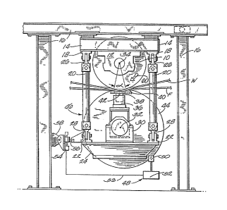
AS shown in figure 1, a backing roll 10 for an
extended- nip press is mounted with its bearing housing 12
on either end bolted to a short backing roll beam 14
which, in turn, is attached to its coreesponding side of
the papermaking machine press framework 16. The short
beams 14 extend in the so-called machine directionl which
is the direction the web of paper travels as it is formed
in the papermaking machine. Mounted to the short beam 14
at either end of backing roll 10 are a pair of clevises
18, one at either side of each end of the backing roll,
and a support rod 20 is pivotally attached to each clevis
and extends downwardly where its other end is pivotally
attached to a clevis 22 on either end of a correspondirlg
lower press beam 24 on each side of the press frame.
The clevises 18, 22 permit the rods to pivot in the
cross-machine direction which is at right angles to the
machine direction. The upper and lower ends of the
support rods are, in turn, pivotally mounted in corre-
sponding upper and lower couplings 26,28 in their clevises
for pivotal movement of the rod in the machine direction.
~ support beam 30 îs mounted on either end to the
lower press beam 24. The support beam 30 thus extends
longitudinally in the cross-machine direction with its
longitudinal axis 32 parallel with the longitudinal axis
~ 3 ~
of ~otation 34 of backing roll 10. A piston block 36 is
mounted on the support beam 30 and coextends with it in
the cross-machine direction. ~s is well-known in the
extended nip press art, such a piston block includes an
open cavity toward the press nip in which a piston 38 is
mounted for slidable reciprocal motion by the application
of pressurized fluid against its lower surface within the
cavityO The sides of the piston 38 are sealed for such
sliding motion such that little or no pressurized fluid
escapes beyond the sides of the reciprocatlng piston.
on top of the piston is mounted a stationary shoe 40.
The upper surface of shoe 40 is concavely contoured to
provide a surface which either coincides with the curva-
ture of the surface of backing roll 10, or has its surface
formed of a slightly larger radius to provide a slight gap
at its upstream and/or downstream edges to permit lubri-
cating fluid to enter between the belt and its surface, as
will be desceibed in more detail below.
The shoe 40, in its normal operating position,
coextends in the cross-machine direction with the axis of-
rotation 34 of the backing roll 10 and the longitudinal
axis of the support beam. In the preferred embodiment,
shoe 40 is pivotally mounted to the piston 38 by a small
cylindrical rod 42 whose longitudinal axis also coextends
with both the axis of rotation 34 of the backing roll and
the longitudinal axis 32 of the support beam 30.
Disposed over the top of the shoe 40, and about the
support beam 30, is a looped, flexible belt 44.
~ 3 ~ rJ ~ ~ ~
Typicallyt belt fi4 is formed of a woven mat covered with
an elastomeric compound, such as rubber. This belt 44,
support beam 30, support rods 20, piston block 36 and shoe
40 can be collectively referred to as ~he extended-nip
press loading apparatus 46. The belt 44 extends in the
cross-machine direction between the lower press beams 24
on either side of the press for substantially the length
of shoe 40. Somewhere about the circumference of the
looped belt 44 is mounted a belt edge position sensing
apparatus 48 which, for example, can comprise a palm guide
or paddle 50 mounted to a control apparatus 52 which
provides signals through wire 53 to actuate a motor 54 to
turn in one direction or the other according to the
position of the edge of the looped belt relative to a
predetermined, centered position in the press. The motor
5-~ is mounted to a vertical beam of press frame 16 and has
its driveshaft connected to a jackscrew 5S which has one
end connected to a bracket 58 which, in turn, îs attached
to frame 16. The other end is attached to the lower press
beam 24. The connection of lower press beam 24 to a
vertical beam of frame 16 through motor 54, jackscrew 56
and bracket 58 stabilizes the extended-nip loading
apparatus relative to backing roll 10.
In operation, the piston 38 is actuated by hydraulic
fluid by means, not shown, such as a pump, to forcefully
position the shoe 40 against the surface of the`backing
roll with the paper web W and felt F between the belt 44
and the backing roll surface. As the paper web, felt and
~ 3 ~
belt pass through the area of contact provided between the
concave contour of the shoe 40 and the backing roll
surface, water is expressed from the paper web into the
felt. The web is thus compacted and dried to a further
extent while passing through the extended nip which is
substantially defined by the arcuate surface subtended by
the angle c~ of the belt, felt and web between the shoe
over the backing roll 10. The direction of travel for the
belt, felt and paper web is in the direction corresponding
to the arrow 60 on the backing roll 10. The pressurized
force of contact of the belt, felt and web against the
surface of the backing roll by action of the pressurized
shoe provides the driving force for moving the belt in its
looped path of travel.
When, during operation, the belt 44 tends to migrate
in the longitudinal direction beyond a predetermined place
on either end of the extended-nip press (i.e. in the
cross-machine direction), such movement is sensed by the
palm 50 of the control apparatus 52 which signals the
motor 54 to rotate the jackscrew 56 in a direction whereby
the end of the shoe ~0 is moved in a skewing motion, under
the constraint of the pivoted support rods 20, in a
direction such that the traveling belt is urged by the
frictional forces of its contact with the shoe surface to
move inwardly toward the center of the papermaking
machine, which is to say, toward the center of the
extended-nip press.
--8--
~L 3 ~ $
This skewing movement is shown in exa~gerated form,
for purposes of illust~ation, as angle~ between the
longitudinal axis 3~ of backing roll 10 and the longi-
tudinal axis 41 of shoe 40 in igure 2. The skewing
motion is represented by the double-headed arrow 43. In
other words, with reference to figure 1, the skewing
motion is substantially in a horizontal plane which is
tangent to the backing roll 10 at a point where a plane
through its axis of rotation 34 and the longitudinal axis
32 of the support beam 30 passes through its surface.
However, due to the pivoting of the support rods 20 in
conjunction with the turning of the concave surface of the
shoe 40 over the surface of the backing roll, the actual
skewing motion may not be in a true horizontal plane.
Naturally, various modifications may ~e made in the
apparatus without departing from the spirit or scope of
the invention. For example, a motor 54, jackscrew 56 and
bracket 58 may be mounted to either end of the apparatus
to provide increased stability and operational control.
Also, some other arrangement besides the support rods and
pivoted clevises could be used to movably support the
extended-nip loading apparatus 46. Finally, the surface
of the roll could be skewed relative to the surface of the
shoe.